1
Type8202
ELEMENT
pH- or redox-meter
pH- oder Redox-Messgerät
pH- ou redox-mètre
Operating Instructions
Bedienungsanleitung
Manuel d‘utilisation
We reserve the right to make technical changes without notice.
Technische Änderungen vorbehalten.
Sous réserve de modifications techniques.
© 2008-2012 Bürkert SAS
Operating Instructions 1203/3_EU-ML_560329 _Original_FR
Type 8202 ELEMENT
Contents
1.
About this manual......................................................................................................................................................................5
1.1. Symbols used...........................................................................................................................................................................5
1.2. Validity of the manual...........................................................................................................................................................5
2.
Intended use.....................................................................................................................................................................................6
2.1. Restraints....................................................................................................................................................................................6
3.
Basic safety information.....................................................................................................................................................7
4.
General information.................................................................................................................................................................9
4.1. Contact.........................................................................................................................................................................................9
4.2. Warranty conditions...............................................................................................................................................................9
4.3. Informations on the internet.............................................................................................................................................9
5.
Description.....................................................................................................................................................................................10
5.1. Area of application..............................................................................................................................................................10
5.2. General description............................................................................................................................................................10
5.2.1. Design.........................................................................................................................................................10
5.2.2. pH or Redox probe..................................................................................................................................10
5.3. Description of the name plate......................................................................................................................................11
5.4. Available versions................................................................................................................................................................11
6.
Technical data..............................................................................................................................................................................12
6.1. Conditions of use.................................................................................................................................................................12
6.2. Conformity to standards and directives..................................................................................................................12
6.3. General technical data......................................................................................................................................................13
6.3.1. Mechanical data........................................................................................................................................13
6.3.2. General technical data............................................................................................................................15
6.3.3. Electrical data............................................................................................................................................16
6.3.4. Data of connectors and cables.............................................................................................................16
6.3.5. pH/Redox probe.......................................................................................................................................17
7.
Assembly............................................................................................................................................................................................18
7.1. Safety instructions..............................................................................................................................................................18
1
English
Type 8202 ELEMENT
7.2. Unscrewing the cover........................................................................................................................................................18
7.3. Mounting the cover.............................................................................................................................................................19
7.4. Mounting the display module........................................................................................................................................19
7.5. Removing the display module......................................................................................................................................20
7.6. Mounting the probe into the holder (without fluid)...........................................................................................20
7.7. Mounting the electronic module to the sensor holder (without fluid)....................................................21
8.
Installation and commissioning................................................................................................................................22
8.1. Safety instructions..............................................................................................................................................................22
8.2. Installation onto the pipe.................................................................................................................................................23
8.3. Electrical wiring.....................................................................................................................................................................25
8.3.1. Assembling the male or female connector (accessories: see chap. 11)....................................25
8.3.2. Equipotentiality of the installation.........................................................................................................26
8.3.3. Wiring a version with a single M12 fixed connector........................................................................27
8.3.4. Wiring a version with 2 M12 fixed connectors..................................................................................29
9.
Operating and functions..................................................................................................................................................32
9.1. Safety instructions..............................................................................................................................................................32
9.2. Functions..................................................................................................................................................................................32
9.3. Using the navigation key.................................................................................................................................................33
9.4. Using the dynamic functions.........................................................................................................................................34
9.5. Example for the input of a numerical value..........................................................................................................35
9.6. Example for browsing in a menu................................................................................................................................35
9.7. Description of the display...............................................................................................................................................36
9.7.1. Description of icons and LEDs.............................................................................................................36
9.7.2. When switching on the device..............................................................................................................37
9.8. Read level.................................................................................................................................................................................37
9.9. Accessing the Settings level.........................................................................................................................................38
9.10. Menu structure of the Settings level.........................................................................................................................39
9.11. Parameters Menu.................................................................................................................................................................42
9.11.1. Transferring data from one device to another....................................................................................42
9.11.2. Setting the date and time.......................................................................................................................43
9.11.3. Modifying the PARAM menu access code.........................................................................................43
2
9.11.4. Restoring the default parameters of the Read level and the outputs...........................................43
English
Type 8202 ELEMENT
9.11.5. Setting the data displayed in the READ level....................................................................................44
9.11.6. Displaying the lowest and highest values measured.......................................................................45
9.11.7. Setting the display contrast and brightness......................................................................................45
9.11.8. Choosing the output wiring mode........................................................................................................45
9.11.9. Setting the parameters of the current outputs..................................................................................46
9.11.10. Setting the parameters of the transistor outputs..........................................................................47
9.11.11. Setting the sensor parameters..........................................................................................................48
9.12. Calibration menu ................................................................................................................................................................49
9.12.1. Activating/deactivating the Hold function...........................................................................................49
9.12.2. Modifying the Calibration menu access code...................................................................................50
9.12.3. Adjusting the current outputs................................................................................................................50
9.12.4. Calibrating the sensor.............................................................................................................................51
9.12.5. Entering an offset for the temperature measurement......................................................................55
9.13. Diagnostic menu..................................................................................................................................................................55
9.13.1. Modifying the Diagnostic menu access code....................................................................................55
9.13.2. Monitoring the condition of the probe.................................................................................................55
9.13.3. Monitoring the fluid temperature...........................................................................................................56
9.14. Test menu ..............................................................................................................................................................................57
9.14.1. Modifying the Test menu access code................................................................................................57
9.14.2. Checking the outputs functions............................................................................................................57
9.14.3. Checking the outputs behaviour...........................................................................................................58
9.15. Information menu................................................................................................................................................................58
9.15.1. Reading the cause of events linked to icons.....................................................................................58
9.15.2. Reading the software versions..............................................................................................................59
10.
Maintenance and troubleshooting........................................................................................................................60
10.1. Safety instructions..............................................................................................................................................................60
10.2. Cleaning of the transmitter.............................................................................................................................................60
10.2.1. Cleaning of the pH/ORP probe............................................................................................................60
10.3. Replacing the probe...........................................................................................................................................................61
10.4. Replace the seal of the sensor holder.....................................................................................................................62
10.5. Troubleshooting....................................................................................................................................................................63
11.
Spare parts and accessories.......................................................................................................................................69
12.
Packaging, Transport...........................................................................................................................................................69
English
3
Type 8202 ELEMENT
13.
Storage...............................................................................................................................................................................................70
14.
Disposal of the product...................................................................................................................................................70
4
English
Type 8202 ELEMENT
About this manual
1.
About this manual
This manual describes the entire life cycle of the device. Please keep this manual in a safe place, accessible to all
users and any new owners.
This manual contains important safety information.
Failure to comply with these instructions can lead to hazardous situations.
• This manual must be read and understood.
1.1.
Symbols used
danger
Warns you against an imminent danger.
• Failure to observe this warning can result in death or in serious injury.
WARNING
Warns you against a potentially dangerous situation.
• Failure to observe this warning can result in serious injury or even death.
CAUTION
Warns you against a possible risk.
• Failure to observe this warning can result in substantial or minor injuries.
NOTE
Warns you against material damage.
• Failure to observe this warning may result in damage to the device or system.
Indicates additional information, advice or important recommendations.
Refers to information contained in this manual or in other documents.
→→Indicates a procedure to be carried out.
1.2.
Validity of the manual
The manual describes the devices from V2 software version of the acquisition / conversion module for the
measured process values.
Check this sofware version on the device in the menu Info -> Software -> Versions -> Main.
5
English
Type 8202 ELEMENT
Intended use
2.
Intended use
Use of this device that does not comply with the instructions could present risks to people, nearby
installations and the environment.
• The 8202 transmitter is intended solely for the measurement of:
-- the pH in clean liquids or liquids containing solids, sulphides or proteins.
-- or the oxidation reduction potential in clean liquids or liquids containing solids, sulphides or proteins which
may present low conductivity.
• This device must be protected against electromagnetic interference, ultraviolet rays and, when installed outdoors, the effects of climatic conditions.
• This device must be used in compliance with the characteristics and commissioning and use conditions
specified in the contractual documents and in the user manual.
• Requirements for the safe and proper operation of the device are proper transport, storage and installation, as
well as careful operation and maintenance.
• Only use the device as intended.
2.1.
Restraints
Observe any existing restraints when the device is exported.
6
English
Type 8202 ELEMENT
Basic safety information
3.
Basic safety information
This safety information does not take into account:
• any contingencies or occurrences that may arise during assembly, use and maintenance of the device.
• the local safety regulations that the operator must ensure the staff in charge of installation and maintenance
observe.
Danger due to high pressure in the installation.
• Stop the circulation of fluid, cut off the pressure and drain the pipe before loosening the process connections.
Danger due to electrical voltage.
• Shut down and isolate the electrical power source before carrying out work on the system.
• Observe all applicable accident protection and safety regulations for electrical equipment.
Danger due to high fluid temperatures.
• Use safety gloves to handle the device.
• Stop the circulation of fluid and drain the pipes before loosening the process connections.
Danger due to the nature of the fluid.
• Respect the regulations on accident prevention and safety relating to the use of aggressive fluids.
Various dangerous situations.
To avoid injury take care:
• to prevent any unintentional power supply switch-on.
• to carry out the installation and maintenance work by qualified and skilled staff with the appropriate tools.
• to guarantee a set or controlled restarting of the process after a power supply interruption.
• to use the device only if in perfect working order and in compliance with the instructions provided in the user
manual.
• to observe the general technical rules during the planning and use of the device.
• not to use this device in explosive atmospheres.
• not to use this device in an environment incompatible with the materials from which it is made.
• not to make any external modifications to the device. Do not paint or varnish any part of the device.
• not to use fluid that is incompatible with the materials of which the transmitter is made.
• not to subject the device to mechanical loads (e.g. by placing objects on top of it or by using it as a step).
NOTE
The device may be damaged by the fluid in contact with.
• Systematically check the chemical compatibility of the component materials of the transmitter and the fluids
likely to come into contact with it (for example: alcohols, strong or concentrated acids, aldehydes, alkaline
compounds, esters, aliphatic compounds, ketones, halogenated aromatics or hydrocarbons, oxidants and
chlorinated agents).
7
English
Type 8202 ELEMENT
Basic safety information
NOTE
Elements / Components sensitive to electrostatic discharges
• This device contains electronic components sensitive to electrostatic discharges. They may be damaged if
they are touched by an electrostatically charged person or object. In the worst case scenario, these components are instantly destroyed or go out of order as soon as they are activated.
• To minimise or even avoid all damage due to an electrostatic discharge, take all the precautions described in
the EN 61340-5-1 and 5-2 norms.
• Also ensure that you do not touch any of the live electrical components.
8
English
Type 8202 ELEMENT
General information
4.
General information
4.1.
Contact
To contact the manufacturer of the device use following address:
Bürkert SAS
Rue du Giessen
BP 21
F-67220 TRIEMBACH-AU-VAL
The addresses of our international branches can be found on the Internet at: www.burkert.com
4.2.
Warranty conditions
The condition governing the legal warranty is the conforming use of the 8202 in observance of the operating conditions specified in this manual.
4.3.
Informations on the internet
You can find the user manuals and technical data sheets regarding the type 8202 at: www.burkert.com
9
English
Type 8202 ELEMENT
Description
5.
Description
5.1.
Area of application
The 8202 transmitter is intended solely for the measurement of:
• the pH in clean liquids or liquids containing solids, sulphides or proteins.
• or the oxidation reduction potential in clean liquids or liquids containing solids, sulphides or proteins which may
present low conductivity.
Thanks to two fully adjustable transistor outputs, the transmitter can be used to switch a solenoid valve, activate
an alarm and, thanks to one or two 4-20-mA current outputs, establish one or two control loops.
5.2.
General description
5.2.1.
Design
The 8202 transmitter comprises:
• a module for measuring process values, comprising:
-- a pH or Redox sensor measuring a potential difference (PD) in mV
-- a Pt1000 temperature sensor built in the holder of the pH or Redox sensor, measuring a resistance.
• an acquisition / conversion module for the process values measured:
-- measured PD acquisition in mV
-- conversion of the measured PD into pH units (for a transmitter with pH sensor only)
-- acquisition of the resistance measured and conversion into temperature
• a display module with browse button used to read and/or configure the parameters of the device. The display
module is available as an accessory.
One version of the 8202 transmitter with two transistor outputs and a 4-20 mA output operates on a 2-wire
system and requires a power supply of 14-36 V DC. For such a version, electrical connection is done via an M12,
5-point, male fixed connector.
One version of the 8202 transmitter with two transistor outputs and two 4-20 mA outputs operates on a 3-wire
system and requires a power supply of 12-36 V DC. For such a version, electrical connection is done via an M12,
5-point, male fixed connector and an M12, 5-point, female fixed connector.
5.2.2.
pH or Redox probe
The transmitter 8202 can be fitted with a standard probe 120 mm long, measuring the pH or the oxidation
reduction potential.
It is screwed into a holder with the built-in Pt1000 temperature probe.
• The pH probe is a glass membrane with variable sensitivity according to the pH. When the pH probe is
immersed in a solution, a difference in potential is formed, due to the hydrogen ions (H+), between the glass
membrane and the solution. This difference in potential, measured in relation to a reference electrode, is directly
proportional to the pH value (59.16 mV per pH unit at 25°C).
10
• When a Redox probe is immersed in a solution, an exchange of electrons occurs based on the oxidizing and
reducing effects of an electrolyte. The resulting voltage is the oxidation reduction potential.
English
Type 8202 ELEMENT
Description
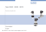
Description of the name plate
Made in France
5.3.
8202 pH/ORP Transmitter
Supply: 14-36VDC 40W Max
Output: 1x4-20mA 2xTrans 1A Max
Cell:pH -2/16 ORP +-2000mV 120mm PG13.5
Process: Temp 0/50°C limited by cell
PN 16 Bar limited by cell
11
IP65 -IP67
10
9
S-N:1110
W43LP
2:NPN/PNP1
3:0V
00559630
1
2
3
4
5
6
1:V+
7
4:NPN/PNP2
1. Type of transmitter and parameter measured
2. Electrical power supply and power consumption
3. Output specifications
4. Sensor specifications
5. Temperature range of the fluid, without sensor
6. Nominal pressure of the fluid, without sensor
8
7. Allocation of the pins on the M12 fixed
connectors
8. Construction code
9. Order code
10.Serial number
11.Protection rating
Fig. 1
Name plate on the 8202 transmitter
5.4.
Available versions
The following versions of the 8202 pH transmitter are available. These references include the electronic module
and the sensor holder including the Pt1000.
The pH/Redox sensor, the display module and the fitting for connection to the process should be ordered separately. For the pH/Redox sensor and the display module, see the list of accessories in Chapter 11
Electrical
connection
2 transistors + Male 5-pin M12
1 x 4-20 mA
fixed connector
Voltage supply Outputs
Sensor
14-36 V DC
without
Nut
material
PVC
PVDF
12-36 V DC
2 transistors + Male 5-pin M12
2 x 4-20 mA
fixed connector
+ female 5-pin
M12 fixed
connector
without
PVC
PVDF
UL
Order code
no
559630
yes
559634
no
559632
yes
559636
no
559631
yes
559635
no
559633
yes
559637
11
English
Type 8202 ELEMENT
Technical data
6.
Technical data
6.1.
Conditions of use
Ambient temperature
-10 to +60 °C (without pH or Redox probe)
Air humidity
< 85 %, non condensated
Protection rating
IP65 and IP67 with connectors plugged in and tightened and electronic
module cover fully screwed down
6.2.
Conformity to standards and directives
The device conforms to the CE directives through the following standards:
• EMC: EN 61000-6-2, EN 61000-6-3
• Vibration: EN 60068-2-6
• Shock: EN 60068-2-27
• Pressure: complying with article 3 of §3 from 97/23/CE directive. Acc. to the 97/23/CE pressure directive, the
device can only be used in the following cases (depending on max. pressure, pipe diameter and fluid):
Type of fluid
Fluid group 1, §1.3.a
Fluid group 2, § 1.3.a
Fluid group 1, § 1.3.b
Fluid group 2, § 1.3.b
Conditions
only DN25
DN ≤ 32
or DN > 32 and PNxDN ≤ 1000
DN ≤ 25
or DN > 25 and PNxDN ≤ 2000
DN ≤ 125
The UL devices conform to the following standards:
• UL 61010-1
• CAN/CSA-C22.2 n° 61010-1
12
English
Type 8202 ELEMENT
Technical data
6.3.
General technical data
6.3.1.
Mechanical data
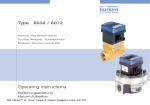
• A: application range of a 8202 with a PVDF nut
A
P (bar)
16
15
14
13
12
11
10
9
8
7
6
5
4
3
2
1
0
B
PVDF
PVC
PVDF
-20
0
+20
+40
+60
+80
+100
P (psi)
232
217.6
203
188.6
174
159.6
145
130.6
116
101.6
87
72.5
58
43.5
29
14
0
+120 +140
• B: application range of a 8202 with a PVC nut
The measures have been made at an ambient
temperature of 60 °C
P = Fluid pressure
T = Fluid temperature
T (°C)
Fig. 2
Fluid temperature / pressure dependency of the 8202 (without the probe) with a PVC or PVDF nut
P (bar) 16
15
Metal
14
13
12
11
10
9
8
7
PVC + PP
6
5
4
3
2
1
0
-20 0 +20 +40 +60
Fig. 3
P = Fluid pressure
T = Fluid temperature
Fluid temperature / pressure dependency of the 8202 (without the probe) with a PVC nut and a metal, PVC or PP
S022 adapter
P (bar) 16
15
14
13
12
11
10
9
8
7
6
5
4
3
2
1
0
Fig. 4
232 P (psi)
217.6
203
188.6
174
159.6
145
130.6
116
101.6
87
72.5
58
43.5
29
14
0
T (°C)
232 P (psi)
217.6
203
188.6
174
159.6
145
130.6
PVC + PP
116
101.6
87
72.5
58
PVC
43.5
29
PP
14
0
-20
0 +20 +40 +60 +80 +100 +120 +140 T (°C)
Metal
P = Fluid pressure
T = Fluid temperature
Fluid temperature / pressure dependency of the 8202 (without the probe) with a PVDF nut and a metal, PVC or
PP S022 adapter
13
English
Type 8202 ELEMENT
Technical data
Nickel-plated
brass
Stainless steel
PC
Part
Material
EPDM
Box / seals
stainless steel, PPS / EPDM
PPS
Cover / seal
PC / EPDM
Display module
PC / PBT
M12 fixed connector
nickel-plated brass
Fixed connector holder
stainless steel 1.4404 (316L)
Screws
stainless steel
Nut
PVC or PVDF
Sensor holder / seal (in
contact with the fluid)
pH or Redox probe
PVDF, stainless steel 1.4571
(316Ti) / EPDM
refer to the related manual
EPDM
PPS
EPDM
pH/Redox probe
PVDF
PVC or PVDF
PVDF
Stainless steel
316Ti
Materials used in the transmitter 8202 (without the probe)
260
175
210
Fig. 5
78
50
59
23.8
111
75
20
Fig. 6
Dimensions of transmitter 8202 [mm]
14
English
Type 8202 ELEMENT
Technical data
6.3.2.
General technical data
Pipe diameter
Type of fitting
DN25 to DN110 (DN15 to DN20 under specific
conditions)
Adapter S022
Nut between the 8202 and the fitting
Max. fluid temperature
G 1 1/2'' internal thread
The fluid temperature may be restricted by the probe
used (see the related instruction manual), by the
pressure of the fluid and the material of the adapter
S022
• with a PVDF nut (see also Fig. 2and Fig. 4)
• -20 to +130 °C
• with a PVC nut (see also Fig. 2 and Fig. 3)
Max. fluid pressure
• 0 to +50 °C
PN16
The fluid pressure may be restricted by the probe used
(see the related instruction manual), by the temperature
of the fluid and the material of the adapter S022 (see
Fig. 2, Fig. 3 and Fig. 4)
pH measurement
• Measurement range
• -2 to 16 pH or -580 to +580 mV
• Resolution
• 0.001 pH or 0.1 mV
• Accuracy
• ±0.02 pH or 0.5 mV
• Recommended min. divergence of the pH range
associated to the 4-20 mA signal
• 0.5 pH unit or 30 mV (eg: range 6,7 to 7,2 pH or
-20 mV to +10 mV associated to the 4-20 mA
output current)
Redox potential measurement
• Measurement range
• -2000 mV to +2000 mV
• Resolution
• 1 mV
• Accuracy
• ±3 mV
• Recommended min. divergence of the redox potential • 50 mV (eg: range 1550 to 1600 mV associated to
the 4-20 mA output current)
range associated to the 4-20 mA signal
Temperature measurement
• Measurement range
• -40 °C to +130 °C
• Resolution
• 0.1 °C
• Accuracy
• ±1 °C
• Recommended min. divergence of the temperature
range associated to the 4-20 mA signal
Temperature probe
• 10 °C (eg: range 10 to 20 °C associated to the
4-20 mA output current)
Pt1000 integrated in the sensor holder
Temperature compensation
• Automatic (integrated Pt1000)
• Reference temperature = 25°C
15
English
Type 8202 ELEMENT
Technical data
6.3.3.
Electrical data
Power supply
• Version with 3 outputs
• 14-36 V DC, filtered and regulated
• Version with 4 outputs
Characteristics of the power source (not supplied) of
the UL versions
• 12-36 V DC, filtered and regulated
• limited energy source (in accordance to UL 61010-1,
paragraph 9.3)
• or Class 2 source (in accordance to standards
1310/1585 and 60950-1)
Current consumption
• Version with 3 outputs
• 25 mA max. (at 14 V DC)
• Version with 4 outputs
Current consumption, with loads on the transistors
Power consumption
Protection against polarity reversal
Protection against voltage spikes
Protection against short circuits
Transistor output
• 5 mA max. (at 12 V DC)
1 A max.
40 W max.
yes
yes
yes, transistor outputs
Current output
NPN (/sink) or PNP (/source) (depending on software
setting), open collector, 700 mA max., 0.5 A max. per
transistor if both transistor outputs are wired.
NPN output: 0.2-36 V DC
PNP output: supply voltage
4-20 mA, sink ("NPN sink") or source ("PNP source")
(depending on software setting)
• Response time (10 % - 90 %)
• 150 ms (default value)
• Version with 1 current output
• max. loop impedance: 1100 W at 36 V DC, 610 W at
24 V DC, 180 W at 14 V DC
• Version with 2 current outputs
• max. loop impedance: 1100 W at 36 V DC, 610 W at
24 V DC, 100 W at 12 V DC
6.3.4.
Data of connectors and cables
Number of fixed connectors
1 male M12 fixed connector
Type of connectors
5-pin female M12 connector (not supplied).
For the M12 connector with order code 917116, use a shielded
cable:
• diameter: 3 to 6.5 mm
• wire cross section: max. 0.75 mm2
16
English
Type 8202 ELEMENT
Technical data
Number of fixed connectors
1 male M12 fixed connector and 1 female
M12 fixed connector
Type of connectors
5-pin female M12 connector (not supplied) and 5-pin male M12
connector (not supplied).
For the M12 connector with order code 917116, use a shielded
cable:
• diameter: 3 to 6.5 mm
• wire cross section: max. 0.75 mm2
6.3.5.
pH/Redox probe
The pH or redox probe must satisfies the following specifications:
• combined probe;
• length: 120 mm;
• with PG 13.5 head;
• with an S7/S8 fixed connector;
• without temperature probe.
The specifications of the probe can be found in the manual of the probe used.
17
English
Type 8202 ELEMENT
Assembly
7.
Assembly
7.1.
Safety instructions
warning
Risk of injury due to non-conforming assembly.
• The device must only be assembled by qualified and skilled staff with the appropriate tools.
Risk of injury due to unintentional switch on of power supply or uncontrolled restarting of the
installation.
• Avoid unintentional activation of the installation.
• Guarantee a set or controlled restarting of the process subsequent to any intervention on the device.
7.2.
Unscrewing the cover
note
The tightness of the transmitter is not guaranteed when the cover is removed.
• Prevent the projection of liquid inside the housing.
The transmitter may be damaged if a metal component comes into contact with the electronics.
• Prevent contact of the electronics with a metal component (screwdriver, for example).
→→To unscrew the cover, use your hand or a tool which can be used as a
lever, taking care not to scratch the glass.
→→Turn the cover until fully unscrewed.
Fig. 7
Unscrewing the cover
18
English
Type 8202 ELEMENT
Assembly
7.3.
Mounting the cover
→→Check that there is a seal on the cover and that it is not damaged. Replace
it if necessary.
→→Grease the seal if necessary, using a component compatible with the
seal material.
→→Fully tighten by hand to guarantee tightness.
Fig. 8
7.4.
Fitting the cover
Mounting the display module
→→Unscrew the cover (see chapter 7.2).
20°
→→Set the display module at an angle of ca. 20° in relation to the desired
position.
→→The module can be mounted in 4 different positions, at 90° intervals.
a)
c)
b)
d)
→→Fully push in the module and turn to the right to lock it.
Fig. 9
Mounting the display module
19
English
Type 8202 ELEMENT
Assembly
7.5.
Removing the display module
→→Unscrew the cover if necessary (see chapter 7.2).
→→Turn the module by ca. 20° to the left. Once unlocked, the module is raised
slightly by the spring action.
20°
→→Remove the module from its housing.
Fig. 10
Removing the display module
7.6.
Mounting the probe into the holder (without fluid)
probe head
H
compression washer
seal
Following instructions are valid for a Bürkert probe.
If you use a probe from another supplier, respect the related
instructions.
→→Remove the protective plugs
→→Check that dimension H on the probe is between 34 and 46mm. If necessary,
adjust the height of the compression washer.
→→At first use, apply water or soapy water on the "A" seal.
A
→→Insert the seal into the groove on the holder.
→→Insert the probe with its seal into the holder from above.
→→Tighten the probe head using a suitable wrench.
20
Fig. 11
Mounting the probe into the holder (without fluid)
English
Type 8202 ELEMENT
Assembly
7.7.
Mounting the electronic module to the sensor
holder (without fluid)
→→Check that the probe is mounted into the sensor holder (see chapter 7.6).
→→Check that seal "A" on the holder is in good condition. Replace it if
necessary (see Chap. 11)
→→Clean connectors "B" and "C" for connection of the pH/redox probe with
alcohol to avoid measurement errors.
→→Insert the electronic module into the holder, making sure the polarising
slots are correctly positioned.
→→Apply slight vertical pressure to engage the seal.
C
B
A
→→Fasten the electronic module and the holder together by tightening the
nut. Tighten the G 2'' nut by hand only, until it stops turning, to ensure
good electrical contact.
Fig. 12
Mounting the electronic module to the holder (without fluid)
→→Mount the display module (see chap. 7.4) to calibrate the transmitter.
→→Calibrate the transmitter (see chap. 9.12.4).
21
English
Type 8202 ELEMENT
Installation and commissioning
8.
Installation and commissioning
8.1.
Safety instructions
danger
Risk of injury due to high pressure in the installation.
• Stop the circulation of fluid, cut off the pressure and drain the pipe before loosening the process connections.
Risk of injury due to electrical voltage.
• Shut down and isolate the electrical power source before carrying out work on the system.
• Observe all applicable accident protection and safety regulations for electrical equipment.
Risk of injury due to high fluid temperatures.
• Use safety gloves to handle the device.
• Stop the circulation of fluid and drain the pipes before loosening the process connections.
Risk of injury due to the nature of the fluid.
• Respect the regulations on accident prevention and safety relating to the use of aggressive fluids.
warning
Risk of injury due to non-conforming installation.
• The electrical and fluid installation can only be carried out by qualified and skilled staff with the appropriate
tools.
• Install appropriate safety devices (correctly rated fuse and/or circuit-breaker).
• Respect the assembly instructions for the fitting used.
Risk of injury due to unintentional switch on of power supply or uncontrolled restarting of the
installation.
• Avoid unintentional activation of the installation.
• Guarantee a set or controlled restarting of the process subsequent to any intervention on the device.
warning
Danger due to nonconforming commissioning.
Nonconforming commissioning could lead to injuries and damage the device and its surroundings.
• Before commissioning, make sure that the staff in charge have read and fully understood the contents of the
manual.
• In particular, observe the safety recommendations and intended use.
• The device/installation must only be commissioned by suitably trained staff.
note
Risk of damage to the device due to the environment
• Protect this device against electromagnetic interference, ultraviolet rays and, when installed outdoors, the
effects of the climatic conditions.
22
English
Type 8202 ELEMENT
Installation and commissioning
8.2.
Installation onto the pipe
danger
Risk of injury due to high pressure in the installation.
• Stop the circulation of fluid, cut off the pressure and drain the pipe before loosening the process connections.
Risk of injury due to the nature of the fluid.
• Respect the regulations on accident prevention and safety relating to the use of aggressive fluids.
If a pH/redox probe (with PG 13.5 head, 120 mm long and without temperature probe) from a supplier
other than Bürkert is used, follow the relevant instructions on installation in the pipe.
→→Choose an appropriate position in the pipe to install
the fitting.
→→Fit the pipe with a fitting with G 1” ½ external
threaded sensor connection with respect to the
instructions delivered with the fitting.
Direction of the fluid
Fig. 13
Mounting positions in the pipe
75°
Fig. 14
75°
→→Fit the fitting at an angle of ±75° max. to the vertical
in order to ensure the good operation of the pH/redox
probe.
Angle to the vertical
The probe must always be immersed in the fluid to prevent it drying out.
→→Once the transmitter has been calibrated, remove the electronic module from the sensor holder as shown Fig.
15.
→→Unscrew the nut between the electronic module and the sensor
holder.
23
English
Type 8202 ELEMENT
Installation and commissioning
→→Remove the electronic module by pulling it straight out. There
may be a resistance due to the seal.
Fig. 15
Remove the electronic module from the sensor holder
→→Install the holder with its probe on the fitting as shown in Fig. 16.
→→Check the presence and the condition of seal B on the fitting.
Replace the seal if necessary.
→→Insert the holder with its probe carefully into the fitting.
B
→→Tighten the nut on the fitting by hand.
→→Charge the pipe to check the tightness of the assembly.
Fig. 16
Installing the sensor holder with its probe on a fitting
→→If the sensor holder is tight, insert the electronic module back onto the sensor holder as shown in Fig. 17.
→→Check that the electrical contacts are in good condition and
clean them with a brush if necessary.
electrical contacts
24
English
Type 8202 ELEMENT
Installation and commissioning
→→Check that seal "A" on the holder is in good condition.
Replace it if necessary (see chap. 11 and chap. 10.4).
→→Insert the electronic module into the holder, making sure the
polarising slots are correctly positioned.
polarising slots
A
→→Apply slight vertical pressure to engage the seal.
→→Fasten the electronic module and the holder together by
tightening the nut. Tighten the G 2'' nut by hand only, until
it stops turning, to ensure good electrical contact with the
temperature probe.
Fig. 17
Mounting the electronic module to the sensor holder, after installation of the holder on a fitting
8.3.
Electrical wiring
danger
Risk of injury due to electrical voltage.
• Shut down and isolate the electrical power source before carrying out work on the system.
• Observe all applicable accident protection and safety regulations for electrical equipment.
• Use a high quality electrical power supply (filtered and regulated).
• Make sure the installation is equipotential. See chap. 8.3.2.
8.3.1.
4
Assembling the male or female connector (accessories:
see chap. 11)
3
2
1
→→Unscrew the nut [1] on the body [4].
→→Insert the cable into the nut [1], the cable clamp [2] and the seal [3], and then into
the body [4].
25
English
Type 8202 ELEMENT
Installation and commissioning
→→Strip 20 mm of the cable.
5
,5
11
20
5,5
→→Cut the central wire (earth) so that its length is equal to 11.5 mm.
→→Expose 5.5 mm of the wires on the stripped cable.
→→Insert each wire into the appropriate pin on the terminal block [5] (see chap. 8.3.3
and 8.3.4).
→→Tighten the terminal block [5] wired to the body [4].
→→Tighten the connector nut [1].
Fig. 18
8.3.2.
M12 multi-pin connector (not provided)
Equipotentiality of the installation
To ensure the equipotentiality of the installation (power supply - device - medium):
→→Connect together the various earth spots in the installation to eliminate the potential differences that may
occur between different earthes.
→→Observe faultless grounding of the shield of the power supply cable.
→→Special attention has to be paid if the device is installed on plastic pipes because there is no direct earthing
Power supply
Fig. 19
12-36 V DC
possible. Proper earthing is performed by earthing together the metallic devices such as pumps or valves, that
are as close as possible to the device.
+
Equipotentiality skeleton diagram with pipes in metal
26
English
Type 8202 ELEMENT
Power supply
12-36 V DC
Installation and commissioning
Devices such as valves,
pumps,...
+
Pipes in plastic
Fig. 1
8.3.3.
Equipotentiality skeleton diagram with pipes in plastic
Wiring a version with a single M12 fixed connector
Transistor output 1
2
0V
1
3
V+ (14-36 V DC)
4
Transistor output 2
Fig. 20
Pin assignment of the fixed connector on a version with a single M12 fixed connector
Pin for the female M12 connector available as an accessory (order code
438680)
1
2
3
4
5
black
Load 2
(solenoid valve for instance)
3
brown
white
blue
black
grey
Load 1 (solenoid valve for instance)
white
2
Colour of the wire
brown
4
1
grey
blue
- +
Power supply
14-36 V DC
Fig. 21
NPN wiring of both transistor outputs (software setting "NPN/sink", see chap. 9.11.8), of a version with 1 M12
fixed connector
English
27
Type 8202 ELEMENT
Installation and commissioning
Load 1 (solenoid valve for instance)
white
2
black
3
brown
4
1
grey
blue
Load 2
(solenoid valve for instance)
- +
Power supply
14-36 V DC
Fig. 22
PNP wiring of both transistor outputs (software setting "PNP/source", see chap. 9.11.8), of a version with 1 M12
fixed connector
4-20mA input at external
device
4-20mA input at external
device
- +
2
3
- +
4
2
blue
brown
1
3
brown
4
1
grey
grey
blue
- +
Power supply
Power supply
14-36 V DC
Fig. 23
- +
14-36 V DC
Possible wirings of the current output (whatever the software setting, "NPN/sink" or "PNP/source", see
chap. 9.11.8), of a version with 1 M12 fixed connector
4-20mA input at external device
Load 1
- +
white
2
black
3
brown
4
1
grey
blue
- +
Load 2
Power supply
14-36 V DC
Fig. 24
NPN wiring of both transistor outputs and wiring the current output in sinking mode (software setting "NPN/sink",
see chap. 9.11.8), of a version with 1 M12 fixed connector
4-20mA input at external device
Load 1
white
2
black
Load 2
3
- +
blue
brown
4
1
grey
- +
Power supply
14-36 V DC
Fig. 25
28
PNP wiring of both transistor outputs and wiring the current output in sourcing mode (software setting " PNP/
source", see chap. 9.11.8), of a version with 1 M12 fixed connector
English
Type 8202 ELEMENT
Installation and commissioning
8.3.4.
Wiring a version with 2 M12 fixed connectors
0V
Transistor output 1
Transistor output 2
2
2
1
3
4
V+
1
(12-36 V DC)
V+
(12-36 V DC)
0V
4
Current output 2
Current output 1
Female fixed connector
Male fixed connector
Fig. 26
3
Pin assignment of the male and female M12 fixed connectors
Connect the power supply for the transmitter to the male fixed connector; the supply is then
transferred internally to pins 1 and 3 of the female fixed connector in order to ease wiring of the
load to the female fixed connector.
Pin of the M12 female cable available as an accessory (order code 438680)
1
2
3
4
5
Colour of the wire
brown
white
blue
black
grey
Pin of the M12 male cable available as an accessory (order code 559177)
1
2
3
4
5
Colour of the wire
brown
white
blue
black
grey
Load 1 (solenoid
valve for instance)
Load 2 (solenoid valve for
instance)
white
white
2
3
4
blue
2
brown
1
grey
- +
1
4
3
brown
Power supply
12-36 V DC
Fig. 27
NPN wiring of both transistor outputs of a version with 2 fixed connectors (software setting "NPN/sink", see
chap. 9.11.8)
29
English
Type 8202 ELEMENT
Installation and commissioning
Load 2 (solenoid valve for instance)
Load 1 (solenoid valve for
instance)
white
white
2
3
4
blue
2
brown
1
1
grey
- +
blue
3
4
Power supply
12-36 V DC
Fig. 28
PNP wiring of both transistor outputs of a version with 2 fixed connectors (software setting "PNP/source", see
chap. 9.11.8)
1st 4-20mA input at external device
2nd 4-20mA input at external
device
- +
- +
2
3
black
brown
4
1
2
brown
1
grey
black
blue
- +
4
3
Power supply
12-36 V DC
Fig. 29
Wiring of both current outputs in sinking mode, on a version with 2 fixed connectors (software setting "NPN/sink",
see chap. 9.11.8)
1st 4-20mA input at external device
2nd 4-20mA input at
external device
- +
- +
2
black
3
2
brown
4
1
grey
1
4
blue
3
black
blue
- +
Power supply
12-36 V DC
Fig. 30
Wiring of both current outputs in sourcing mode, on a version with 2 fixed connectors (software setting "PNP/
source", see chap. 9.11.8)
30
English
Type 8202 ELEMENT
Installation and commissioning
Load 1
Load 2
white
white
2
3
2
4
1
1
blue
brown
3
4
brown
grey
black
black
- +
- +
- +
12-36 V DC
1st 4-20mA input at external
device
2nd 4-20mA input at external
device
Power supply
Fig. 31
NPN wiring of both transistor outputs and wiring of both current outputs in sinking mode, on a version with 2 fixed
connectors (software setting "NPN/sink", see chap. 9.11.8)
Load 1
Load 2
white
white
2
3
blue
2
4
1
1
brown
4
3
blue
grey
black
black
- +
1st 4-20mA input at external
device
- +
12-36 V DC
- +
2nd 4-20mA input at external
device
Power supply
Fig. 32
PNP wiring of both transistor outputs and wiring of both current outputs in sourcing mode, on a version with 2
fixed connectors (software setting "PNP/source", see chap. 9.11.8)
31
English
Type 8202 ELEMENT
Operating and functions
9.
Operating and functions
9.1.
Safety instructions
warning
Risk of injury due to nonconforming adjustment.
Nonconforming adjustment could lead to injuries and damage the device and its surroundings.
• The operators in charge of adjustment must have read and understood the contents of this manual.
• In particular, observe the safety recommendations and intended use.
• The device/installation must only be adjusted by suitably trained staff.
9.2.
Functions
The device has 2 operating levels:
Read level
This level is used:
• to read the measured values of 2 process values selected in the Parameters menu,
• to read both the lowest and highest values of the chosen process value, that have been measured by the
device since the latest reset (this feature is not active by default),
• to reset both the lowest and highest values of the chosen process value, if the feature has been activated,
• to read the current values emitted on the 4-20 mA outputs.
Settings level
This level comprises 5 menus:
Menu title
"Param": see chap. 9.11
"Calib": see chap. 9.12
"Diagnostic": see chap. 9.13
"Test": see chap. 9.14
"Info": see chap. 9.15
32
English
Relevant icon
This is
when the
device is being parametered............
....................
Type 8202 ELEMENT
Operating and functions
9.3.
Using the navigation key
Symbolised by
this manual
in
Symbolised by
this manual
in
Symbolised by
this manual
Symbolised by
this manual
Symbolised by
this manual
Fig. 33
in
in
in
Using the navigation button
You want to...
...browse in Read level
Press...
• next screen:
• previous screen:
• ...display the Param menu
• ...access the Settings level
for at least 2 sec., from any screen of the Read
level
...browse in the menus of the Settings level
• next menu:
• previous menu:
...access the menu displayed
...browse in the menu functions
• next function:
• previous function:
...select the highlighted function
33
English
Type 8202 ELEMENT
Operating and functions
You want to...
...browse in the dynamic functions bar (MEAS, BACK,
ABORT, OK, YES, NO)
Press...
• next function:
• previous function:
...confirm the highlighted dynamic function
...modify a numerical value
-- increment the figure selected
--- decrement the figure selected
--- select the previous figure
-- select the next figure
-- allocate the "+" or "-" sign to the numerical value
--to the extreme left of the numerical value
--
until the desired sign is displayed
then
-- move the decimal point
-then
place
9.4.
to the extreme right of the numerical value
until the decimal point is in the desired
Using the dynamic functions
You want to...
...go back to the READ level, without validating the modifications made
...validate the input
...go back to the parent menu
... abort the current operation and go back to the parent menu
...answer the question asked
34
English
Choose...
dynamic function "MEAS"
dynamic function "OK"
dynamic function "BACK"
dynamic function "ABORT"
dynamic function "YES" or "NO"
Type 8202 ELEMENT
Operating and functions
9.5.
Example for the input of a numerical value
Modify each digit of the numerical
value using:
to increase the digit
selected,
Calib.Temp
Select the digit at
the extreme left of
the numerical value
to decrease the digit
selected.
+0.000°C
then with
allocate the "+"
or "-" sign to the
numerical value with MEAS ABORT OK
.
Dynamic functions (accessible through
9.6.
Select the digit at the extreme
right of the numerical value with
then move the decimal point
with
.
and
): see chap. 9.4
Example for browsing in a menu
Title of the current menu, sub-menu or
function.
The icon identifies the current
menu
This is
when the
device is being parametered............
....................
Highlighted
function
Param
Line1
Line2
Contrast
MEAS ABORT OK
Dynamic functions (accessible through
and
The arrow indicates that some more
functions are available which can be
displayed by using
The arrow indicates that some more
functions are available which can be
displayed by using ): see chap. 9.4
35
English
Type 8202 ELEMENT
Operating and functions
9.7.
Description of the display
9.7.1.
Description of icons and LEDs
LO
CK
EN
OP
Yellow LED: shows that
transistor 1 is switched
Green LED: shows that
the device is energized
Yellow LED: shows that
transistor 2 is switched
Red LED: shows an error;
see chap. 10.5
mV_pH
1423 mV
TempC
ERR
Red LED:
shows an error;
see chap. 10.5
not used
Yellow LED: shows that transistor 1 is switched
Fig. 34
23.8 °C
Yellow LED: shows that transistor 2
is switched
Position of the icons and description of the LEDs
The LEDs of the display module are duplicated on the electronic board that is located under the display
module: these LEDs become visible when the transmitter is not equipped with the display module.
Icon
Possible cause and alternatives
Probe in good condition and fluid temperature within the set range.
If the monitoring of the impedance on the electrodes and/or the fluid temperature has been activated, the alternative icons in this position are:
•
, associated with
: see chap. 9.13.2, 9.13.3, 9.15.1 and 10.5
• , associated with : see chap. 9.13.2, 9.13.3, 9.15.1 and 10.5
The device is measuring.
ERR
The alternative icons in this position are:
!
•
HOLD
flashing: HOLD mode activated (see chap. 9.12.1)
• T : running check that the outputs are working and behaving correctly (see chap. 9.14.2 and
9.14.3)
"maintenance" message; see chap. 9.12.4, 9.15.1 and 10.5
"warning" message; see chap. 9.11.10, 9.12.4 9.13.2, 9.13.3, 9.15.1 and 10.5
ERR
"error" message; see chap. 9.13.2, 9.13.3, 9.15.1 and 10.5
36
English
Type 8202 ELEMENT
Operating and functions
9.7.2.
When switching on the device
When the device is switched on or the display module mounted on the electronic module, the display indicates
the software version of the display.
The display then shows the first screen in READ level:
LO
CK
EN
OP
mV_pH
1423 mV
TempC
Fig. 35
9.8.
23.8 °C
Display indications when powering on the device
Read level
A
First view of the Read level.
mV_pH
1423 mV
TempC
1)
B
55 °C
Display of the current
outputs.
AC1
AC2
Zoom on the value in the
first line.
mV_pH
18.3 mA
7.5 mA
1)
1423mV
Zoom on the value of the
first current output.
AC1
18.3 mA
Zoom on the value in the
second line.
TempC
1)
55°C
Zoom on the value of the
second current output.
AC2
7.5 mA
Display of the highest and
lowest values of the physical quantity chosen
Max
Min
2)
1450mV
Reset Yes/No
1200mV
A
B
1)
To choose the process values to be displayed see chap. 9.11.5
The display of the lowest and highest values in the Read level is deactivated by default. To activate the feature and choose
the process values see chap. 9.11.3
2)
37
English
Type 8202 ELEMENT
Operating and functions
9.9.
Accessing the Settings level
This is
when the
device is being parametered............
....................
This is
when the
device is being parametered............
....................
Param
Parameters Menu
> 2s
Any display of the
Read level
This is
when the
device is being parametered............
....................
Code
"Param"
OK 1)
Wrong
code
Param
System
Display
Outputs
MEAS BACK
This is
when the
device is being parametered............
....................
Param
Display
Outputs
Sensor
MEAS BACK
Calib
Calibration
This is
when the
device is being parametered............
....................
Code
"Calib"
OK 1)
System
Outputs
Sensor
MEAS BACK
Calibration Menu
This is
when the
device is being parametered............
....................
Diagnostic
Code
"Diagnostic"
OK 1)
Diagnostic
System
Sensor
MEAS BACK
Diagnostic Menu
Test
Code
"Test"
OK 1)
Test
System
Outputs
Sensor
MEAS BACK
Test Menu
Info
Info
Error
Warning
Maintenance
MEAS BACK
Information Menu
Info
Maintenance
Smiley
Software
MEAS BACK
1)
Default code "0000"
→→See chap. 9.10 for the detailed menu functions
38
English
Type 8202 ELEMENT
Operating and functions
9.10. Menu structure of the Settings level
See chap. 9.9 to access the Settings level.
Param
System
This is
when the
device is being parametered............
....................
Up/Download
This is
when the
device is being parametered............
....................
Display
Download
Downl. Yes/No
Upload
Upload Yes/No
Date
YYYY/MM/DD
Time
HH:MMss
Code
0***
Factory reset
Reset Yes/No
Line1 / Line2:
Line1 / Line2:
Confirm code
If an “upload” has been done with this module
0***
Enabled
Disabled
This is
when the
device is being parametered............
....................
PVar:
pH
mV_pH
mV_ORP
TempF
TempC
Unit:
Filter:
pH
If PVar = "pH"
mV
If PVar = "mV_pH" or "mV_ORP"
°F
If PVar = "TempF"
°C
If PVar = "TempC"
None
Fast
Slow
Min/Max:
Status:
Enabled
Disabled
PVar:
pH
mV_pH
mV_ORP
TempF
TempC
Unit:
Contrast
xx%
Backlight
xx%
pH
If PVar = "pH"
mV
If PVar = "mV_pH" or "mV_ORP"
°F
If PVar = "TempF"
°C
If PVar = "TempC"
39
English
Type 8202 ELEMENT
Operating and functions
Param
Outputs
HWMode
This is
when the
device is being parametered............
....................
This is
when the
device is being parametered............
....................
sink/NPN
source/PNP
AC1/AC2
PVar:
On a version with 2 transistor outputs
pH
mV_pH
mV_ORP
TempF
TempC
4mA:
INPUT
20mA:
INPUT
Filter:
None
Fast
Slow
DiagnosMode:
None
22mA
TR1 / TR2
PVar:
pH
mV_pH
mV_ORP
TempF
TempC
warning
Mode:
Hysteresis
If PVar ≠ "warning"
Window
INPUT
If PVar ≠ "warning"
High:
INPUT
If PVar ≠ "warning"
Contact:
Normally open
Low:
Normal. closed
Delay:
Sensor
Type:
This is
when the
device is being parametered............
....................
INPUT
pH
ORP
Mode:
Symmetric
Asymmetric
Mains Fcy:
50Hz
60Hz
Calib
System
Hold
Hold:Disabled
Hold:Enabled
Outputs
40
English
Code
0***
Confirm code
AC1/AC2
4mA
INPUT
20mA
INPUT
0***
Type 8202 ELEMENT
Operating and functions
Calib
Sensor
Probe
Calib. Temp.
Auto
Constant
Calibration
1st point
NO
2nd point?
YES
If pH probe
Rinse
2nd point
Cal.Result
Probe constant
Calib. interval
Temperature
Diagnostic
Offset:
INPUT
Span:
INPUT
Last cal. date
VALUE
Interval
INPUT
0***
INPUT
System
Code
0***
Confirm code
Sensor
Glass electrode
Activate:
Yes/No
Impedance:
READ
Ref. electrode
Temperature
Warn high:
INPUT
Warn low:
INPUT
Err high:
INPUT
Err low:
INPUT
Activate:
Yes/No
Temperature:
READ
Warn high:
INPUT
Warn low:
INPUT
Err high:
INPUT
Err low:
INPUT
41
English
Type 8202 ELEMENT
Operating and functions
Test
System
Code
Outputs
AC1:
INPUT
AC2:
INPUT
TR1:
OFF/ON
TR2:
OFF/ON
PVar:
pH
Sensor
0***
Confirm code
0***
mV_pH
mV_ORP
TempF
TempC
Value:
Info
Error
MESSAGE
Warning
MESSAGE
Maintenance
MESSAGE
Smiley
MESSAGE
Software
Versions
INPUT
Main
READ
Sensor
READ
9.11. Parameters Menu
9.11.1. Transferring data from one device to another
See chap. 9.9 to access the Parameters menu.
The function is only possible with a display module with software version V2 and a transmitter with a V2
software version of the acquisition / conversion module for the measured process values.
• On the transmitter, check the sofware version of the acquisition / conversion module for the measured
process values in the menu Info -> Software -> Versions -> Main.
• The software version of the display module is displayed when the display module is energized.
• The “DOWNLOAD” function is only available if an UPLOAD has been successfully performed.
• Never interrupt an upload or download procedure else the transmitter may be damaged.
Param
System
This is
when the
device is being parametered............
....................
Up/Download
This is
when the
device is being parametered............
....................
42
English
Download
Downl. Yes/No
Upload
Upload Yes/No
Type 8202 ELEMENT
Operating and functions
The following data can be transferred from one device to another device of the same type:
• user settings in the menu PARAM (except the date, the time, the contrast level and the brightness of the
display),
• user settings in the menu DIAGNOSTIC,
• the access codes to the menus.
DOWNLOAD: transfer the data previously uploaded into the display module using the UPLOAD function.
The parameters transferred are used by the device as soon as the message “Download OK” is displayed.
UPLOAD: upload data from the transmitter to the display module.
9.11.2. Setting the date and time
See chap. 9.9 to access the Parameters menu.
Param
System
This is
when the
device is being parametered............
....................
This is
when the
device is being parametered............
....................
Date
YYYY/MM/DD
Time
HH:MMss
DATE: set the date (input format: year/month/day in the form YYYY/MM/DD)
TIME: set the time (input format: hours:minutesseconds)
9.11.3. Modifying the PARAM menu access code
See chap. 9.9 to access the Parameters menu.
Param
System
This is
when the
device is being parametered............
....................
Code
0***
Confirm code
Enter the new
code
This is
when the
device is being parametered............
....................
0***
Confirm the new
code
Default access code to the Parameters menu: 0000.
9.11.4. Restoring the default parameters of the Read level and the
outputs
See chap. 109 to access the Parameters menu.
Param
System
This is
when the
device is being parametered............
....................
Factory Set
This is
when the
device is being parametered............
....................
Execute
Reset Yes/No
Choose "Yes" to restore the default
parameters and "No" to keep the current
parameters.
43
English
Type 8202 ELEMENT
Operating and functions
9.11.5. Setting the data displayed in the READ level
See chap. 9.9 to access the Parameters menu.
Warning
Risk of injury due to wrong adjustment.
• Before setting the parameters for the display, choose the type of probe (see chap. 9.11.11) mounted on the
transmitter.
Param
Line1 / Line2:
Display
This is
when the
device is being parametered............
....................
Line1 / Line2:
Enabled
Disabled
This is
when the
device is being parametered............
....................
pH
PVar:
mV_pH
mV_ORP
TempF
TempC
Unit:
pH
If PVar = "pH"
mV
If PVar = "mV_pH" or "mV_ORP"
°F
If PVar = "TempF"
°C
If PVar = "TempC"
None
Filter:
Fast
Slow
PVAR: choose the process value to be displayed in the line selected. The possible choices depend on the
selected sensor type, whether pH or ORP.
UNIT: choose the unit for the process value displayed.
FILTER: choose the filter level for the measurement values displayed on the line selected. Three filter levels are
proposed: "slow", "fast" or "none". Fig. 36 shows the 3 filter curves.
30 s
"slow"
Fig. 36
Filter curves
44
English
t
6s
"fast"
t
150 ms
"none"
t
Type 8202 ELEMENT
Operating and functions
9.11.6. Displaying the lowest and highest values measured
See chap. 9.9 to access the Parameters menu.
Warning
Risk of injury due to wrong adjustment.
• Before setting the parameters for the display, choose the type of probe (see chap. 9.11.11) mounted on the
transmitter.
Param
Min/Max:
Display
This is
when the
device is being parametered............
....................
Status:
Enabled
Disabled
This is
when the
device is being parametered............
....................
PVar:
pH
mV_pH
mV_ORP
TempF
TempC
Unit:
pH
If PVar = "pH"
mV
If PVar = "mV_pH" or "mV_ORP"
°F
If PVar = "TempF"
°C
If PVar = "TempC"
STATUS: choose to display (choice “Enabled”) or not display (choice “Disabled”) the highest and lowest
measured values (of the process value chosen in PVAR hereafter) since the latest reset.
PVAR: choose the process value which highest and lowest measured values are displayed in the Read level.
UNIT: choose the preferred unit in which the lowest and highest measured values are displayed.
9.11.7. Setting the display contrast and brightness
See chap. 9.11.1 to access the Parameters menu.
On a version with one M12 fixed connector, do not increase the default setting of the display brightness
(parameter "Backlight").
Param
Display
This is
when the
device is being parametered............
....................
This is
when the
device is being parametered............
....................
Set each percentage using
Contrast
xx%
Backlight
xx%
and
.
CONTRAST: Choose the display contrast level (as a %).
BACKLIGHT: Choose the brightness of the display (as a %).
These settings only affect the display module. They are not factored in during a device data UPLOAD (see
chap. 9.11.1).
45
English
Type 8202 ELEMENT
Operating and functions
9.11.8. Choosing the output wiring mode
See chap. 9.9 to access the Parameters menu.
Param
HWMode
Outputs
This is
when the
device is being parametered............
....................
source/PNP
sink/NPN
This is
when the
device is being parametered............
....................
The setting has no effect on a version with one fixed connector, if the sole current output is wired. See
Fig. 23.
The wiring mode is the same for all outputs.
If you choose "sink NPN", the current outputs must be wired in sinking mode and the transistor outputs in NPN
mode.8.3
If you choose "source PNP", the current outputs must be wired in sourcing mode and the transistor outputs in
PNP mode.
See the wiring for the outputs in chap. 8.3.
9.11.9. Setting the parameters of the current outputs
See chap. 9.9 to access the Parameters menu.
Warning
Risk of injury due to wrong adjustment.
• Before setting the parameters for the outputs, choose the type of probe (see chap. 9.11.11) mounted on the
transmitter.
The 2nd current output "AC2" is only available on a version with 2 fixed connectors.
Param
Outputs
This is
when the
device is being parametered............
....................
AC1/AC2
PVar:
pH
mV_pH
This is
when the
device is being parametered............
....................
mV_ORP
TempF
TempC
4mA:
INPUT
20mA:
INPUT
Filter:
None
Fast
Slow
DiagnosMode:
None
22mA
PVAR: choose a process value associated with current output 1 or current output 2 respectively. The possible
choices depend on the selected sensor type, whether pH or ORP.
4mA: choose the value of the process value (previously selected), associated with a current of 4 mA, for each
current output.
20mA: choose the value of the process value (previously selected), associated with a current of 20 mA, for each
current output.
46
Functions "4mA" and "20mA" are used to define the measurement range for the process value associated with
the current on the 4-20 mA output.
English
Type 8202 ELEMENT
Operating and functions
P1 and P2 are the values associated with a current of 4 mA or 20 mA respectively:
If P1 is higher than P2, the signal is inverted and the range P1-P2 corresponds to the range for the 20-4 mA
current.
mA
20
4
0
P1
Fig. 37
P2
Process value chosen
4-20 mA current depending on the process value selected
FILTER: choose the level of damping for the fluctuations of the current value for each current output. Three
damping levels are proposed: "slow", "fast" or "none". The damping for the current outputs is similar to the
damping of the display. See Fig. 36.
DIAGNOSMODE: choose to emit a current of 22 mA on the current output selected when an "error" event
related to diagnostics (see chap. 9.13.2 and 9.13.3) is generated by the transmitter or allow the current output to
operate normally (choose "none").
See also "If you encounter problems" in chap. 10.5.
9.11.10.Setting the parameters of the transistor outputs
See chap. 9.9 to access the Parameters menu.
Warning
Risk of injury due to wrong adjustment.
• Before setting the parameters for the outputs, choose the type of probe (see chap. 9.11.11) mounted on the
transmitter.
Param
Outputs
This is
when the
device is being parametered............
....................
TR1 / TR2
PVar:
pH
mV_pH
This is
when the
device is being parametered............
....................
mV_ORP
TempF
TempC
warning
Mode:
Hysteresis
If PVar ≠ "warning"
Window
Low:
INPUT
If PVar ≠ "warning"
High:
INPUT
If PVar ≠ "warning"
Contact:
Normally open
Normal. closed
Delay:
INPUT
PVAR: choose a process value associated with transistor output 1 or transistor output 2 respectively or associate
the generation of a "warning" event (see chap. 9.12.4, 9.13.2, 9.13.3 and 9.15.1) to transistor output 1 or transistor output 2 respectively. The possible choices depend on the selected sensor type, whether pH or ORP.
47
English
Type 8202 ELEMENT
Operating and functions
If the selected transistor output is linked to the "warning" event, the transistor switches as soon as such an event
is generated by the transmitter. See also "If you encounter problems", at chap. 10.5
MODE: choose the operating mode for transistor output 1 or transistor output 2. See Fig. 38 and Fig. 39.
LOW: enter the low switching threshold value for transistor output 1 or transistor output 2. See Fig. 38 and Fig.
39.
HIGH: enter the high switching threshold value for transistor output 1 or transistor output 2. See Fig. 38 and Fig.
39.
CONTACT: choose the type of off-position (normally open, NO, or normally closed, NC) for transistor output 1 or
transistor output 2. See Fig. 38 and Fig. 39.
DELAY: choose the value of the time delay prior to switching for each transistor output.
Switching only occurs if one of the thresholds, high or low (functions "High" or "Low"), is exceeded for a duration
longer than this time delay. The time delay before switching is applicable to both output thresholds.
Hysteresis operating
The change of status is done when a threshold is detected (increasing measured value: threshold high (function
High) to be detected; decreasing measured value: threshold low (function Low) to be detected).
NO 1)
contact
ON
ON
OFF
Fig. 38
NC 1)
contact
process value
Low High
OFF
process value
Low High
Hysteresis operating
NO = Normally open ; NC = Normally closed
Window operating
The change of status occurs whenever one of the thresholds is detected.
contact
NO 1)
contact
ON
ON
OFF
Fig. 39
1)
NC 1)
process value
Low High
OFF
process value
Low High
Window operating
NO = Normally open ; NC = Normally closed
9.11.11.Setting the sensor parameters
The monitoring (see chap. 9.13.2) of the redox ("ORP") sensor is impossible if the measurement mode is
set to "asymmetrical".
See chap. 9.9 to access the Parameters menu.
48
English
Type 8202 ELEMENT
Operating and functions
Sensor
Param
This is
when the
device is being parametered............
....................
Type:
pH
ORP
This is
when the
device is being parametered............
....................
Mode:
Symmetric
Asymmetric
Mains Fcy:
50Hz
60Hz
TYPE: choose the type of sensor used, pH or Redox ("ORP" choice)
MODE: choose the type of measurement, symmetrical (differential) or asymmetrical.
Symmetrical measurement
The symmetrical measurement is a differential measurement: in this type of measurement, the stainless steel ring
on the sensor holder is used as a reference.
(2)
(1)
(1): Measurement electrode
(3)
(2): Reference electrode
(3): Stainless steel ring
Fig. 40
Schematic diagram of symmetrical measurement
Asymmetrical measurement
In the asymmetrical measurement, the measurement is done in relation to the reference electrode.
(2)
(1)
(1): Measurement electrode
(2): Reference electrode
Fig. 41
Schematic diagram of asymmetrical measurement
MAINS FCY: choose the frequency of your mains electricity, 50 or 60 Hz. This frequency is filtered by the transmitter to ensure stable measurements.
9.12. Calibration menu
9.12.1. Activating/deactivating the Hold function
See chap. 9.9 to access the Calibration menu.
Calib
System
Hold
Hold:Disable
Hold:Enable
The Hold mode is automatically deactivated when the transmitter restarts after a power interruption, if the
Hold mode was activated at the moment of the power cut off.
The Hold mode is used to carry out maintenance work without interrupting the process.
To activate the HOLD mode:
→→enter the "HOLD" function;
49
English
Type 8202 ELEMENT
Operating and functions
→→choose "enabled";
→→validate by "OK".
In practice, when the device is in Hold mode:
!
• the
HOLD
icon is displayed in place of the
icon;
• the current emitted on each 4-20 mA output is fixed at the value of the last measurement of the process value
associated with each output;
• each transistor output is fixed at the status acquired at the moment the Hold function is activated;
• the device is in Hold mode until the HOLD function is deactivated.
To deactivate the HOLD mode:
→→enter the "HOLD" function;
→→choose "disabled";
→→validate by "OK".
9.12.2. Modifying the Calibration menu access code
See chap. 9.9 to access the Calibration menu.
Calib
System
Code
0***
Confirm code
Enter the new
code
0***
Confirm the new
code
Default access code to the Calibration menu: 0000.
9.12.3. Adjusting the current outputs
Warning
Risk of injury due to non-conforming adjustment.
• Make sure the Hold mode is disabled (see chap. 9.12.1).
See chap. 9.9 to access the Calibration menu.
Calib
Outputs
AC1 / AC2
4mA:
INPUT
20mA:
INPUT
4mA: adjust the current output 1 or current output 2 for 4 mA.
When the "4mA" function is selected, the transmitter generates a current of 4 mA: measure the current emitted
by the 4-20 mA output using a multimeter and enter the value given by the multimeter in the function "AC1.4mA"
or "AC2.4mA".
20mA: adjust the current output 1 or current output 2 for 20 mA.
When the "20mA" function is selected, the transmitter generates a current of 20 mA: measure the current emitted
by the 4-20 mA output using a multimeter and enter the value given by the multimeter in the function "AC1.20mA"
or "AC2.20mA".
50
English
Type 8202 ELEMENT
Operating and functions
9.12.4. Calibrating the sensor
danger
Risk of injury due to electrical voltage
• Observe all applicable accident protection and safety guidelines for electrical equipment.
Risk of injury due to the nature of the fluid.
• Respect the regulations on accident prevention and safety relating to the use of aggressive fluids.
See chap. 9.9 to access the Calibration menu.
Choose the type of probe (see chap. 9.11.11) the transmitter is fitted with before calibrating the sensor.
Calib
Sensor
Probe
CalibTemperat.
Auto
Constant
Calibration
1st point
NO
2nd point?
YES
if pH probe
Rinse
2nd point
Cal.Result
Probe constant
Calib. interval
Temperature
Offset:
INPUT
Span:
INPUT
Last cal. date
VALUE
Interval
INPUT
INPUT
CALIB TEMPERAT.: choose the type of temperature compensation for the calibration process: either the temperature measured (select "Auto") or a fixed value (select "constant" then enter reference temperature).
→→Calibrate the sensor using one of the following methods:
-- CALIBRATION: calibrate the pH sensor in 1 or 2 points or the Redox sensor in 1 point. See details on following pages. A calibration process updates the last calibration date ("Last cal. date" function of the CALIB
INTERVAL sub-menu hereafter).
-- PROBE CONSTANTS: enter the offset and/or span values indicated on the pH / Redox sensor certificate, if
supplied. This input replaces a calibration made by the "Calibration" function above but does not update the
last calibration date ("Last cal. date" function of the CALIB INTERVAL sub-menu hereafter).
CALIB INTERVAL: read the date of the last calibration (function "Last cal. date") and set the periodicity of calibrations, in days (function "Interval"): the transmitter generates a "maintenance" event by displaying the
icon
and a "warning" event, each time a calibration is due. Set function "Interval" to "0000 days" to ignore the function.
• The "warning" event may be associated with one or other or both transistor outputs (see chap. 9.11.10).
• See also "If you encounter problems" at chap. 10.5
Calibrate the pH / Redox sensor ("Calibration" function in the "Probe" menu)
• The pH sensor can be calibrated according to a 1-point or a 2-point procedure.
• The Redox sensor can be calibrated according to a 1-point procedure.
51
English
Type 8202 ELEMENT
Operating and functions
• In order not to interrupt the process, activate the HOLD function (see chap. 9.12.1).
• Before each calibration, correctly clean the electrode with a suitable product.
• In a 2-point calibration, the buffer solutions used must be at the same temperature.
• Set the periodicity of calibrations in the "Interval" function in the sub-menu "Calib interval" (see previous
page): each time a calibration is due, the transmitter generates a "maintenance" event and a "warning"
event.
1-point calibration
The 1-point calibration procedure is used for quick calibration by adjusting the offset of the measurement graph
with a buffer respectively a calibration solution with a known pH (to calibrate a pH sensor: see page 54)
respectively a known oxidation reduction potential (to calibrate a Redox sensor: see page 53).
2-point calibration
The 2-point calibration procedure for a pH sensor is used for the precise calibration of the offset and the gradient
("span") of the sensor measurement graph.
This operation requires 2 buffer solutions: in general a first solution with a pH of 7 and a second solution with a
pH very close to that of the process value to be measured. See page 54.
At the end of calibration of the pH sensor, two types of messages may be displayed:
Possible
cause
"Warning:Span/ 50 mV/pH < span < 53 mV/pH -60 mV < Offset < -35 mV Error in
the buffer
offset out of
or
or
range"
solution.
63 mV/pH < span < 65 mV/pH 35 mV < Offset < 60 mV The
probe has
reached
halfway in
its lifespan
"Error:Span/
< 50 mV/pH
< -60 mV
The probe
offset out of
must be
or
or
range"
replaced.
> 65 mV/pH
> 60 mV
Message
Table 1:
"span" value
"offset" value
Warning and error messages during pH sensor calibration
52
English
Recommended
action
→→Use the correct
buffer solution.
→→The values can
be saved or
not.
→→Replace the
probe.
→→Calibrate the
transmitter
again when the
new probe is in
place
Type 8202 ELEMENT
Operating and functions
Detailed procedure for the 1-point calibration of the oxidation reduction potential sensor
Calib
Probe
Sensor
Calibration
→→Immerse the clean sensor in the buffer solution; if the Hold mode is
deactivated, the transmitter alternately displays:
• the measured potential difference of the solution
• the measured temperature of the solution
Calibration
465.0 mV
→→Enter the potential difference
475.0 mV
of the reference solution
(indicated on the bottle).
OK
Cal. Result
Offset:-55.60mV
Probe
The transmitter displays the
calibration result.
Probe
OK
"Error: Span/
BACK offset out of
range""
see Table 2 for the possible cause of
the error message.
Cal. Result
Save: Yes/No
Save or not the calibration
result by choosing "Yes" or
"No".
"Warning:
Span/offset
out of range"
BACK
see Table 2 for the possible
cause of the warning message.
At the end of calibration of the oxidation reduction potential probe, two types of message may be displayed:
Message
warning:
"Warning:Span/
offset out of
range"
'"offset" value
Possible cause
-60 mV < Offset < -35 mV Error in the buffer solution.
35 mV < Offset < 60 mV
The probe has reached
halfway in its lifespan
Recommended action
→→Use the correct buffer
solution.
→→The values can be saved or
not.
error:
"Error:Span/
offset out of
range"
< -60 mV
The probe must be replaced.
→→Replace the probe.
Table 2:
or
or
> 60 mV
→→Calibrate the transmitter
again when the new probe is
in place
Warning and error messages when calibrating an oxidation reduction potential probe
53
English
Type 8202 ELEMENT
Operating and functions
Detailed procedure for the 1- or 2-point calibration of the pH probe
Calib
Probe
Sensor
Calibration
→→Immerse the clean sensor in the first buffer solution; if the Hold mode is deactivated, the transmitter alternately displays:
• the measured pH of the solution
• the measured temperature of the solution
1st point
7.100 pH
→→Enter the pH of the buffer
7.000 pH
solution.
OK
YES
reaches the desired value, validate
rinsing with "OK"
6.153 pH
25.00 °C
OK
2nd point
10.01 pH
NO
→→Rinse the sensor. When the pH
Rinse
10.03 pH
Do you want to
calibrate a 2nd
point?
→→Immerse the clean sensor in the second buffer
solution; if the Hold mode is deactivated, the
transmitter alternately displays:
• the measured pH of the solution
• the measured temperature of the solution
→→Enter the pH of the buffer
solution.
Cal. Result
Offset:-10.70 mV
Span:0.0mV/pH
The transmitter displays the
calibration result.
BACK
Probe
Probe
"Error: Span/
BACK offset out of
range"
seeTable 1, page 52, for the possible cause of the error message.
54
English
Cal. Result
Save: Yes/No
Save or not the
calibration result by
choosing "Yes" or
"No".
"Warning:
Span/offset
out of range"
BACK
see Table 1, page 52, for the possible cause of the warning message.
Type 8202 ELEMENT
Operating and functions
9.12.5. Entering an offset for the temperature measurement
See chap. 9.9 to access the Calibration menu.
The temperature transmitted by the Pt1000 probe may be corrected. This correction value is the temperature
offset.
Sensor
Calib
Temperature
INPUT
Enter the temperature offset (input limits: ±5 °C)
9.13. Diagnostic menu
9.13.1. Modifying the Diagnostic menu access code
See chap. 9.9 to access the Diagnostic menu.
Diagnostic
System
Code
0***
Confirm code
Enter the new code
0***
Confirm the new code
Default access code to the Diagnostic menu: 0000.
9.13.2. Monitoring the condition of the probe
See chap. 9.9 to access the Diagnostic menu.
Diagnostic
Sensor
Glass electrode
Ref electrode
Activate:
Yes/No
Impedance
READ
Warn hi:
INPUT
Warn lo:
INPUT
Err hi:
INPUT
Err lo:
INPUT
Too low or too high an impedance value of one or the other electrode of the measuring probe may indicate that
the probe is broken or used.
Measurement
mode (see
chap. 9.11.11)
Symmetrical
Asymmetrical
Table 3:
Monitoring of the impedance
pH probe
ORP probe
Glass electrode
Reference
Glass electrode
Reference electrode
electrode
Possible
Possible
Impossible
Possible
Possible
Impossible
Impossible
Impossible
Possible combinations of electrode monitoring depending on the measurement mode, symmetrical or
asymmetrical
To be warned when an electrode has too low or too high an impedance:
→→activate monitoring on this electrode in the function "activate", then
→→set an impedance range (in MW for the pH electrode and in kW for the reference electrode of the pH/ORP
probe) outside of which the transmitter generates a "warning" event and displays the
and
icons.
→→set an impedance range (in MW for the pH electrode and in kW for the reference electrode of the pH/ORP
probe) outside of which the transmitter generates an "error" event and displays the
and
English
ERR
icons.
55
Type 8202 ELEMENT
Operating and functions
When the transmitter generates a "warning" or "error" event:
→→go into the "Info" menu to read the cause of the event generation.
→→and/or go into the "Sensor" function of the Diagnostic menu to read the impedance values for each electrode
in order to identify the cause of an out of range impedance.
→→if necessary, clean then recalibrate the measurement probe or replace it.
• The "warning" event may also be associated with one or other or both transistor outputs. See chap. 9.11.10,
function "Output.TR1" or "Output.TR2".
• The "error" event may also be associated with one or other or both current outputs. See chap. 9.11.9,
function "Output.AC1" or "Output.AC2".
• See also "If you encounter problems" at chap. 10.5
ACTIVATE: choose whether or not to activate monitoring of the impedance of the selected electrode.
IMPEDANCE: read the impedance measured of the selected electrode.
WARN HI: enter the impedance value above which a "warning" event is generated.
WARN LO: enter the impedance value below which a "warning" event is generated.
ERR HI: enter the impedance value above which an "error" event is generated.
ERR LO: enter the impedance value below which an "error" event is generated.
9.13.3. Monitoring the fluid temperature
See chap. 9.9 to access the Diagnostic menu.
A malfunction in your process or the built-in temperature probe may be indicated either by too low or too high a
fluid temperature or by an incorrect temperature measurement.
The function allows for monitoring the fluid temperature and configure the behaviour of the device if the parametered ranges are exceeded.
Diagnostic
Sensor
Temperature
Activate:
Yes/No
Temperature
READ
Warn hi:
INPUT
Warn lo:
INPUT
Err hi:
INPUT
Err lo:
INPUT
To be warned when the fluid temperature is too low or too high:
→→activate monitoring of the fluid temperature in the function "activate", then
→→set a temperature range (in °C) outside of which the transmitter generates a "warning" event and displays the
and
icons.
→→set a temperature range (in °C) outside of which the transmitter generates an "error" event and displays the
and
ERR
icons.
When the transmitter generates a "warning" or "error" event:
→→go into the "Info" menu to read the cause of the event generation.
→→and/or go into the "Sensor" function of the Diagnostic menu to read the measured temperature value.
56
English
Type 8202 ELEMENT
Operating and functions
→→then check whether the built-in Pt1000 is working correctly by measuring a fluid with a known temperature. If
the Pt1000 is faulty, return the device to Bürkert.
→→if the Pt1000 is not the cause of the problem, check the process.
• The "warning" event may also be associated with one or other or both transistor outputs. See chap. 9.11.10,
function "Output.TR1" or "Output.TR2".
• The "error" event may also be associated with one or other or both current outputs. See chap. 9.11.9,
function "Output.AC1" or "Output.AC2".
• See also "If you encounter problems" at chap. 10.5
ACTIVATE: choose whether or not to activate monitoring of the fluid temperature.
TEMPERATURE: read the fluid temperature measured in real time through the built-in Pt1000.
WARN HI: enter the fluid temperature value above which a "warning" event is generated.
WARN LO: enter the fluid temperature value below which a "warning" event is generated.
ERR HI: enter the fluid temperature value above which an "error" event is generated.
ERR LO: enter the fluid temperature value below which an "error" event is generated.
9.14. Test menu
9.14.1. Modifying the Test menu access code
See chap. 9.9 to access the Test menu.
Test
System
Code
0***
Enter the new
code
Confirm code
0***
Confirm the new
code
Default access code for the Test menu: 0000.
9.14.2. Checking the outputs functions
See chap. 9.9 to access the Test menu.
The T icon is displayed in place of the
icon as soon as the check for the correct working of an output
has started. During the check the related output does not react according to the measured physical value.
Test
Outputs
AC1:
INPUT
AC2:
INPUT
TR1:
OFF/ON
TR2:
OFF/ON
AC1: check that current output 1 is working correctly by entering a current value and then selecting "OK".
AC2: check that current output 2 is working correctly by entering a current value and then selecting "OK".
TR1: check that transistor output 1 is working correctly by selecting the status of the transistor ("ON" or "OFF")
then "OK".
57
English
Type 8202 ELEMENT
Operating and functions
TR2: check that transistor output 2 is working correctly by selecting the status of the transistor ("ON" or "OFF")
then "OK".
9.14.3. Checking the outputs behaviour
See chap. 9.9 to access the Test menu.
The T icon is displayed in place of the
icon as soon as the check for the correct working of an output
has started. During the check the related output does not react according to the measured physical value.
The feature allows for simulating the measurement of the process value to check if the outputs are correctly
configured.
Test
Sensor
PVar:
pH
mV_pH
mV_ORP
TempF
TempC
Value:
INPUT
PVAR: choose the process value to be tested.
VALUE: enter a process value selected from the "PVAR" function above to check output behaviour.
9.15. Information menu
9.15.1. Reading the cause of events linked to icons
See chap. 9.9 to access the Info menu.
Info
Error
MESSAGE
Warning
MESSAGE
Maintenance
MESSAGE
Smiley
MESSAGE
The function allows for reading a short description of the reason why the following icons are displayed by the
transmitter:
-- ERROR:
-- WARNING:
ERR
-- MAINTENANCE:
-- SMILEY:
or
See also "If you encounter problems" at chap. 10.5
58
English
Type 8202 ELEMENT
Operating and functions
9.15.2. Reading the software versions
See chap. 9.9 to access the Info menu.
Info
Software
Versions
Main
READ
Sensor
READ
The function allows for reading the software version ("Main") of the acquisition / conversion board for the process
values and of the sensor board ("Sensor").
59
English
Type 8202 ELEMENT
Maintenance and troubleshooting
10.
Maintenance and troubleshooting
10.1. Safety instructions
danger
Risk of injury due to high pressure in the installation.
• Stop the circulation of fluid, cut off the pressure and drain the pipe before loosening the process connections.
Risk of injury due to electrical voltage.
• Shut down and isolate the electrical power source before carrying out work on the system.
• Observe all applicable accident protection and safety regulations for electrical equipment.
Risk of injury due to high fluid temperatures.
• Use safety gloves to handle the device.
• Stop the circulation of fluid and drain the pipes before loosening the process connections.
Risk of injury due to the nature of the fluid.
• Respect the regulations on accident prevention and safety relating to the use of aggressive fluids.
warning
Risk of injury due to non-conforming maintenance.
• Maintenance must only be carried out by qualified and skilled staff with the appropriate tools.
• Ensure that the restart of the installation is controlled after any interventions.
10.2. Cleaning of the transmitter
The device can be cleaned with a cloth dampened with water or a detergent compatible with the materials the
device is made of.
Please feel free to contact your Bürkert supplier for any additional information..
10.2.1. Cleaning of the pH/ORP probe
Refer to the instruction manual delivered with the probe used.
60
English
Type 8202 ELEMENT
Maintenance and troubleshooting
10.3. Replacing the probe
danger
Risk of injury due to high pressure in the installation.
• Stop the circulation of fluid, cut off the pressure and drain the pipe before loosening the process connections.
Risk of injury due to electrical voltage.
• Shut down and isolate the electrical power source before carrying out work on the system.
• Observe all applicable accident protection and safety regulations for electrical equipment.
Risk of injury due to high fluid temperatures.
• Use safety gloves to handle the device.
• Stop the circulation of fluid and drain the pipes before loosening the process connections.
Risk of injury due to the nature of the fluid.
• Respect the regulations on accident prevention and safety relating to the use of aggressive fluids.
note
The transmitter loses the IP67 and IP65 protection ratings when dismounted.
• Protect the inside of the dismounted transmitter.
→→Remove the probe as shown below.
→→Unscrew the nut between the sensor holder and the electronic
module.
→→Remove the electronic module by pulling it straight out. There
may be a slight resistance due to the seal.
61
English
Type 8202 ELEMENT
Maintenance and troubleshooting
→→Unscrew the probe using a suitable wrench.
→→Remove it carefully from the holder.
→→Clean any fluid projections on the electrical contacts on the
holder.
Fig. 42
Removing the probe from the holder
→→Fit a new probe into the holder as shown in chap. 7.6
→→Charge the pipe to check that the mounting is tight.
→→Refit the electronic module to the holder as shown in chap. 7.7
10.4. Replace the seal of the sensor holder
danger
Risk of injury due to electrical voltage.
• Shut down and isolate the electrical power source before carrying out work on the system.
• Observe all applicable accident protection and safety regulations for electrical equipment.
The seal can be replaced without dismounting the holder from the pipe.
→→Unscrew the nut between the sensor holder and the electronic module.
62
English
Type 8202 ELEMENT
Maintenance and troubleshooting
→→Remove the electronic module by pulling it straight out. There may be a slight resistance due to the seal.
A
→→Remove the used seal "A" from the holder.
→→Place the new seal "A" into the groove of the holder.
Fig. 43
Replacing the seal of the sensor holder
→→Charge the pipe to check that the mounting is tight.
→→Refit the electronic module to the holder as shown in Fig. 17of chap. 8.2.
10.5. Troubleshooting
Red
LED
Current
output
ON
22 mA
ON
22 mA
Transistor Icon Message disoutput
played in the
Info menu
"E:Sat. ORP
depending
Stage"
on
thresholds +
"E:Sat. pH
Stage"
Possible cause
Recommended action
The pH or redox value
is not being correctly
measured due to the
saturation of the input
stage of the measuring
board.
→→Check the correct wiring
depending
on
thresholds +
The connection to the
measurement module is
interrupted.
→→Switch the power supply
ERR
ERR
"Sensor not
found"
of the earth points.
→→Check the equipo-
tential surfaces of the
installation.
off then on again.
→→If the error persists, return
the device to Bürkert.
ON
22 mA
depending
on
thresholds +
ERR
"S EE Fact
Read"
"S EE Fact
Write"
Factory data is lost.
The process continues
but the accuracy of the
device is modified.
→→Switch the power supply
off then on again.
→→If the error persists, return
the device to Bürkert.
63
English
Type 8202 ELEMENT
Maintenance and troubleshooting
Red
LED
Current
output
ON
22 mA
Transistor Icon Message disoutput
played in the
Info menu
"S EE User
depending
Read"
on
thresholds +
ERR
Possible cause
Recommended action
User data for the sensor
is lost (eg. type of
sensor).
→→Switch the power supply
off then on again.
→→Check the sensor parameters in all the "Sensor"
menus then save them
again.
"S EE User
Write"
→→If the error persists, return
the device to Bürkert.
ON
22 mA
depending
on
thresholds +
ERR
"S PT Missing"
The connection to the
Pt1000 probe is lost.
→→Check that the nut
between the sensor
holder and the electronic module is correctly
screwed.
→→If the error persists, return
the device to Bürkert.
ON
22 mA
depending
on
thresholds +
ERR
"S PT
Regulation"
The fluid temperature
is not being correctly
measured.
The process is stopped.
ON
ON
22 mA
22 mA
depending
on
thresholds +
"S RTC Clock"
depending
on
thresholds +
"TR COM
Measure"
ERR
ERR
64
English
The clock is faulty.
The process continues.
→→Switch the power supply
off then on again.
→→If the error persists, return
the device to Bürkert.
→→Return the device to
Bürkert if the clock is
essential.
The acquisition/conversion module of the
process values is faulty.
→→Switch the power supply
The process is stopped.
the device to Bürkert.
off then on again.
→→If the error persists, return
Type 8202 ELEMENT
Maintenance and troubleshooting
Red
LED
Current
output
ON
22 mA
Transistor Icon Message disoutput
played in the
Info menu
"TR EE Fact
depending
Read"
on
thresholds +
ERR
Possible cause
Recommended action
Parameter reading error.
→→Switch the power supply
off then on again.
→→If the error persists,
set the device back
to the default settings
(chap. 9.11.4).
"TR EE User
Read"
ON
22 mA
depending
on
thresholds +
ERR
"TR EE
UserWrite"
→→If the error persists, return
the device to Bürkert.
Parameter saving error.
→→Switch the power supply
off then on again.
→→Save the settings again.
→→If the error persists,
set the device back
to the default settings
(chap. 9.11.4).
→→If the error persists, return
the device to Bürkert.
OFF
OFF
4-20 mA depending
on
thresholds
+ "S Buff Diff
ORP"
The pH or redox value
is not being correctly
measured due to the
"S Buff Diff pH"
saturation of the input
"S Buff pH
stage of the measuring
ORP"
board (common mode).
4-20 mA depending
on
thresholds
+ "S RTC Reinit"
The date and time are
lost because the device
has not been powered
up for at least 5 days.
The message is only
displayed at the first
powering up.
→→Check the wiring.
→→Check the equipotential
surfaces of the installation.
→→Set the date and time
(see chap. 9.11.2).
→→Energize the transmitter
for at least 4 hours so
that the date and time are
battery fed for 5 days.
65
English
Type 8202 ELEMENT
Maintenance and troubleshooting
Red
LED
Current
output
Transistor
output
ON
22 mA 1) depending on
thresholds
Icon
ERR
+
Message displayed in the
Info menu
"E:Impedance
Ref"
Possible cause
Recommended action
The impedance of the
reference electrode is
out of range.
→→Go into the "Sensor"
The message is displayed if the monitoring
of the impedance of
the reference electrode
has been activated,
depending on the
set thresholds ERR
LO and ERR HI (see
chap. 9.13.2).
ON
22 mA 1) depending
on thresholds
ERR
+
"E:Imped.Glass
The impedance of the
pH electrode is out of
range.
The message is displayed if the monitoring
of the impedance of the
pH electrode has been
activated, depending
on the set thresholds
ERR LO and ERR HI
(see chap. 9.13.2).
ON
22 mA 1) depending
on thresholds
ERR
+
"E:Temperature" The fluid temperature is
out of range.
The message is displayed if the monitoring of the fluid
temperature has been
activated, depending
on the set thresholds
ERR LO and ERR HI
(see chap. 9.13.3).
function of the Diagnostic menu to read
the impedance value
of the reference electrode (chap. 9.13.2).
→→If necessary, clean
then recalibrate the
measurement sensor
or replace it.
→→Go into the "Sensor"
function of the Diagnostic menu to read
the impedance value
of the pH electrode
(chap. 9.13.2).
→→If necessary, clean
then recalibrate the
measurement sensor
or replace it.
→→Go into the "Sensor"
function of the
Diagnostic menu to
read the measured
fluid temperature
(chap. 9.13.3).
→→If necessary, check
whether the built-in
Pt1000 is working
correctly by measuring a fluid with a
known temperature.
→→If the Pt1000 is faulty,
return the device to
Bürkert.
→→If the Pt1000 is not
the cause of the
problem, check the
process.
if the DIAGNOSMODE function of the "Output.AC1" or "Output.AC2" menu is set to "22 mA" (see chap. 9.11.9); else, the
current output delivers a standard current between 4 and 20 mA
1)
66
English
Type 8202 ELEMENT
Maintenance and troubleshooting
Red
LED
Current
output
OFF
4-20 mA Switched 2)
OFF
OFF
Transistor
output
4-20 mA Switched 2)
4-20 mA Switched 2)
Icon
Message displayed in the
Info menu
+ "W:Impedance
Ref"
+ "W:Imped.
Glass"
Possible cause
Recommended action
The impedance of the
reference electrode is
out of range.
→→Go into the "Sensor"
The message is displayed if the monitoring
of the impedance of
the reference electrode
has been activated,
depending on the set
thresholds WARN LO
and WARN HI (see
chap. 9.13.2).
The impedance of the
pH electrode is out of
range.
The message is displayed if the monitoring
of the impedance of the
pH electrode has been
activated, depending
on the set thresholds
WARN LO and WARN
HI (see chap. 9.13.3).
+ "W:Temperature" The fluid temperature is
out of range.
The message is displayed if the monitoring
of the fluid temperature
has been activated,
depending on the set
thresholds WARN
LO and WARN HI
(see chap. 9.13.3).
function of the Diagnostic menu to read
the impedance value
of the reference electrode (chap. 9.13.2).
→→If necessary, clean
then recalibrate the
measurement sensor
or replace it.
→→Go into the "Sensor"
function of the Diagnostic menu to read
the impedance value
of the pH electrode
(chap. 9.13.3).
→→If necessary, clean
then recalibrate the
measurement sensor
or replace it.
→→Go into the "Sensor"
function of the
Diagnostic menu to
read the measured
fluid temperature
(chap. 9.13.3).
→→If necessary, check
whether the built-in
Pt1000 is working
correctly by measuring a fluid with a
known temperature.
→→If the Pt1000 is faulty,
return the device to
Bürkert.
→→If the Pt1000 is not
the cause of the
problem, check the
process.
If the "PVAR" function of the "Output.TR1" and/or "Output.TR2" menus is set to "warning" (see chap. 9.11.10); else, the
transistor outputs are operating depending on the set thresholds.
2)
67
English
Type 8202 ELEMENT
Maintenance and troubleshooting
Red
LED
Current
output
Transistor
output
OFF
4-20 mA Switched 2)
Icon
Message displayed in the
Info menu
"M:Calib. Date"
Possible cause
Recommended action
A calibration is due.
→→Calibrate the sensor
The periodicity of the calibrations is set within the
"INTERVAL" function of
the "CALIB INTERVAL"
menu (see chap. 9.12.4).
(chap. 9.12.4).
If the "PVAR" function of the "Output.TR1" and/or "Output.TR2" menus is set to "warning" (see chap. 9.11.10); else, the
transistor outputs are operating depending on the set thresholds.
2)
68
English
Type 8202 ELEMENT
Spare parts and accessories
11.
Spare parts and accessories
caution
Risk of injury and/or damage caused by the use of unsuitable parts.
Incorrect accessories and unsuitable replacement parts may cause injuries and damage the device and the surrounding area.
• Use only original accessories and original replacement parts from Bürkert.
Spare part
Orde code
Seal in EPDM, Ø 46x2 mm, for the sensor holder
559169
Accessory
Display module
Black blank cover with EPDM seal
Transparent cover with EPDM seal
pH probe, 0...14 pH, 0...+80 °C, 0...6 bar, FLATRODE pH 120 mm
pH probe, 0...14 pH, -10...+60 °C, 0...6 bar, LOGOTRODE pH 120 mm
pH probe, 0...14 pH, 0...+130 °C, 0...6 bar, UNITRODE PLUS pH 120 mm
pH probe, 0...14 pH, 0...+130 °C, 0...16 bar, CERATRODE pH 120 mm
pH probe, 0...14 pH, -10...+40 °C, 0...6 bar, PLASTRODE pH 120 mm
ORP probe, -2000...+2000 mV, 0...+80 °C, 0...6 bar, FLATRODE Redox 120 mm
ORP probe, -2000...+2000 mV, -10...+50 °C, 0...6 bar, LOGOTRODE Redox
120 mm
ORP probe, -2000...+2000 mV, 0...+130 °C, 0...6 bar, UNITRODE Redox 120 mm
Storage solution for pH/ORP probe (KCl 3M), 500 ml
Buffer solution, 500 ml, pH = 4.01
Buffer solution, 500 ml, pH = 7
Buffer solution, 500 ml, pH = 10.01
Reference solution, ORP = 475 mV, 500 ml
Cleaning solution set for pH/ORP probes, 3x500 ml
5-pin female M12 connector, to be wired
5-pin female M12 female connector, moulded on shielded cable (2 m)
5-pin male M12 connector, to be wired
5-pin male M12 connector, moulded on shielded cable (2 m)
12.
Order code
559168
560948
561843
561025
427114
560376
418319
560377
561027
560379
560378
418557
418540
418541
418543
418555
560949
917116
438680
560946
559177
Packaging, Transport
note
Damage due to transport
Transport may damage an insufficiently protected device.
• Transport the device in shock-resistant packaging and away from humidity and dirt.
• Do not expose the device to temperatures that may exceed the admissible storage temperature range.
• Protect the electrical interfaces using protective plugs. 69
English
Type 8202 ELEMENT
Spare parts and accessories
13.
Storage
note
Poor storage can damage the device.
• Store the device in a dry place away from dust.
• Storage temperature of the device without probe: -10 to +60°C.
• Storage temperature of the device with probe: refer to the instruction manual delivered with the probe used.
14.
Disposal of the product
→→Dispose of the device and its packaging in an environmentally-friendly way.
note
Damage to the environment caused by products contaminated by fluids.
• Keep to the existing provisions on the subject of waste disposal and environmental protection.
Note:
Comply with the national and/or local regulations which concern the area of waste disposal.
70
English
Type 8202 ELEMENT
71
English
Type 8202 ELEMENT
72
English
www.burkert.com