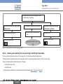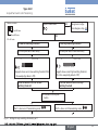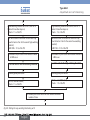
1
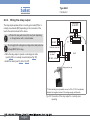
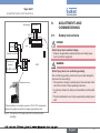
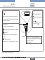
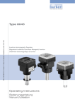
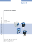
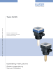
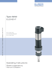
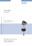
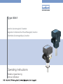
Type 8041
Insertion electromagnetic flowmeter
Magnetisch-induktives Durchfluss-Messgerät, Insertion
Débitmètre électromagnétique à insertion
Operating Instructions
Bedienungsanleitung
Manuel utilisateur
We reserve the right to make technical changes without notice.
Technische Änderungen vorbehalten.
Sous réserve de modifications techniques.
© Bürkert SAS, 2011 - 2013
Operating Instructions 1308/1_EU-ML_559777_Original_FR
Type 8041

1. About this manual..................................................................................3
6.4. General data........................................................................................ 11
1.1. Symbols used........................................................................................3
6.5. Electrical data..................................................................................... 12
1.2. Definition of the word "device".....................................................3
6.6. Electrical connections.................................................................... 13
2. Intended use.................................................................................................4
6.7. K factors................................................................................................. 13
3. Basic safety information................................................................4
7. Quick installation............................................................................... 14
4. General information............................................................................6
8. INstallation................................................................................................ 16
4.1. Manufacturer's address and international contacts..........6
8.1. Safety instructions........................................................................... 16
4.2. Warranty conditions............................................................................6
8.2. Installation onto the pipe.............................................................. 17
4.3. Information on the Internet.............................................................6
8.2.1. Recommandations for installing the 8041 on
the pipe...................................................................................17
5. Description....................................................................................................6
8.2.2. Installation into the pipe of a 8041 with a G2'' nut......20
5.1. Area of application..............................................................................6
5.2. General description............................................................................6
8.2.3. Installation into the pipe of a 8041 with a clamp
connection.............................................................................21
5.2.1. Construction............................................................................ 6
8.3. Wiring....................................................................................................... 21
5.2.2. Operating principle................................................................ 6
8.3.1. Wiring the 4-20 mA output...............................................24
5.3. Description of the name plate......................................................7
8.3.2. Wiring the frequency output..............................................24
5.4. Available versions................................................................................7
8.3.3. Wiring the relay output.......................................................26
6. Technical data............................................................................................8
9. Adjustment and commissioning............................................. 27
6.1. Conditions of use.................................................................................8
9.1. Safety instructions........................................................................... 27
6.2. Conformity to standards and directives..................................8
9.2. Description of the electronic board........................................ 28
6.3. Mechanical data....................................................................................8
9.3. General diagram of the Read and
English
1
Type 8041

Parameterizing modes................................................................... 30
9.4. Selecting the frequency of the main supply...................... 32
9.5. Filter selection.................................................................................... 32
9.6. Selecting the measurement range.......................................... 33
9.7. Calibrating the flow zero point.................................................. 33
9.8. Calibrating the full scale............................................................... 36
9.9. Setting the parameters of the relay output........................ 39
9.9.1. Choosing the switching way of the relay output...........40
9.9.2. Viewing and setting the low and high switching
thresholds..............................................................................42
9.9.3. Viewing and setting the time delay before switching..45
10. Maintenance and troubleshooting................................. 48
10.1.Safety instructions........................................................................... 48
10.2.Cleaning the device......................................................................... 48
10.3.Cleaning the electrodes................................................................ 48
10.4.Replacing the seal on a device with G2" nut..................... 49
10.5.If you encounter problems........................................................... 49
11. Spare parts and accessories................................................ 53
12. Packaging, Transport.................................................................... 54
13. Storage........................................................................................................ 54
2
English
14. Disposal of the device.................................................................. 54
Type 8041
About this manual
1.
About this manual
This manual describes the entire life cycle of the device. Please keep
this manual in a safe place, accessible to all users and any new owners.
note
Warns against material damage.
• Failure to observe this warning may result in damage to the device
or system.
This manual contains important safety information.
Indicates additional information, advice or important
recommendations.
Failure to comply with these instructions can lead to hazardous
situations.
• This manual must be read and understood.
1.1.
Refers to information contained in this manual or in other
documents.
Symbols used
danger
Warns against an imminent danger.
• Failure to observe this warning can result in death or in serious
injury.
→→Indicates a procedure to be done.
1.2.
Definition of the word "device"
The word "device" used within these operating instructions refers to
the flowmeter type 8041.
Warning
Warns against a potentially dangerous situation.
• Failure to observe this warning can result in serious injury or even
death.
attention
Warns against a possible risk.
• Failure to observe this warning can result in substantial or minor
injuries.
English
3
Type 8041
Intended use
2.
Intended use
Use of the device that does not comply with the instructions
could present risks to people, nearby installations and the
environment.
• The 8041 flowmeter is intended exclusively to measure the flow
rate in liquids.
• This device must be protected against electromagnetic interference, ultraviolet rays and, when installed outdoors, the effects of
climatic conditions.
• This device must be used in compliance with the characteristics
and commissioning and use conditions specified in the contractual documents and in the operating instructions.
• Requirements for the safe and proper operation of the device
are proper transport, storage and installation, as well as careful
operation and maintenance.
• Only use the device as intended.
→→Observe any existing restraints when the device is exported.
3 .
Bas i c sa f et y
i n f o r mati o n
This safety information does not take into account:
• any contingencies or occurences that may arise during installation,
use and maintenance of the devices.
• the local safety regulations for which the operating company
is responsible including the staff in charge of installation and
maintenance.
Danger due to high pressure in the installation.
Danger due to electrical voltage.
Danger due to high temperatures of the fluid.
Danger due to the nature of the fluid.
Various dangerous situations
To avoid injury take care:
• to prevent any unintentional power supply switch-on.
• to ensure that installation and maintenance work are
carried out by qualified, authorised personnel in possession of
the appropriate tools.
• to guarantee a defined or controlled restarting of the process,
after a power supply interruption.
4
English
Type 8041
Basic safety information
note
Various dangerous situations (cont'd)
To avoid injury take care:
• not to use the device for the measurement of gas flow rates.
• not to use the device in explosive atmospheres.
• not to use the device in an environment incompatible with the
materials it is made of.
• not to subject the device to mechanical loads (e.g. by placing
objects on top of it or by using it as a step).
• not to make any external or internal modifications to the device.
• to use the device only if in perfect working order and in compliance with the instructions provided in these operating
instructions.
• to observe the general technical rules when installing and using
the device.
Elements / Components sensitive to electrostatic discharges
• This device contains electronic components sensitive to electrostatic discharges. They may be damaged if they are touched by
an electrostatically charged person or object. In the worst case
scenario, these components are instantly destroyed or go out of
order as soon as they are activated.
• To minimise or even avoid all damage due to an electrostatic
discharge, take all the precautions described in the EN 613405-1 and 5-2 norms.
• Also ensure that you do not touch any of the live electrical
components.
note
The device may be damaged by the fluid in contact with.
• Systematically check the chemical compatibility of the component materials of the device and the fluids likely to come into
contact with it (for example: alcohols, strong or concentrated
acids, aldehydes, alkaline compounds, esters, aliphatic compounds, ketones, halogenated aromatics or hydrocarbons,
oxidants and chlorinated agents).
English
5
Type 8041
General information
4.
General information
5.
Description
4.1.
Manufacturer's address and
international contacts
5.1.
Area of application
To contact the manufacturer of the device, use following address:
Bürkert SAS
Rue du Giessen
The device is used to measure the flow of neutral or slightly aggressive
fluids with a conductivity of more than 20 µS/cm in DN06 to DN400
pipes.
5.2.
BP 21
F-67220 TRIEMBACH-AU-VAL
You may also contact your local Bürkert sales office.
General description
5.2.1. Construction
They can also be found on the Internet under:
The device comprises an electronic module and a PVDF or stainless
steel measurement sensor.
www.burkert.com
The flow sensor comprises two electrodes and a magnetic system.
4.2.
The connection of the device to the process is made depending on
the version, either by a G2'' nut or a clamp.
Warranty conditions
The condition governing the legal warranty is the conforming use of
the device in observance of the operating conditions specified in these
operating instructions.
4.3.
Information on the Internet
You can find the user manuals and technical data sheets regarding
the type 8041 at:
www.burkert.com
Electrical connection is made via two cable glands on a 6-pin terminal
block.
The device requires an 18-36 VDC power supply and has:
• a frequency output,
• a relay output,
• a 4-20 mA current output.
5.2.2. Operating principle
The magnetic system in the flow sensor generates a magnetic field
in the fluid, perpendicular to the flow direction, see Fig. 1. The electrodes on the flow sensor ensure electrical contact with the fluid.
6
English
Type 8041
Description
When the fluid flows over them, a voltage is measured between the
two electrodes. This voltage is proportional to the fluid velocity.
4.
5.
6.
7.
8.
Compact housing
Manufacturing code
Relay data
Conformity logo
Warning: Before using the device, take into account the technical specifications described in these operating instructions.
9. Current output
10.Serial number
11.Order code
Fig. 1: Operating principle of the flow sensor
5.3.
5.4.
Description of the name plate
Made in France
1
2
3
Flow
sensor
4
FLOW:8041- IND LONG SST
18-36V —/220mA 4-20mA REL:230VAC~/3A CO
SN/ 2135
00552780
W47MG
5
Short
Long
Short
Long
Clamp
1)
11
10 9
8
7
6
Available versions
Flow sensor
PVDF
Material
Seal of the flow
sensor
FKM
Stainless steel
Stainless steel
Stainless steel
FKM
FKM
EPDM or FEP 1)
Order code
558064
558065
552779
552780
564688
Ordered separately. See chap. 11.
Fig. 2: Name plate of the device (example)
1. Power supply / Max. consumption.
2. Measured value and type of the device
3. Specification of the flow sensor
English
7
Type 8041
Technical data
6.
Technical data
6.1.
Conditions of use
Ambient temperature
Air humidity
Protection class acc. to
EN 60529
Degree of pollution
Installation category
Max height above see level
6.2.
-10 °C...+60 °C
< 80%, non condensated
IP65, with cable connected and
cable gland tightened and cover
screwed on to the electronic module
Degree 2 acc. to EN 61010-1
Category I acc. to EN 61010-1
2000 m
Conformity to standards and
directives
Type of fluid
Fluid group 1, par. 1.3.a
Fluid group 2 par. 1.3.a
Conditions
Forbidden
DN ≤ 32
Fluid group 1 par. 1.3.b
or DN > 32 and PNxDN ≤ 1000
PNxDN ≤ 2000
DN ≤ 200
Fluid group 2 par. 1.3.b
or PN ≤ 10
or PNxDN ≤ 5000
6.3.
Mechanical data
Table 1 : Wetted parts
Part
Holder of the flow sensor
The device conforms to the EC directives through the following
standards:
Electrodes
• EMC: EN 50081-1, EN 61000-6-2
Clamp (only clamp version)
• LVD: EN 61 010-1
Earthing ring (only if flow sensor holder in
PVDF)
Holder of the electrodes (only if flow
sensor holder in stainless steel)
Seal of the flow sensor (version with
G2" nut)
• Pressure: article 3§3 of the Pressure Directive 97/23/CE. Acc. to
the Pressure Directive 97/23/CE: the device can only be used in
the following cases (depending on the max. pressure, the DN of
the pipe and the fluid)
8
English
Material
PVDF or stainless steel
1.4404 / 316L
Stainless steel
1.4404 / 316L
Stainless steel
1.4404 / 316L
Stainless steel
1.4404 / 316L
PEEK
FKM (FDA approved)
Type 8041
Technical data
Table 2 : Parts not in contact with the fluid
Part
Housing, cover, nut
Material
• holder of the flow sensor in
stainless steel
• PPA, glass fiber reinforced
• holder of the flow sensor in
PVDF
Screws of the cover
Cable gland
Seal of the cover
Seal of the cable gland
• PC, glass fiber reinforced
Holder of the flow sensor
Electrodes
Electrodes holder
Stainless steel
PA
EPDM
Neoprene
Fig. 4: Parts of the flow sensor in stainless steel with a clamp
connection
116
Earthing ring
199
162
134
116
170
Holder of the
flow sensor
Electrodes
Fig. 3: Parts of the flow sensor holder in stainless steel (left) or in
PVDF (right), devices with a G2'' nut
88
88
Electrodes holder
Clamp
Fig. 5: Dimensions of the 8041 [mm]
English
9
Type 8041
Technical data
H
Table 3 : Dimension H in mm of the flowmeter 8041 with a G2" nut and inserted into an S020 fitting
Spigot, in plastic
T-fitting
DN6
DN8
DN15
DN20
DN25
DN32
DN40
DN50
DN65
DN80
DN100
DN110
DN125
DN150
DN180
DN200
DN250
DN300
DN350
DN400
10
163
163
168
166
166
169
173
179
179
Saddle
204
203
207
221
208
215
225
249
261
English
Welding tab with radius, in
stainless steel
187
193
200
169
174
180
185
195
233
242
206
217
263
281
293
306
321
238
298
317
329
Type 8041
Technical data
H
Table 4 : Dimension H in mm of the flowmeter 8041 with a clamp
connection and inserted into an S020 fitting
Welding socket
T-fitting
DN32
DN40
DN50
DN65
DN80
DN100
6.4.
181
186
191
199
205
211
181
186
191
199
205
211
General data
Fluid temperature
The fluid temperature may be
restricted by the fluid pressure and
the material of the S020 fitting used
(see Fig. 6 and Fig. 7).
• with holder of the flow
sensor in stainless steel
• -15...+150 °C
• with holder of the flow
sensor in PVDF
Fluid pressure
• 0...+80 °C
The fluid pressure may be restricted
by the fluid temperature, the material
of the S020 fitting used and the DN
of the S020 fitting used (see Fig. 6
and Fig. 7).
• with holder of the flow
sensor in stainless steel
• PN10 with a fitting in plastic,
PN16 with a fitting in metal
• with holder of the flow
sensor in PVDF
Flow rate measurement
• PN10
Pipe diameter
DN06 to DN400
• Measuring range
• 0,2 to 10 m/s 1)
Type of fitting
S020
• Linearity
• ±0,5% 1) of the full scale
Fluid conductivity
> 20 µS/cm
• Repeatability
• ±0,25% 1) of the measured value
• Accuracy with standard
K factor
• ±3,5% 1) of the measured value
• Accuracy with Teach-in
• ±0,5% 1) of the measured value
1)
Determined in the following reference conditions: fluid = water, water
and ambiant temperatures = 20 °C, upstream and downstream distances
respected, appropriate pipe dimensions
English
11
Type 8041
Technical data
P [bar]
P (bar)
16
15
14
13
12
11
10
9
8
7
6
5
4
3
2
1
0
PVDF (PN10) / Metal
10
9
8
PVC + PP
7
6
5
PVC (PN10)
4
3
PP (PN10)
2
1
0
+10
+30
+50
+70
T [°C]
Fig. 6: Fluid pressure-temperature dependency of the 8041 with a
flow sensor holder in PVDF, inserted into an S020 fitting in
metal, PVDF, PVC or PP
1)
English
PVDF
DN100 for measuring
devices with a clamp connection (PN10)
PVC + PP
PVDF (PN10)
PVC (PN10)
PP (PN10)
-20
0
+20 +40 +60 +80 +100 +120
+150
T (°C)
Except DN100 for measuring devices with a clamp connection
Fig. 7: Fluid pressure-temperature dependency of the 8041 with a
flow sensor holder in stainless steel, inserted into an S020
fitting in metal, PVDF, PVC or PP
6.5.
12
Metal
(PN16) 1)
Electrical data
Power supply
18-36 V DC, filtered and regulated
Current consumption
220 mA (at 18 V DC)
Power source (not
supplied)
limited energy source (in accordance to
UL 61010-1, paragraph 9.3)
Type 8041
Technical data
Current output
• Type of output
• 4-20 mA, sinking or sourcing wiring
• Accuracy
• ± 1% (0,16 mA)
• Refresh time
• 100 ms
• Max. loop impedance
• 1100 W at 36 V DC, 330 W at
18 V DC
Frequency output
• Frequency
• 0-240 Hz
• Duty cycle
• 50 % ± 1 %
• Max current
• 100 mA max.
• Protected against
short-circuits and
polarity reversal
Relay output
• yes
• Normally open or normally closed,
depending on the wiring
Cable specifications
• cable type
• Cross section
• Diameter of each cable:
• shielded
• 0,5 to 1,5 mm2
-- if only one cable is used
per cable gland
-- 6...12 mm
-- if two cables are used per
cable gland
-- 4 mm, with the supplied
multi-way seal
6.7.
K factors
The S020 fitting with weld end connections is available
in two versions: a version for the measuring devices with
a G2'' nut and a version for the measuring devices with a
clamp connection.
• Use the K factor of the fitting used.
• 3 A, 250 V AC max.
The device measures the flow velocity (in m/s) of the fluid and converts
it into a current (in mA) and a frequency rating (in Hz).
• Full scale exceeded
• 22 mA and 256 Hz
The current I or the frequency f are proportional to the flow rate Q (l/s),
the proportionality factor is called the "K factor":
• Error signal
• 22 mA and 0 Hz
Alarm
6.6.
Electrical connections
Type of connection
f = K1*Q
I = K2*Q + 4
with K1 and K2 in pulse/litre
Through two M20x1,5 cable
glands
English
13
Type 8041
Quick installation
The following formulae are used to calculate the K1 and K2 factors
needed to convert the current or frequency into a flow rate:
Full scale
K factor K1
K factor K2
10 m/s
K1 = 100 Kfitting
K2 = 20 3*Kfitting
5 m/s
K1 = 200 Kfitting
K2 = 40 3*Kfitting
2 m/s
K1 = 500 Kfitting
K2 = 100 3*Kfitting
where Kfitting = K factor of the S020 fitting used
Example:
If the full scale of the device is set to 5 m/s, the value of the current
output will be:
I = 40 Q + 4
7.
Quick installation
→→Unpack the device.
Order code
correct?
No
yes
→→
Loosen 4 screws and remove
cover.
→→Select the frequency of the main
supply with switch 1, see chap.
9.4.
3*Kfitting
with I in mA, Kfitting in pulse/litre and Q in l/s.
→→Select the filter with switches 2
and 3, see chap. 9.5.
→→Select the current output type,
see chap. 8.3.1.
14
English
Contact your Bürkert
agent
Type 8041
Quick installation
→→Select the measuring range with
switches 4 and 5, see chap. 9.6.
→→
Install the device on the
pipe.
→→Thread the cables through the
cable glands and make the connections to the electronic board,
see chap. 8.3.
No
Calibrate the full scale of
the installation?
yes
→→
Calibrate the full scale, see
chap. 9.8.
→→
Connect the shield on the
power cable to the earth, see
chap. 8.3.
The 10 bargraph LEDs
go ON?
No
→→Fill the pipe.
→→Energize the device.
→→
Calibrate the flow zero
point, see chap. 9.7.
→→ Make
sure the fluid
velocity > 2 m/s and
< 10 m/s.
yes
→→Set the relay output parameters,
see chap. 9.9.
English
15
Type 8041
INstallation
Green LED flashes once?
No, see chap. 10.5
8.
INstallation
8.1.
Safety instructions
danger
yes
→→Put the cover on the device as
dsecribed in Fig. 17, chap. 8.3.
Risk of injury due to high pressure in the installation.
• Stop the circulation of fluid, cut off the pressure and drain the
pipe before loosening the process connections.
Tighten the 4 screws of the
cover in an alternating pattern.
Risk of injury due to high fluid temperatures.
• Use safety gloves to handle the device.
• Stop the circulation of fluid and drain the pipe before loosening
the process connections.
The device is ready for use.
Risk of injury due to the nature of the fluid.
• Respect the prevailing regulations on accident prevention and
safety relating to the use of aggressive fluids.
→→
Risk of injury due to electrical voltage.
• Shut down the electrical power source of all the conductors and
isolate it before carrying out work on the system.
• Observe all applicable accident protection and safety regulations for electrical equipment.
16
English
Type 8041
INstallation
Warning
Risk of injury due to non-conforming installation.
• The electrical and fluid installation can only be carried out by
qualified and skilled staff with the appropriate tools.
• Install appropriate safety devices (correctly rated fuse and/or
circuit-breaker).
8.2.
Installation onto the pipe
8.2.1. Recommandations for installing the
8041 on the pipe
→→Choose a fitting appropriate to the velocity of the fluid inside the
pipe; refer to the graphs below:
Risk of injury due to unintentional switch on of power supply
or uncontrolled restarting of the installation.
• Take appropriate measures to avoid unintentional activation of
the installation.
• Guarantee a set or controlled restarting of the process subsequent to any intervention on the device.
Warning
Risk of injury if the fluid temperature/pressure dependency is
not respected.
• Observe the fluid temperature/pressure dependency according
to the nature of the material of the fitting used (see Fig. 6 and
Fig. 7).
English
17
18
English
0.05
0.1
0.2
0.5
1
2
5
10
20
5000
m3/h
0.2
0.5
1
2
5
10
20
50
100
200
500
1000
2000
3000
5000
10000
20000
1
0.5
3
1
Fluid velocity
0.3
0.3
0.5
0.01
0.1
0.02
0.05
0.1
0.2
0.5
1
2
5
10
20
50
100
200
500
1000
30000 2000
50000
l/min
100000
5
3
10
5
30 fps
fps
m/s
m/s
10
DN6
DN 6
DN 8
DN8
Example
DN15
(DN15
DN20)*
DN 15 (DN15
ou or
DN20)*
(DN40)*
DN32
DN 32 (DN40)*
DN 25 (DN32)*
DN25
(DN32)*
DN20
(DN25)*
DN 20 (DN25)*
DN40
(DN50)*
DN 40 (DN50)*
DN 80 (DN100)*
DN80
DN 65 (DN80)*
DN65
DN50
(DN65)*
DN 50 (DN65)*
DN 100
DN100
DN150
DN 150
DN 125
DN125
DN 400
DN400
DN 350
DN350
DN 300
DN300
DN 250
DN250
DN 200
DN200
* For the fittings:
- with external thread connections acc. to SMS 1145 ;
- with weld end connections acc. to SMS 3008, BS 4825 / ASME BPE
or DIN 11850 Range 2;
- with Clamp connections acc. to SMS 3017 / ISO 2852,
BS 4825 / ASME BPE or DIN 32676.
flow rate
50
100
200
500
1000
2000
5000
10000
20000
US gpm
Example:
- Specification: if the nominal flow rate is 10 m3/hthe ideal flow velocity is between
2 and 3 m/s
- Solution: intersection between flow rate and flow velocity in the graph gives the
appropriate pipe diameter, DN40 (or DN50 for the asterisked fittings).
INstallation
Type 8041
Type 8041
INstallation
→→Install the device on the pipe to have the upstream and downstream distances respected according to the design of the
pipes, refer to standard EN ISO 5167-1 and Fig. 8:
→→Respect the following additional mounting conditions to ensure
that the measuring device operates correctly:
-- We recommend to install the device at a 45° angle to the horizontal centre of the pipe to prevent deposits on the electrodes
and false measurements due to air bubbles (see Fig. 9);
45°
50 x DN 5 x DN
With control valve
40 x DN 5 x DN
Pipe with 2 elbows at 90° in
3 dimensions
45°
Fig. 9: Mounting angle on the pipe
25 x DN 5 x DN
Pipe with 2 elbows at 90°
20 x DN 5 x DN
Pipe with 1 elbow at 90° or
1 T-piece
-- Ensure that the pipe is always filled in the section around the
device (see Fig. 10).
-- When mounting vertically ensure that the flow direction is in an
upward direction (see Fig. 10).
-- Prevent the formation of air bubbles in the pipe in the section
around the device (see Fig. 11).
18 x DN 5 x DN
With pipe expansion
15 x DN 5 x DN
With pipe reduction
-- Always mount the device upstream a possible injection point
in the pipe of a high-conductivity fluid (for example: acid, base,
saline,...).
Horizontal mounting
Fig. 8: Upstream and downstream distances depending on the
design of the pipes.
Correct
English
Incorrect
19
Type 8041
INstallation
8.2.2. Installation into the pipe of a 8041
with a G2'' nut
Vertical mounting
flow direction
Correct
Observe the installation recommendations described at
chap. 8.2.1 and in the operating instructions of the S020.
→→Install the S020 fitting on the pipe.
→→Insert the nut (see mark 3, Fig. 12) on the fitting.
→→Insert the snap ring (mark 2, Fig. 12) into the groove (mark 5,
Incorrect
Fig. 10: Filling of the pipe
Fig. 12).
→→Position the cable glands parallel to the pipe and insert the
device (mark 1, Fig. 12) into the fitting.
Correct
Incorrect
→→Tighten the nut (mark 3, Fig. 12) by hand on the device.
flow direction
1
Correct
Incorrect
Fig. 11: Air bubbles within the pipe
→→If necessary, use a flow conditioner to improve measurement
Electrodes
precision.
2
3
5
4
Flow direction
Fig. 12: Installation into the pipe of the flowmeter with a G2'' nut
20
English
Type 8041
INstallation
8.2.3. Installation into the pipe of a 8041
with a clamp connection
Observe the installation recommendations described at
chap. 8.2.1 and in the operating instructions of the S020.
→→Install the S020 fitting on the pipe.
→→Install the seal (mark 1) on the
S020 fitting.
3
→→Make sure that the polarizing pin
(mark 2) is on the fitting.
→→Insert the device (mark 3) into
4
2
1
the fitting. Position the device in
order the arrow on the side of the
housing indicates the direction
of the flow: the totalizers will
increment.
→→Tighten by hand the clamp collar
(mark 4).
→→Charge the pipe to make sure the
installation is tight.
8.3.
Wiring
danger
Risk of injury due to electrical voltage.
• Shut down the electrical power source of all the conductors and
isolate it before carrying out work on the system.
• Observe all applicable accident protection and safety regulations for electrical equipment.
• Use a high quality electrical power supply (filtered and
regulated).
• Use cables with an operating temperature limit correct for
your application.
→→Protect the power supply by means of a 300 mA fuse
and a switch.
→→Do not install the cables near high voltage or high fre-
quency cables. If this cannot be avoided, observe a min.
distance of 30 cm.
→→Loosen the 4 screws of the cover to access the electronic board
of the device (see Fig. 14).
flow direction
Fig. 13: Installation into the pipe of a 8041 with a clamp connection
English
21
Type 8041
INstallation
Selector A : Sink/source
selector of the 4-20 mA
output
3
A
1
2
3 4
5 6
4...20 V+ V- PE Pls+ Pls-
1 Terminal block 3
B
2
Terminal 1: 4-20 mA output
C
NO
Terminal 2: V+ (positive
voltage)
NC
Connector 1: connection of the
flat cable coming from the flow
sensor (to energize the flow
sensor)
Terminal block 2: wiring the
relay output
C: common point
NO: normally open
Terminal 4: PE, shield of
the power supply cable;
Earth cable coming from the
housing and, second cable
on a version with flow sensor
holder in stainless steel (see
Fig. 15)
Terminal 5: Pls+, positive
frequency output
NC: normally closed
LED B : status LED of the relay
(LED ON = contact closed)
Fig. 14: Terminal assignment
22
Terminal 3: V- (power supply
ground)
Terminal 6: Pls-, negative
frequency output
English
Make sure the installation is equipotential (power supply
- 8041):
→→Connect together the various earth spots in the instal-
lation to eliminate the potential differences that may occur
between two earthes.
→→In the housing, connect the power supply cable shield to
terminal no. 4 of the electronic board connector (Fig. 15).
On a version with stainless steel flow sensor, a second
cable is coming from the sensor.
→→Connect the negative power supply terminal to the earth
to suppress the effects of common mode currents. If
this connection cannot be made directly, a 100 nF/50 V
capacitor can be connectec between the negative power
supply terminal and the earth (marked 1, Fig. 16).
• If the pipes are made of metal:
→→connect to the same earth the different metallic instru-
ments (valve, pump...) located near the device (marks 2,
Fig. 16).
• If the pipes are made of plastic:
→→insert the metal parts (not provided) in the plastic pipes,
upstream and downstream of the device (marked 2, Fig.
16).
→→connect the metal parts to the same earth (Fig. 16).
Type 8041
INstallation
note
Power cable shield
The device is not tight if only one or none of the cable glands
is used
• The device is only tight when the cable glands are either wired or
sealed. To seal a cable gland, do the following:
→→Loosen the nut of the unused cable gland.
→→Remove the transparent disk.
→→Insert the supplied stopper gasket.
→→Screw the nut of the cable gland.
→→Loosen the nuts of the cable glands.
→→Insert each cable through a nut than through a cable gland.
Power cable shield
1 2 3 4
Earth cable coming from the
housing
5 6
18-36 VDC
+
-
2
2
Power supply
1
Fig. 16: Earthing the device
→→Wire the 4-20 mA current output (see 8.3.1).
→→Wire the frequency output (see 8.3.2).
→→Wire the relay output (see 8.3.3).
→→Put the cover of the housing as described in Fig. 17.
→→Screw the 4 screws in an alternating pattern.
Second cable on a version with
a flow sensor holder in stainless
steel
Fig. 15: Earth connection terminal
Fig. 17: Position of the cover of the device
English
23
Type 8041
INstallation
8.3.1. Wiring the 4-20 mA output
The current output of the 8041 can be connected to a PLC or a
valve, either in sourcing mode or in sinking mode.
4-20 mA input
at external
instrument
→→Set the selector of the electronic board to the sourcing or the
in sinking mode (see Fig. 19).
→→Earth the device (see Fig. 18 or Fig. 19).
4-20 mA input
at external
instrument
Selector to
source
+
-
Power supply
18-36 VDC
*
I
1 2
3 4
5 6
4...20 V+ V- PE Pls+Pls* If direct earthing is not possible, connect a 100 nF / 50 V condensator
between the negative terminal of the voltage supply and the earth.
Fig. 18: Connection of the current output in sourcing mode
24
English
1 2
3 4
Power supply
18-36 VDC
5 6
4...20 V+ V- PE Pls+Pls-
300 mA
+
-
Selector to sink
+
-
*
I
sinking position (see Fig. 18 or Fig. 19).
→→Connect the 4-20 mA output in sourcing mode (see Fig. 18) or
300 mA
+
-
* If direct earthing is not possible, connect a 100 nF / 50 V condensator
between the negative terminal of the voltage supply and the earth.
Fig. 19: Connection of the current output in sinking mode
8.3.2. Wiring the frequency output
→→Connect the frequency output:
-- to a PLC in PNP or in NPN mode (see Fig. 20 and Fig. 21) ;
-- or to a load such as an electromechanical counter or a relay
(see Fig. 22),
-- or to a load such as an electronic counter with its own power
supply (see Fig. 23).
Type 8041
INstallation
V+ 0V
V+
Input
I
0V
I
8041
1 2 3 4
8041
1 2 3 4 5 6
5 6
4...20 V+ V- PE Pls+Pls4...20 V+ V- PE Pls+Pls-
Fig. 20: PNP connection of the frequency output to a PLC
Fig. 22: Connection of the frequency output to an electromechanical counter or a relay
V2
V1
GND2
GND1
V+
I
Input
0V
I
8041
1
2
3
4
8041
5
6
4...20 V+ V- PE Pls+
Pls-
1 2
3 4
5 6
4...20 V+ V- PE Pls+Pls-
Fig. 23: Connection of the frequency output to an electromechanical counter with its own power supply
Fig. 21: NPN connection of the frequency output to a PLC
English
25
Type 8041
INstallation
8.3.3. Wiring the relay output
Power supply
The relay output operates either in normally open mode (NO) or in
normally closed mode (NC), depending on the connection of the
load to the electronic board of the device.
18-36 VDC
+ 300 mA
→→Protect the relay with a fuse (3 A max.) and, depending
on the application, with a circuit breaker.
1 2 3 4 5 6
L
250 VAC N
Do not apply both a dangerous voltage and a safety extra low
voltage (SELV) to the relay.
→→Wire the relay output to operate in normally open mode
(see Fig. 24) or in normally closed mode (see Fig. 25).
→→Earth the device (see Fig. 24 or Fig. 25).
Protection circuit
Solenoid valve
(or alarm)
250 VAC, 3 A max.
*
4...20 V+ V- PE Pls+Pls-
3A
C
NO
NC
8041
Relay protection cap
* If direct earthing is not possible, connect a 100 nF / 50 V condensator
between the negative terminal of the voltage supply and the earth.
Fig. 24: Connection of the relay output for a normally open
operating
26
English
Type 8041
Adjustment and commissioning
Power supply
18-36 VDC
9.
Adjustment and
commissioning
9.1.
Safety instructions
+ 300 mA
*
1 2 3 4 5 6
L
250 VAC N
4...20 V+ V- PE Pls+Pls-
3A
Protection circuit
Solenoid valve
(or alarm)
250 VAC, 3 A max.
C
NO
NC
8041
danger
Risk of injury due to electrical voltage.
• Observe all applicable accident protection and safety regulations for electrical equipment.
Warning
Risk of injury due to non-conforming operating.
Relay protection cap
Non-conforming operating could lead to injuries and damage the
device and its surroundings.
• The operators in charge of operating must have read and understood the contents of these operating instructions.
• In particular, observe the safety recommendations and intended
use.
• The device/installation must only be operated by suitably trained
staff.
* If direct earthing is not possible, connect a 100 nF / 50 V condensator
between the negative terminal of the voltage supply and the earth.
Fig. 25: Connection of the relay output for a normally closed
operating
English
27
Type 8041
Adjustment and commissioning
9.2.
Warning
Danger due to non-conforming commissioning.
Non-conforming commissioning can lead to injuries and damage
the device and its surroundings.
• Before commissioning, make sure that the staff in charge have
read and fully understood the contents of these operating
instructions.
• In particular, observe the safety recommendations and intended
use.
• The device / the installation must only be commissioned by suitably trained staff.
note
The device may be damaged by the environment
• Protect this device against electromagnetic interference,
ultraviolet rays and, when installed outdoors, the effects of the
climatic conditions.
When the device is energized and if the cover is open,
there is no protection against electric shocks.
28
English
Description of the electronic
board
The device has 2 operating modes: the Read mode and the Parameterizing mode. The functions of each mode are summarised in the
following table.
Operating mode
Functions
Read
To view:
• the fluid velocity measured by the device;
• the values set for the relay function.
Parameterizing
• To calibrate the device.
• To set the relay parameters.
The 5 switches, the push-button, the green LED, the red LED
and the bargraph are used to set the parameters of the device
(see Fig. 26).
Type 8041
Adjustment and commissioning
Red led:
Green LED:
1 2
3 4
5 6
-
.....
Flashing once every second: the device is energized.
4...20 V+ V- PE Pls+Pls-
: device in Parameterizing
mode
Flashing once up to 5 times: to know which parameter
the bargraph is indicating
10-LED bargraph:
.....
flashing 1 up to 5
times: error (see 10.5)
1 2 3 4 5 6 7 8 9 10
1 LED ON = 10% of the full scale (or 10 seconds)
in Read mode
LED flashing "x" times = "x"% of the full scale (or "x"
seconds)
-
ON
-
123456
To view and set the device parameters:
-
: device in Read mode
in Parameterizing mode
LED flashing once = 1% of the full scale (or 1 second)
Push-button
Switches 1 to 5: to set the device parameters
(frequency of the main supply, filter of the measurements, measuring range)
Switch 6: unused
Fig. 26: Electronic board of the device
English
29
Type 8041
Adjustment and commissioning
9.3.
General diagram of the Read and Parameterizing modes
Read mode
Parameterizing mode
2
Calibration in progress
Flow zero calibration
alternately
Hold > 2 s
Full scale calibration
X
Release when
desired function is
displayed*
Confirm the choice
displayed
Hold > 2 s
1
* If no action for 10 s, the device goes back to Read mode, using the parameters from the previous adjustment.
30
English
Type 8041
Adjustment and commissioning
2
Relay
1
Hysteresis switching
Current way of
switching*
Hold > 2 s
Confirm the choice displayed
X
alternately
Release when
desired function is
displayed*
Window switching
Hold > 2 s
Short press
Current low switching
threshold*
Hold > 2 s
Current high switching
threshold*
Hold > 2 s
Unit increment: LED
flashes up to 9 times
Short press
Press and hold to
set the units
......
The LEDs then come
on one after the other
(increment in factors
of ten)
Unit increment: LED
flashes up to 9 times
Short press
2
Current time delay
before switching*
Hold > 2 s
X
Release
with the
desired unit is
reached*
X
Release with the
desired factor of
ten is reached*
Confirm the displayed value
Hold > 2 s
Repeat the sequence if necessary
Short press
* If no action for 10 s, the device goes back to Read mode, using the parameters from the previous adjustment.
English
31
Type 8041
Adjustment and commissioning
9.4.
Selecting the frequency of the
main supply
Switch 1 is used to select the frequency of the current provided by
the electricity network.
→→Position switch 1 to ON or OFF depending on the frequency of
When the filter is enabled, switch 3 is used to select the filter level:
slow or fast.
"Slow" filter is used to even out high variations in flow (example: fluid
containing air bubbles), see Fig. 27.
"Fast" filter is used to even out low variations in flow (see Fig. 27).
the main supply (see Fig. 26, chap. 9.2, and the following table).
Frequency of the power supplied by the network
Position of switch 1
50 Hz
OFF
60 Hz
ON
9.5.
Flow attenuated with fast filter
Actual flow rate
t (s)
Filter selection
The filter is used to attenuate the fluctuations in the flow indicated by
the bargraph and on the current and frequency outputs. The device
can operate with or without filter.
Flow attenuated with low filter
t (s)
→→Position switch 2 (see Fig. 26, chap. 9.2,
and the following
table) to activate or deactivate the filter feature.
Filter
Position of switch 2
disabled
OFF
enabled
ON
t (s)
Fig. 27: Flow filters
→→Position switch 3 to the filter level selected (see Fig. 26, and the
following table).
32
English
Type 8041
Adjustment and commissioning
9.7.
Calibrating the flow zero point
Filter
Position of switch 3
slow (Response time 10 to 90 % = 14 s)
OFF
→→Calibrate the device on commissioning and after each
ON
• Before calibrating the zero point on commissioning:
fast
(Response time 10 to 90 % = 5 s)
maintenance task.
→→immerse the measuring element in the fluid for 24 h
before calibration.
9.6.
Selecting the measurement
range
The output signal is proportional to the measured flow velocity.
Switches 4 and 5 are used to adjust the measuring range of the
device to your application.
→→Position switches 4 and 5 to select the measuring range (see
Fig. 26, and the following table).
After the measuring range has been modified, the percentages set for the low and high switching thresholds are
applied to the new full scale selected.
Measuring range
Position of
switch 4
Position of switch
5
0 to 2 m/s
ON
OFF
0 to 5 m/s
OFF
ON
0 to 10 m/s
OFF
OFF
0 to calibrated full scale
(between 2 and 10 m/s)
ON
ON
• Before calibrating the zero point after each maintenance
task:
→→immerse the measuring element in the fluid for 1 h before
calibration.
→→Before calibration, ensure that the pipe does not contain
any air bubbles and that the fluid is not moving.
→→Fill the pipe with fluid.
→→Stop the flow.
→→Calibrate the "zero flow" point (see Fig. 28 and Fig. 29).
English
33
Type 8041
Adjustment and commissioning
Device in Read mode?
Notation convention:
NO
See general configuration diagram,
chap. 9.3
.....
.....
Red LED state
Green LED state
YES
→→Press and hold the push
button.
After 2 s, device is in Parameterizing mode:
.....
Step 1
Bargraph alternates between:
Zero flow calibration
Full scale calibration
1 2 3 4 5 6 7 8 9 10
→→Release push button when
bargraph shows zero flow
calibration.
To calibrate automatically
A
Fig. 28: Calibration of the zero flow point, part 1
34
English
To select the calibration of the
other parameter
To go back to the Read mode
B
C
Type 8041
Adjustment and commissioning
B
A
To calibrate automatically
C
To select the calibration of the
other parameter
→→Briefly press push button.
→→Press and hold the push
To go back to the Read mode
→→Wait for 10 s.
button until...
Calibration in progress
End of calibration: red LED
goes off?
YES
Zero point stored.
Go back to Read mode.
.....
...bargraph goes back to step 1, Fig.
28
NO
Go back to Read mode
without confirming the
selection displayed.
Red LED flashes briefly
twice: zero point has not
been calibrated.
→→Briefly press push button
Go back to Read mode
using the zero point of the
previous calibration.
→→Check that the calibration
instructions are respected
(see beginning chap. 9.7).
→→Restart calibration
of the zero flow
point.
Fig. 29: Calibration of the zero flow point, part 2
English
35
Type 8041
Adjustment and commissioning
9.8.
Calibrating the full scale
The Fig. 30 and the Fig. 31 show the relation between the measured
fluid velocity and the value of the frequency or current provided by
the outputs.
Full scale error
mA
22
20
Full scale error
Hz
4
256
240
0
m/s
0.1
Calibrated full scale
0
Fig. 31: Relation between the measured fluid velocity and the value
of the current output
m/s
0.1
Calibrated full scale
Full scale + 20%
Fig. 30: Relation between the measured fluid velocity and the value
of the frequency output
36
Full scale + 20%
English
If no predefined measuring range is applicable to your process, the
device can be calibrated with the actual max. flow velocity of the
application.
The low bound of the measuring range is 0 m/s.
→→Position the switches 4 and 5 to ON (see Fig. 26, chap. 9.2).
→→Install the device on the pipe as described in chap. 8.
→→Allow the fluid to circulate in the pipe at maximum velocity.
→→Calibrate the full scale, see Fig. 32 and Fig. 33.
Type 8041
Adjustment and commissioning
Device in Read mode?
Notation convention:
NO
See general configuration diagram,
chap. 9.3
.....
.....
Red LED state
YES
Green LED state
→→Press and hold the push
button.
After 2 s, device is in Parameterizing mode:
.....
Step 1
Bargraph alternates between:
Zero flow calibration
Full scale calibration
1 2 3 4 5 6 7 8 9 10
→→Release push button when
bargraph shows full scale
calibration.
To calibrate automatically
A
To select the calibration of
the other parameter
B
To go back to the Read mode
C
Fig. 32: Calibration of the full scale, part 1
English
37
Type 8041
Adjustment and commissioning
B
A
To calibrate automatically
To select the calibration of the
other parameter
→→Briefly press push button.
→→Press and hold the push
button until...
Calibration in progress
...bargraph goes back to step
1, Fig. 32
End of calibration: red LED
goes off?
NO
Red LED flashes:
4 times: fluid velocity < 2 m/s
YES
Full scale value stored
5 times: fluid velocity < 10 m/s
Go back to Read mode
→→Press push button for 2 s.
The full scale cannot be calibrated
.....
Go back to Read mode using the
full scale selected or previously
calibrated.
Fig. 33: Calibration of the full scale, part 2
38
English
C
To go back to the Read mode
→→Wait for 10 s.
Go back to Read mode without confirming the selection displayed.
Type 8041
Adjustment and commissioning
9.9.
Setting the parameters of the relay output
The Fig. 34 shows the behaviour of the relay output depending on the parameter settings and the measured velocity.
m/s
High threshold
Low threshold
2s
2s
2s
t
Connection of the relay output
Hysteresis switching
NO-wired relay
Switching time-out = 0 s
NC-wired relay
NO-wired relay
Switching time-out = 2 s
NC-wired relay
Window switching
NO-wired relay
Switching time-out = 0 s
NC-wired relay
Switching time-out = 2 s
NO-wired relay
NC-wired relay
Relay
activated
deactivated
activated
deactivated
activated
deactivated
activated
deactivated
activated
deactivated
activated
deactivated
activated
deactivated
activated
deactivated
Fig. 34: Behaviour of the relay output depending on the parameter settings and the measured velocity
English
39
Type 8041
Adjustment and commissioning
The wiring of the relay determines the function of the relay:
Normally Open (NO) or Normally Closed (NC).
The following parameters of the relay output can be set:
-- the switching way: window or hysteresis (see chap. 9.9.1)
-- the value of the low switching threshold, as a percentage of the
full scale (see chap. 9.9.2)
-- the value of the high switching threshold, as a percentage of
the full scale (see chap. 9.9.2)
-- the time delay before switching: from 0 to 100 seconds (see
chap. 9.9.3).
9.9.1. Choosing the switching way of the
relay output
Two switching ways of the relay are available, window or hysteresis.
In window switching, the state of the relay output is changed
whenever one of the thresholds is detected (see Fig. 35 and Fig.
36).
actived
Low threshold
English
deactivated
Low threshold
m/s
High threshold
Fig. 36: Change of state of the relay output in window switching
with a relay wired as NC
In hysteresis switching (see Fig. 37 and Fig. 38), the state of the
relay output is changed:
• when both the high threshold is detected and the fluid velocity
increases;
• when both the low threshold is detected and the fluid velocity
decreases;
State of the relay output
actived
deactivated
m/s
High threshold
Fig. 37: Change of state of the relay output in hysteresis switching
with a relay wired as NO
m/s
High threshold
Fig. 35: Change of state of the relay output in window switching
with a relay wired as NO
40
actived
Low threshold
State of the relay output
deactivated
State of the relay output
Type 8041
Adjustment and commissioning
State of the relay output
Device in Read mode?
actived
NO
.....
deactivated
Low threshold
m/s
High threshold
Fig. 38: Change of state of the relay output in hysteresis switching
with a relay wired as NC
See general configuration diagram,
chap. 9.3
YES
→→1 short press on push button.
→→Select the way of switching of the relay (see Fig. 39 and Fig.
40).
1
2 3 4 5 6 7 8 9 10
Bargraph shows current way of switching (Hysteresis,
by default)
→→Press and hold the push button.
Notation convention for the following diagram:
.....
Red LED state
Green LED state
After 2 s, device is in Parameterizing mode:
.....
Bargraph alternates between:
Hysteresis switching
Window switching
1 2 3 4 5 6 7 8 9 10
Step 1
Fig. 39: Choosing the relay switching way, part 1
English
41
Type 8041
Adjustment and commissioning
→→Release push button when bargraph shows
desired way of switching.
To confirm the selection and go back
to Read mode
→→Briefly press push button.
To choose the other way of switching
→→Press and hold the push button
until...
To go back to Read mode without
confirming the selection
→→Wait for 10 s.
Go back to Read mode
Go back to Read mode
...bargraph goes back to step 1, Fig.
39
.....
.....
Fig. 40: Choosing the relay switching way, part 2
9.9.2. Viewing and setting the low and high switching thresholds
The low switching threshold can be set in the range from 0 to the high switching threshold value.
The high switching threshold can be set in the range from the low switching threshold value to 100% of the full scale.
The low and high switching thresholds are set in 2 steps:
-- setting the factors of ten;
-- setting the units.
→→Viewing and/or setting the low and high switching thresholds (see Fig. 41, Fig. 42 and Fig. 43).
42
English
Type 8041
Adjustment and commissioning
Device in Read mode?
Notation convention:
.....
NO
.....
Red LED state
Green LED state
See general configuration diagram, chap. 9.3
YES
FS = Full scale
To view low switching threshold
To view high switching threshold
→→Press push button twice briefly
→→Press push button three times briefly
0
0
100 % FS
100 % FS
1 2 3 4 5 6 7 8 910
1 2 3 4 5 6 7 8 910
Bargraph shows current low switching threshold, 24%
in the example (by default = FS)
To set the factors of ten for the low
switching threshold
Bargraph shows current high switching threshold,
82% in the example (by default = FS)
To set the factors of ten for the high
switching threshold
→→Press and hold the push
button.
After 2 s, device is in Parameterizing mode:
A
After 2 s, device is in Parameterizing mode:
B
Fig. 41: Setting the relay switching thresholds, part 1
English
43
Type 8041
Adjustment and commissioning
A
If low switching threshold set to 24%, LED no. 3
flashes 9 times then stays on;
1 flash = 1 % of the FS
B
If high switching threshold set to 82%, LED no. 9
flashes 9 times then stays on;
1 flash = 1 % of the FS
Next LEDS come on one after the other until they
show the factor of ten for the current high switching
threshold;
1 LED ON = 10 % of the FS
Next LEDS come on one after the other until they
show the factor of ten for the current low switching
threshold;
→→Release the push button when desired number
→→Release the push button when desired number of
To set the units for the low switching threshold.
To set the units for the high switching threshold.
→→Briefly press push button
→→Briefly press push button
After 2 s, next LED flashes;
1 flash = 1 % of the FS
After 2 s, next LED flashes;
1 flash = 1 % of the FS
1 LED ON = 10 % of the FS
LEDs is on.
of LEDs is on.
→→Release push button when LED has flashed the desired
number of times
C
Fig. 42: Setting the relay switching thresholds, part 2
44
English
Type 8041
Adjustment and commissioning
C
To confirm the selection and go
back to Read mode
To modify the value displayed
→→Briefly press push button.
→→Press and hold the push
Go back to Read mode
→→Release the push button
button
.....
when desired number of
LEDs is on
To go back to Read mode
without confirming the value set.
→→Wait for 10 s.
Go back to Read mode
.....
Fig. 43: Setting the relay switching thresholds, part 3
9.9.3. Viewing and setting the time delay before switching
Switching occurs if one of the thresholds (low, high) is exceeded for a period longer than the set time delay. The time delay applies to both
switching thresholds.
The time delay before switching must be set to between 0 and 100 s. If the time delay is equal to 0, switching occurs immediately.
The time delay before switching is set in 2 steps:
-- setting the factors of ten for the seconds;
-- setting the seconds.
→→Viewing and/or setting the time delay before switching (see Fig. 44, Fig. 45 and Fig. 46).
English
45
Type 8041
Adjustment and commissioning
Notation convention:
.....
A
Red LED state
Green LED state
Device in Read mode?
NO
.....
YES
To view time delay before switching
If time delay before switching set to 52 s, LED
no. 6 flashes 9 times then stays on
See general configuration diagram,
chap. 9.3
Next LEDs come on one after the other
→→Release the push button when desired
number of LEDs is on.
1 LED ON = 10 s
→→Press push button four times briefly
0s
100 s
To set the seconds of the time delay before
switching
1 2 3 4 5 6 7 8 910
→→Press and hold the push button
Bargraph shows current time delay before switching, 52 s in
the example (by default = 100 s)
After 2 s, next LED flashes
1 flash = 1 s
To set the factors of ten for the seconds of the time delay
before switching
→→Release push button when LED has flashed
→→Press and hold the push button
the desired number of times
After 2 s, device is in Parameterizing mode:
A
Fig. 44: Setting the time delay before relay switching, part 1
46
English
B
C
Fig. 45: Setting the time delay before relay switching, part 2
D
Type 8041
Adjustment and commissioning
D
C
B
To go back to Read mode without
confirming the value set.
To modify the seconds of the
time delay before switching.
→→Briefly press push button.
→→Press and hold the push
button
To go back to Read mode without
confirming the value set.
→→Wait for 10 s.
→→Release push button when
LED has flashed the desired
number of times
Fig. 46: Setting the time delay before relay switching, part 3
English
47
Type 8041
Maintenance and troubleshooting
10.
Maintenance and
troubleshooting
10.1. Safety instructions
danger
Risk of injury due to high pressure in the installation.
• Stop the circulation of fluid, cut off the pressure and drain the
pipe before loosening the process connections.
Risk of injury due to high fluid temperatures.
• Use safety gloves to handle the device.
• Stop the circulation of fluid and drain the pipe before loosening
the process connections.
Risk of injury due to the nature of the fluid.
• Respect the prevailing regulations on accident prevention and
safety relating to the use of aggressive fluids.
Risk of injury due to electrical voltage.
• Shut down the electrical power source of all the conductors and
isolate it before carrying out work on the system.
• Observe all applicable accident protection and safety regulations for electrical equipment.
48
English
Warning
Risk of injury due to non-conforming maintenance.
• Maintenance must only be carried out by qualified and skilled
staff with the appropriate tools.
• Guarantee a set or controlled restarting of the process subsequent to any intervention.
10.2. Cleaning the device
note
The device may be damaged by the cleaning product.
• Clean the device with a cloth dampened with water or a detergent compatible with the materials the device is made of.
• Do not use any abrasive acting materials.
10.3. Cleaning the electrodes
note
Dirt on the electrodes may cause measurement errors.
• Regularly clean the wetted parts.
• Rinse the electrodes after cleaning.
Type 8041
Maintenance and troubleshooting
10.4. Replacing the seal on a device
with G2" nut
10.5. If you encounter problems
danger
note
Risk of injury due to high pressure in the installation.
• Stop the circulation of fluid and cut off the pressure before
loosening the process connections.
Do not scratch the seal groove.
Risk of injury due to electrical voltage.
• Shut down the electrical power source of all the conductors and
isolate it before carrying out work on the system.
• Observe all applicable accident protection and safety regulations for electrical equipment.
1
2
Seal
3
Fig. 47: Dismounting the device and location of the seal
→→Loosen the nut of the device (mark 2).
→→Remove the device from the fitting (mark 1).
→→Remove the seal from the groove.
→→Clean the seal groove.
→→Insert the new O-ring in the groove (see chap. 11).
→→Insert the device into the fitting.
→→Tighten the nut (mark 2) by hand on the device.
Groove
Risk of injury due to high fluid temperatures.
• Use safety gloves to handle the device.
• Stop the circulation of fluid and drain the pipe before loosening
the process connections.
Risk of injury due to the nature of the fluid.
• Respect the prevailing regulations on accident prevention and
safety relating to the use of aggressive fluids.
English
49
Type 8041
Maintenance and troubleshooting
Problem
Bargraph
state
The device
does not
respond
OFF
The device
does not
respond
OFF
Current or
frequency
Meaning / Cause
output
state
Flashes once
Flashes once 22 mA and Measuring range
briefly every 2 s every second 256 Hz
exceeded by more than
20%
Green LED
Red LED state
state
Flashes twice Flashes once 22 mA and The flow zero point calibriefly every 2 s every second 0 Hz
bration failed.
Recommended action
→→Clear the error by briefly pressing the
push-button.
→→Consult the graphs (see chap.
8.2.1).
→→Clear the error by briefly pressing the
push-button.
→→Check upstream/downstream distances (see chap. 8.2.1).
→→Restart the calibration (see chap.
9.7).
→→If the error persists, contact your
The device
does not
respond
The device
does not
respond
Bürkert retailer.
OFF
Flashes 3 times Flashes once 22 mA and The device is out of
briefly every 2 s every second 0 Hz
service
→→Contact your Bürkert retailer.
OFF
Flashes 4 times Flashes once 22 mA and The full scale calibration
briefly every 2 s every second 0 Hz
failed because the fluid
velocity < 2 m/s
→→Clear the error by briefly pressing the
push-button.
→→Check the fluid velocity.
→→Restart the calibration of the full
scale (see chap. 9.8).
50
English
Type 8041
Maintenance and troubleshooting
Problem
Bargraph
state
The device
does not
respond
OFF
The sensor
does not
work
OFF
Current or
frequency
Meaning / Cause
output
state
Flashes 5 times Flashes once 22 mA and The calibration of the full
briefly every 2 s every second 0 Hz
scale failed because the
fluid velocity > 10 m/s.
Green LED
Red LED state
state
OFF
OFF
0 mA
and
0 Hz
-
Incorrect flow measurement.
All the
LEDs are
ON
OFF
OFF
Flashes irreg- 0 mA
ularly or is off and
0 Hz
OFF
0 mA
and
0 Hz
Flashes once every second
Flashes once 20 mA and
every second 240 Hz
The device is not
connected.
The fuse of the installation
is in a bad condition
The switch of the installation is set to OFF
The power supply has
been wrong connected to
the + and - terminals
The power supply is not
stable.
Recommended action
→→Clear the error by briefly pressing the
push-button.
→→Check the fluid velocity.
→→Restart the calibration of the full
scale (see chap. 9.8).
→→Connect the device.
→→Replace the fuse.
→→Position the installation switch to ON.
→→Check the wiring (see chap. 8.3.1,
8.3.2, 8.3.3).
→→Replace the power supply.
The device is out of
service
→→Return the device to your Bürkert
The K factor has not been
correctly calculated.
Measuring range
exceeded by less than
20%.
→→Recalculate the K factor (see chap.
retailer.
6.7).
→→Select the higher measuring range
(see chap. 9.6)
English
51
Type 8041
Maintenance and troubleshooting
Problem
Bargraph
state
The flow rate Unstable
measurements are not
stable
Meaning / Cause
Recommended action
OFF
The electrodes are dirty.
→→Clean the electrodes (see chap.
The electrodes are not in
contact with the fluid.
Air bubbles appear in the
fluid.
→→Make sure the electrodes are always
The device
shows a
transmits no value
current or no
frequency at
all.
OFF
The sensor
Lit
does not
measure a nil
flow rate.
OFF
52
Current or
frequency
output
state
Flashes once > 4 mA
every second and
> 0 Hz
Green LED
Red LED state
state
The flow sensor has not
been immersed for 24 h
before calibration of the
"flow zero" point.
The flow rate fluctuations
are very important.
Upstream-downstream
connection has not been
correctly done.
Flashes once 0 mA and/or The position of the sink/
every second 0 Hz
source selector is not
correct.
The outputs are not correctly wired.
English
Flashes once > 4 mA and The calibration of the flow
every second > 0 Hz
zero point has not been
correctly done.
10.3).
in contact with the fluid
→→Respect the mounting recommendations (see chap. 8.2).
→→Select the "slow" filter (see chap.
9.5).
→→Respect the calibration procedure
(see chap. 9.7).
→→Select the "slow" filter (see chap.
9.5).
→→Respect the mounting recommendations (see chap. 8.2).
→→Correctly position the sink/source
selector (see chap. 8.3.1).
→→Check the wiring of the outputs (see
chap. 8.3.1, 8.3.2, 8.3.3).
→→Calibrate again (see chap. 9.7).
Type 8041
Spare parts and accessories
11.
Spare parts and
accessories
Spare parts
Set of:
Order code
558102
-- 1 stopper gasket for an M20x1.5 cable gland
attention
-- 1 multiway seal, 2x6 mm, for cable gland
Risk of injury and/or damage caused by the use of unsuitable
parts.
Incorrect accessories and unsuitable replacement parts may
cause injuries and damage the device and the surrounding area.
• Use only original accessories and original spare parts from
Bürkert.
Spare parts
Set of:
Order code
449755
-- 2 M20x1.5 cable glands
-- 2 neoprene flat seals for cable glands
-- 2 M20x1.5 screw plugs
619205
PPA nut
PC nut
Set of:
440229
619204
552111
-- 1 green FKM seal
552812
-- Terminal block
-- 2 M20x1.5 screw plugs
-- 2 M20x1,5 / NPT 1/2" reductions
-- 1 mounting instruction sheet
Snap ring
-- 1 black EPDM seal
Relay connection kit with:
-- 2 neoprene flat seals for cable glands or a
screw plugs
-- 2 multiway seals 2x6 mm
Set of:
-- 1 green FKM seal for the flow sensor of a
8041 with G2'' nut
-- 1 protective cap
551782
-- 1 cable clip
-- 1 mounting instruction sheet
EPDM seal with FDA agreement (for a 8041 with a
clamp connection)
FEP seal with FDA agreement (for a 8041 with a
clamp connection)
Clamp collar
English
730837
730839
731164
53
Type 8041
Storage
Spare parts
Set of:
Order code
565384
-- 1 stopper gasket for an M20 x 1,5 cable gland
-- 1 multi-way seal, 2 x 6 mm, for a cable gland
12.
Packaging, Transport
attention
13.
attention
Poor storage can damage the device.
• Store the device in a dry place away from dust.
• Storage temperature: -20...+60 °C.
• Humidity: < 80%, non condensated.
14.
Damage due to transport
Transport may damage an insufficiently protected device.
• Transport the device in shock-resistant packaging and away
from humidity and dirt.
• Do not expose the device to temperatures outside the admissible storage temperature range.
• Protect the electrical interfaces using protective plugs.
Storage
Disposal of the device
→→Dispose of the device and its packaging in an environmentallyfriendly way.
attention
Damage to the environment caused by products contaminated by fluids.
• Keep to the existing provisions on the subject of waste disposal
and environmental protection.
Note:
Comply with the national and/or local regulations which
concern the area of waste disposal.
54
English
Type 8041

English
55
Type 8041

56
English
www.burkert.com