1
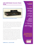
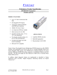
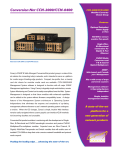
Application Note 257
best Practices for troubleshooting WDm networks with
an optical spectrum analyzer
by Jean-Sébastien Tassé, Product Line Manager, EXFO
the challenge
Most telecom operators are facing a growing demand for
bandwidth, which is fueled by data-hungry applications such as
video-conferencing, IPTV, video on demand, etc., while the average
revenue per-user is reaching its plateau. These trends lead to
significant pressure to increase efficiency in field operations, avoid
repeat truck rolls and develop network test procedures to get it right
the first time in order to reduce operating expenses.
Wavelength division multiplexed (WDM) networks, in which several
wavelengths propagate in a single fiber, have been rolled out in
the vast majority of countries. These networks present a high
level of complexity, due to the large number of active and passive
components (i.e., transmitters, multiplexers, demultiplexers, etc.) that
must work properly to ensure top-notch quality of service (QoS).
λ1
2-degree
ROADM
λ1
n-degree
ROADM
λ2
λ2
λ2
λ3
λ2 λ1
tyPical sign calling for WDm netWorK
troubleshooting
A typical troubleshooting intervention with an OSA stems from an
alarm received at the network operation center (NOC). The table
below highlights the typical alarm and the component issuing them:
alarm
typical alarms
Amplifier
Automatic power reduction
Automatic power shutdown
Receiver
High bit error rate
Failure of one or several wavelengths
Transponder
Loss of signal
Table 1. Typical alarms
On top of alarms, some systems provide extra information like
the received power at each channel, the bit error rate (BER) per
channel, the input and output power at each amplifier, etc. Although
not specifically part of the alarm, this kind of information can be
extremely valuable to determine what to test and where.
Where to troubleshoot?
λ3
λ3
λ1
Figure 1. Example of a WDM network with ROADMs
While more basic problems call for a relatively straightforward
solution (i.e., no transmission between points A and B requires an
OTDR to pinpoint the exact location of the failure), more complex
problems like a missing channel or high noise level require the use
of more advanced troubleshooting tools like an optical spectrum
analyzer (OSA) to rapidly find and fix an issue.
However, most telecom operators do not have troubleshooting
procedures, so field technicians are left wondering what and
where to test, and what to do with the results. As a consequence,
troubleshooting is often done by a senior field technician—with the
help of one of the few field team managers that has an in-depth
understanding of WDM networks and OSAs. In this paper, we will
discuss some of the best practices used by operators to troubleshoot
a WDM network with an OSA in order to resolve any breakdown as
quickly and efficiently as possible.
Let’s assume that the issue has occured for the first time. The
location of the first OSA test depends on technical considerations
like the network component that issued the alarm and the
likely technical cause of the trouble, as well as on operational
considerations like the availability of field technicians and
equipment.
In an ideal case, the likely defective component is readily known
(from the alarm origin or from the system information previously
mentioned), and the first OSA tests will be done at the input and
output of this component to confirm the fault. If one does not know
which component failed, the first question to answer is whether
the breakdown affects all wavelengths or just one or two. If it
affects them all, then it is a broadband device that has issues: an
amplifier or the fiber itself. If only one or two wavelengths have
failed and the defective component is unknown, then it is better to
start troubleshooting with an OSA from the receiver end because
a measurement at this location takes into account everything
that happened during transmission. It is then possible to work
backwards to the transmitter end, acquiring an OSA trace at each
major component location.
Application Note 257
Defective
component
is unknown
Defective
component
is known
Issue affecting one
or two wavelenghts
Issue affecting
all wavelenghts
Start troubleshooting
from receiver
Continue troubleshooting
towards transmitter
Check fiber and
amplifiers
Test input and output
of defective component
Figure 2. Where to troubleshoot
In the case that the issue is recurring and cannot easily be fixed, then
a monitoring solution should be considered.
What Parameters shoulD be testeD
at each location?
The list of parameters tested depends on the component that is being
tested and the likely cause. For instance, if the breakdown occurred in
a CWDM (coarse WDM) cellular backhaul without any amplifiers, then
a measurement of power and wavelength will be enough. In most other
cases, many operators tell us that they usually measure channel central
wavelength, power, flatness, optical signal-to-noise ratio (OSNR), and
sometimes channel spacing.
Channel central wavelength is defined as the wavelength center of
mass, i.e., the average wavelength of the signal power. Channel flatness,
the difference between the weakest and the most powerful channels,
is an important value to test because non-uniform channel power
will undergo different gains in amplifiers, which will further increase
the power difference between channels. Some operators rely on the
tolerance specified by the component manufacturer for channel flatness,
while others set a specific requirement internally. Acceptable ranges
used in the industry for channel flatness vary from 0.5 dB to 2.0 dB.
Channel power relates to the signal power of each wavelength, while
channel spacing measures the wavelength separation between two
channels. Depending on the DWDM (dense WDM) configuration, this
value can be 25, 33, 50 or 100 GHz.
Many operators also measure OSNR as a key parameter to assess the
quality of the transmission; there is a direct relationship between OSNR
and BER in systems without forward error correction (FEC), as long
as other impairments are not present (dispersion, non-linear effects,
etc.). A minimum OSNR of 15 dB is often required at the receiver, but
a value of at least 20 dB is often preferred. The IEC standard 612802-9 recommends that to properly measure OSNR, the OSA needs to
be able to measure 10 dB more than what is required; therefore, an
optical rejection ratio of 30 dB is required for 20 dB OSNR testing.
Parameter to test
acceptable Value
Channel central wavelength
Within the system’s acceptable
range for channel central wavelength
Channel power
Within the system’s acceptable
range for channel power
Channel (or power) flatness
Depends on the manufacturer
Typically 0.5 dB to 2 dB between
weakest and most powerful channel
Channel spacing
According to ITU grid of system
Typically 25, 50 or 100 GHz
Optical signal-to-noise ratio
>15 to 20 dB at the receiver
What are the common causes of failure?
There are a number of components that can fail, such as amplifiers,
transmitters, bulk heads and splices and optical add/drop
multiplexers (OADM). Amplifiers will often be in cause, because
they can exhibit wrong gain value due to aging or if the input power
is out of range, and they can also show gain tilt (gain not uniform in
a given spectral range). Transmitters might not work according to
specifications due to wavelength drift, wrong output power level,
etc. Bulk heads and splices, another common source of failure,
might show losses above the specified tolerance, which is why an
inspection probe is a valuable instrument to include in every field
technician’s arsenal.
OADMs and ROADMs (reconfigurable OADMs) usually exhibit good
stability, though they can at times cause issues. Multiplexers and
demultiplexers are also stable because they are passive components.
If they work properly at turn-up, they will not deteriorate over time,
especially since they are generally used in well-controlled environments
like central offices. Passive components, if installed properly, seldom
cause issues, while active ones can degrade over time.
Defective component
type of failure
frequency
Amplifier
Wrong gain due to aging
Average
Amplifier
Wrong gain due to input
power out of range
Often
Amplifier
Gain tilt
Average
Bulk heads and splices
Excessive loss
Very often
Transmitter
Wavelength drift
Sometimes
Transmitter
Power drift
Sometimes
ROADM
Wrong wavelength assignment
(configuration issue)
Sometimes
MUX and DEMUX
Wrong MUX/DEMUX installed
Very rare
Table 3. Common causes of failures
Practical consiDeration: monitoring Ports
One of the challenges of troubleshooting WDM networks is that,
in most cases, there is live traffic on the fibers that cannot easily
be turned off or re-routed. Monitoring ports that enable a field
technician to make an OSA measurement without stopping the
traffic are critical. In general, amplifiers have monitoring ports, but
multiplexers and demultiplexers do not—especially the older ones.
One can circumvent the lack of a monitoring port by using a previous
port, in particular if there are only passive elements between the
two monitoring ports; traffic can also be re-routed, though this is
not ideal. Fortunately, the trend is now to include monitoring ports
in most components.
Also, the ratio between the power at the monitoring port and within
the fiber varies from one port to the other, and it is not always known
(sometimes the tap loss is written on the device). This variability
becomes important to consider if a field technician is interested
in absolute measurements, but if he wants to make relative
measurements (e.g., measure channel flatness), which is the most
common case, the variability becomes unimportant since the relative
signal powers are independent of the monitoring port properties.
According to system specifications
for other locations.
Table 2. Parameters to test with an OSA and acceptable values
© 2011 EXFO Inc. All rights reserved.
Application Note 257
Detailed Troubleshooting Procedures for Different Types of Alarms and Failures
Now that we have discussed the general principles, let us take a closer look at specific alarms and failures and propose a troubleshooting
procedure for each of them. Please note that functionalities like gain tilt control in amplifiers or equalization in ROADMs can affect the signal,
and therefore have an impact on the procedures described below.
Case 1 |
Power-Related Problem Affecting All Wavelengths, Excluding High BER
Such an issue can arise from a fiber cut, excessive loss (e.g., a dirty connector) somewhere in the light path, or a
bad amplifier (defective or poorly configured).
Procedure:
Case 2 |
1. Carefully analyze the alarm from the equipment management system (EMS), as they transmit from one amplifier to the
next an amplifier signal that is out-of-band. If the EMS signal gets through, then the likely cause is a defective or poorly
configured amplifier. Test the amplifier gain. If the EMS signal does not get through, then the probable cause is a fiber
break or excessive loss.
2. Go to a place downstream from the location of the suspected failure. If the fault location cannot be guessed, go to a
place where an OTDR can be used.
3. Use an out-of-band OTDR to locate the position of the excessive loss or the fiber break by testing in both directions,
with particular attention to the upstream direction.
4. If the OTDR does not reveal any break or excessive loss, the issue might be an excessive loss in another segment of this
fiber (a segment is defined as the fiber between two amplifiers). Move to another segment and repeat the procedure
from step 3.
Issue Affecting One or Two Wavelengths and the Failure Location is Unknown
This type of troubleshooting requires the use of a wavelength-sensitive measurement device like an optical
spectrum analyzer, as not all wavelengths exhibit a issue.
Procedure:
1. Go to the location of the suspected failure (it might be known from the system alarm or the system information). If the
fault location is not known, go at the receiver side.
2. With an OSA, measure the power, OSNR and central wavelength of the faulty channel. Ideally, test at the DEMUX if a
monitoring port is available (rarely the case) or at the amplifier at this location.
3. a) If the channel central wavelength is not as expected, then this is a transmitter drift problem. Go to the transmitter for
further troubleshooting.
b) If the power is lower than expected, there could be excessive component loss or insufficient amplifier gain in the light
path. Analyze the faulty channel with an OSA at different places in the light path to identify the location of the issue.
c) If the OSNR is lower than expected, evaluate whether it is due to low channel power or high noise. In the first case, see step
3b. In the second case, test the gain and noise figure of each amplifier as they are the main contributors of noise.
4. If the problem is identified in step 3, check all the locations between MUX and DEMUX, in no particular order, specifically
focusing on the amplifiers.
5. If the cause is not yet determined, measure wavelength and power at the transmitter, validating that they are within
specified tolerances.
© 2011 EXFO Inc. All rights reserved.
Application Note 257
case 3 |
Automatic Power Reduction (APR) Alarm Coming from an Amplifier
This type of alarm mostly occurs in long-haul networks. It indicates that the amplifier reduces its gain, typically from about
20 dB down to 10 dB to protect people from exposure to hazardous laser power; it is based on the principle
that an abrupt decrease in optical energy most likely stems from a fiber break or disconnection. This may result in
potentially hazardous levels of laser radiation, and so the laser rapidly reduces its optical power to a lower, safe
level. Technically speaking, APR will be caused by high optical return loss (ORL). High ORL means that light is
reflected back into the amplifier, most often from the output port, thus disturbing the gain medium.
Procedure:
1. Check recent network documentation to make sure that there was no change around the amplifier (new splices causing
ORL, new connections, etc.). If changes to the network might be the cause of the issue, check for dirty connectors and
bad splices using an out-of-band OTDR and a fiber inspection probe.
2. If the issue was not identified in step 1, measure OSNR, and amplifier gain flatness to see if the amplifier is the cause.
case 4 |
Reduced Power Ratio Alarm Coming from an Amplifier
An amplifier triggers this type of alarm whenever its gain is lower than expected, most often when it is aging or degrading.
Procedure:
1. Go to the amplifier location and measure the gain; it should be taken into account here that the amplifier gain depends
on the input power.
2. Compare the gain with the expected specification to verify that the amplifier still performs adequately.
case 5 |
Automatic Power Shutdown Alarm Coming from an Amplifier
This alarm is triggered by an amplifier when the input power falls below the threshold.
Procedure:
1. Measure the channel power at the amplifier location with an OSA.
2. If the measured power is above the threshold, the amplifier settings may need adjustment or the amplifier might be
defective. If the measured power is below the threshold, go to step 3.
3. From the amplifier input, use an OTDR to locate any splices or connections causing excessive loss.
4. If the problem is not identified in step 3, work your way backwards toward the transmitter by measuring channel power at
each component location to find the component causing excessive loss and insufficient gain.
case 6 |
High Bit Error Rate Alarm Coming from the Receiver
An alarm issued by the receiver indicating high BER can
result from almost any component between the transmitter
and the receiver; high BER is often related to low OSNR.
Procedure:
1. Measure OSNR at the receiver with an OSA.
2. If the OSNR is lower than expected, evaluate whether it is due
to low channel power or high noise or both. In the first case,
analyze the faulty channel with an OSA at different places
in the light path to find the location of the excessive loss. In
the second case, test each amplifier as they are the main
contributors of noise.
Figure 3. Example of a signal with low OSNR, likely
to exhibit high BER
© 2011 EXFO Inc. All rights reserved.
Application Note 257
Conclusion
A troubleshooting operation is typically initiated due to an alarm
received at the network operation center, most often issued by an
amplifier or a receiver. The guidelines given above usually allow
carriers to rapidly pinpoint the defective component, which is
commonly a splice, a connector, an amplifier or a transmitter.
Some of the best practices used by operators to troubleshoot a
WDM network with an OSA include:
› If there is a suspect for the defective component, begin by testing
the input and the output of this component
› If there is no suspect for the defective component, acquire an OSA
trace at the receiver end
› If measurements at the first location were not conclusive, carry out
an OSA test at other locations by moving toward the transmitter
each time
› At each location, test channel flatness, channel power, channel
spacing and OSNR; the exact parameters measured will depend on
the likely cause of failure
Applying these best practices allows carriers to resolve most
network issues in a matter of minutes or hours, thus increasing
their operational efficiency, decreasing their number of truck rolls
and delivering best-in-class service to their customers. EXFO’s
FTB-5240S/BP family of optical spectrum analyzers is therefore a
key ingredient for operators to achieve effective troubleshooting.
EXFO Corporate Headquarters > 400 Godin Avenue, Quebec City (Quebec) G1M 2K2 CANADA | Tel.: +1 418 683-0211 | Fax: +1 418 683-2170 | [email protected]
Toll-free: +1 800 663-3936 (USA and Canada) | www.EXFO.com
EXFO America
EXFO Asia
EXFO China
EXFO Europe
EXFO Finland
EXFO Service Assurance
APNOTE257.1AN 3400 Waterview Parkway, Suite 100
100 Beach Road, #22-01/03 Shaw Tower
36 North, 3rd Ring Road East, Dongcheng District
Room 1207, Tower C, Global Trade Center
Omega Enterprise Park, Electron Way
Elektroniikkatie 2
270 Billerica Road
© 2011 EXFO Inc. All rights reserved.
2008
Richardson, TX 75080 USA
SINGAPORE 189702
Beijing 100013 P. R. CHINA
Tel.: +1 972 761-9271
Tel.: +65 6333 8241
Tel.: + 86 10 5825 7755
Fax: +1 972 761-9067
Fax: +65 6333 8242
Fax: +86 10 5825 7722
Chandlers Ford, Hampshire S053 4SE ENGLAND
FI-90590 Oulu, FINLAND
Chelmsford, MA 01824 USA
Tel.: +44 23 8024 6810
Tel.: +358 (0)403 010 300
Tel.: +1 978 367-5600
Fax: +44 23 8024 6801
Fax: +358 (0)8 564 5203
Fax: +1 978 367-5700
Printed in Canada 11/11