1
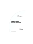
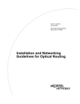
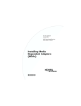
Part No. 212256-A
July 2001
4401 Great America Parkway
Santa Clara, CA 95054
Installing CWDM
Gigabit Interface
Converters
*212256-A*
Copyright © 2001 Nortel Networks
All rights reserved. July 2001.
The information in this document is subject to change without notice. The
statements, configurations, technical data, and recommendations in this document
are believed to be accurate and reliable, but are presented without express or
implied warranty. Users must take full responsibility for their applications of any
products specified in this document. The information in this document is
proprietary to Nortel Networks Inc.
Trademarks
Nortel Networks, the Nortel Networks logo, and the Globemark and are trademarks
of Nortel Networks.
Adobe and Acrobat Reader are trademarks of Adobe Systems Incorporated.
Statement of conditions
In the interest of improving internal design, operational function, and/or reliability,
Nortel Networks Inc. reserves the right to make changes to the products described
in this document without notice.
Nortel Networks Inc. does not assume any liability that may occur due to the use or
application of the product(s) or circuit layout(s) described herein.
EMI Compliance
Meets requirements of:
FCC Part 15, Subparts A and B, Class A
EN55022: 1998/CISPR22:1997), Class A
General License VDE 0871, Class B
(AmtsblVfg No. 243/1991, Vfg 46/1992) VCCI Class A ITE
EN55024:1998/CISPR24:1997
Caution: Use of controls or adjustments, or performance of procedures
other than those specified herein may result in hazardous radiation
exposure.
2
Caution: Only qualified technicians should install this equipment.
Place all printed circuit boards on an antistatic mat until you are ready to
install them. If you do not have an antistatic mat, wear a discharge leash
to free yourself of static before touching any of the printed circuit boards,
or free yourself of static by touching a grounded metal object before
handling a printed circuit board.
Product Safety
Meets requirements of:
CSA 22.2 No. 950-M95/UL1950, 3rd ed.
EN60950: 1992 /A1:1993 /A2:1993 /A3:1995 /A4:
199721CFR, Chapter I
EN60825-1:1994 /A11:1996
Warning: Fiber optic equipment can emit laser or infrared light that
can injure your eyes. Never look into an optical fiber or connector port.
Always assume that fiber optic cables are connected to a light source.
Vorsicht: Glasfaserkomponenten können Laserlicht bzw. Infrarotlicht
abstrahlen, wodurch Ihre Augen geschädigt werden können. Schauen
Sie niemals in einen Glasfaser-LWL oder ein Anschlußteil. Gehen Sie
stets davon aus, daß das Glasfaserkabel an eine Lichtquelle
angeschlossen ist.
Avertissement: L’équipement à fibre optique peut émettre des
rayons laser ou infrarouges qui risquent d’entraîner des lésions
oculaires. Ne jamais regarder dans le port d’un connecteur ou d’un
câble à fibre optique. Toujours supposer que les câbles à fibre optique
sont raccordés à une source lumineuse.
Advertencia: Los equipos de fibra óptica pueden emitir radiaciones
de láser o infrarrojas que pueden dañar los ojos. No mire nunca en el
interior de una fibra óptica ni de un puerto de conexión. Suponga
siempre que los cables de fibra óptica están conectados a una fuente
luminosa.
3
Avvertenza: Le apparecchiature a fibre ottiche emettono raggi laser o
infrarossi che possono risultare dannosi per gli occhi. Non guardare
mai direttamente le fibre ottiche o le porte di collegamento. Tenere in
considerazione il fatto che i cavi a fibre ottiche sono collegati a una
sorgente luminosa.
4
Introduction
This section describes how the Nortel Networks* coarse
wavelength division multiplexed Gigabit Interface Converter
(CWDM GBIC) works within the optical routing system. It also
provides a list of CWDM GBICs by wavelength and shows how
they are labeled and color-coded.
CWDM GBIC description
CWDM GBICs are transceivers that link Gigabit Ethernet ports
with fiber optic networks. WDM technology consolidates
multiple optical channels, using specific wavelengths to expand
available bandwidth, on a common optical fiber.
About the optical routing system
CWDM GBICs (Figure 1) are a component in the optical routing
system designed to support high speed data communication for
Metropolitan Area Networks (MANs). The system uses a grid of
eight CWDM optical wavelengths in both ring and point-to-point
configurations. All components are color-coded by wavelength
(Table 1 on page 7). The optical routing system also includes the
following:
•
Optical multiplexer-demultiplexer (CWDM OMUX)
•
Optical add/drop multiplexer (CWDM OADM)
For more information about the optical routing system, and
connecting CWDM GBICs to CWDM OMUXs and CWDM
OADMs, see Installation and Networking Guidelines for
Optical Routing, part number 212257-A.
5
Figure 1 CWDM GBIC
10292FA
CWDM GBIC labeling
Figure 2 shows how Nortel Networks CWDM GBICs are
labeled, including color-coding by wavelength.
Figure 2 Nortel Networks CWDM GBIC label
Model number
Bar code
Interface type
Fiber mode
Serial number
AA1419005
Wavelength
SFINA286V13
1000BASE-WDM GBIC
1470nm
Single Mode
Wavelength
color code
10396EA
6
Note: When
you contact Nortel Networks about this
product, have the following information available:
• Nortel Networks serial number
• Wavelength
• Interface type
• CWDM GBIC part number
CWDM GBIC model numbers
Table 1 lists the CWDM GBIC model numbers by wavelength
and matching multiplexers in the CWDM optical routing system.
The system uses color matching for simplifying connections
between the CWDM GBIC and the multiplexer.
Table 1 CWDM GBIC model numbers
Wavelength
(nm)/
color code
Model number
1470 /Gray
AA1419005
AA1402002
1490 /Violet
AA1419006
AA1402003
1510 /Blue
AA1419007
AA1402004
1530 /Green
AA1419008
AA1402005
1550 /Yellow
AA1419009
AA1402006
1570 /Orange
AA14190010
AA1402007
1590 /Red
AA14190011
AA1402008
1610 /Brown
AA14190012 AA14020011 AA1402009
CWDM
GBIC
CWDM
OADM
7
CWDM
OMUX-4
CWDM
OMUX-8
AA1402010
AA1402009
AA1402009
AA1402009
Handling, safety, and environmental
guidelines
Before installing a CWDM GBIC, read the following handling,
safety, and environmental guidelines:
•
CWDM GBICs are static sensitive. To prevent damage from
electrostatic discharge (ESD), follow your normal board
and component handling procedures.
•
CWDM GBICs are dust sensitive. When you store a CWDM
GBIC, or when you disconnect it from a fiber optic cable,
always keep the dust cover over the CWDM GBIC’s optical
bores.
•
To clean contaminants from the optical bores of a CWDM
GBIC, use an alcohol swab or equivalent to clean the ferrules
of the optical connector. This also helps to prevent damage to
the ferrules during handling.
•
Dispose of this product according to all national laws and
regulations.
Warning: Fiber optic equipment can emit laser or infrared
light that can injure your eyes. Never look into an
optical fiber or connector port. Always assume that fiber
optic cables are connected to a light source.
Installing a CWDM GBIC
Use the following procedure to install a CWDM GBIC in a
switching module. This procedure requires an alcohol swab for
cleaning the ferrules of the optical connector to prevent damage
during handling and installation.
8
To install a CWDM GBIC in the switching module:
1
Remove the CWDM GBIC from its protective packaging.
2
Verify that the CWDM GBIC is the correct wavelength for
your network configuration (Table 1 on page 7).
3
Remove the dust cover from the CWDM GBIC’s optical
bores.
4
To prevent damage during handling, clean the ferrules of the
optical connector with an alcohol swab.
5
Grasp the CWDM GBIC between your thumb and forefinger.
6
Insert the CWDM GBIC into the slot on the front panel of the
Gigabit Ethernet switching module (Figure 3). A clicking
sound indicates it is properly seated.
Note: CWDM
GBICs are keyed to prevent improper
insertion. If the CWDM GBIC resists pressure, do not
force it. Remove it, turn it over, and reinsert it.
The CWDM GBIC is installed.
For instructions about connecting the CWDM GBIC to a
multiplexer, see Installation and Networking Guidelines for
Optical Routing, part number 212257-A.
For instructions about monitoring communication between
the CWDM GBIC and the switch, see the user’s guide for the
switch.
9
Figure 3 Inserting a CWDM GBIC into the switching module
9708FA
Removing a CWDM GBIC
Use the following procedure to remove a CWDM GBIC. When
storing a CWDM GBIC, place a dust cover over the fiber optic
bores .
Note: When
disposing of a CWDM GBIC, comply with
all national laws and regulations.
To remove a CWDM GBIC from the switching module:
1
Disconnect the fiber cable from the CWDM GBIC connector.
2
Grasp the extraction tabs (Figure 1) located on either side of
the CWDM GBIC between your thumb and forefinger.
3
Slide the CWDM GBIC out of the Gigabit Ethernet module
slot.
4
If the CWDM GBIC does not slide easily from the module
slot, use a gentle side-to-side rocking motion while firmly
pulling the CWDM GBIC from the slot.
10
CWDM GBIC specifications
Table 2 CWDM GBIC specifications
Item
Specification
Physical dimensions
0.39 X 1.18 X 2.56 inches
(1 X 3 X 6.5 cm)
Connectors
single mode fiber optic SC
Cabling
SMF, 9 µm
Data rate
Nominal
range
1.0625 to 1250 Mbaud
Average launch power
minimum
maximum
0 dBm
+4 dBm
Transmitter extinction ratio
minimum
7 dB
Average receive power
minimum
maximum
-24 dBm
-1 dBm
Power supply
maximum
3.15 to 5.5 V, 40 mA
Data format
8 B/10 B
o
Operating temperature range
Regulatory
o
0 C to 60 C
Class 1 devices per FDA/CDRH and
1EC8251 Laser Safety Regulations
11
Note: A
minimum attenuation of 5 dB must be present
between the transmitter and receiver. To avoid receiver
saturation, you must insert a minimum attenuation of 5
dB when:
• testing the GBIC in loopback mode
• using short runs of fiber with no intermediate
CWDM OADM or CWDM OMUX
To determine the expected signal loss for a CWDM
OADM, CWDM OMUX, or fiber length, see Installation
and Networking Guidelines for Optical Routing, part
number 212257-A.
Given a loss budget of 24 dB and assuming fiber loss of
.25 dB/km, up to 96 km reach is supported with no
intermediate CWDM OADM or CWDM OMUX.
Connecting to Nortel Networks online
This section describes products, services, and support systems
that can be accessed online.
Hard-copy technical manuals
You can print selected technical manuals and release notes free,
directly from the Internet. Go to the www.nortelnetworks.com/
documentation URL. Find the product for which you need
documentation. Then locate the specific category and model or
version for your hardware or software product. Use Adobe*
12
Acrobat Reader* to open the manuals and release notes, search
for the sections you need, and print them on most standard
printers. Go to Adobe Systems at the www.adobe.com URL to
download a free copy of the Adobe Acrobat Reader.
You can purchase selected documentation sets, CDs, and
technical publications through the Internet at the
www1.fatbrain.com/documentation/nortel/ URL.
How to get help
If you purchased a service contract for your Nortel Networks
product from a distributor or authorized reseller, contact the
technical support staff for that distributor or reseller for
assistance.
If you purchased a Nortel Networks service program, contact one
of the following Nortel Networks Technical Solutions Centers:
Technical Solutions Center
Telephone
Europe, Middle East, and Africa
(33) (4) 92-966-968
North America
(800) 4NORTEL or (800) 466-7835
Asia Pacific
(61) (2) 9927-8800
China
(800) 810-5000
13
An Express Routing Code (ERC) is available for many Nortel
Networks products and services. When you use an ERC, your
call is routed to a technical support person who specializes in
supporting that product or service. To locate an ERC for your
product or service, go to the www12.nortelnetworks.com/ URL
and click ERC at the bottom of the page.
14