1
English
SPEAKER SYSTEM
SX-LT55
Thank you for purchasing a JVC speaker.
Before you begin using it, please read the instructions
carefully to be sure you get the best possible performance.
If you have any questions, consult your JVC dealer.
INSTRUCTIONS
LVT0991-002A
[U, UP]
cover_SX-LT55{U_UP]f.p65
3
04.7.26, 3:56 PM
English
Contents
Warnings, Cautions and Others ............................................. 2
Preparation ............................................................................ 2
Connection ............................................................................. 3
Specifications ......................................................... Back cover
Warnings, Cautions and Others
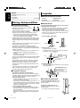
7 Precautions for installation
• To avoid personal injury or accidentally
dropping the unit, have two persons unpack,
carry, and install the unit.
• Do not install the speakers on an uneven
22.0 kg / 49.0 lb.
surface or in a place subject to vibration;
otherwise, they may fall over, causing damage or injury.
– Take the occurrence of earthquakes or other physical
shocks into consideration when selecting the installation
place, and secure the speakers thoroughly.
Preparation
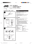
7 Checking the supplied accessories
• Feet (2)
• Screws (4)
• Speaker grille (1)
• Spacers (4)
If any item is missing, contact your dealer immediately.
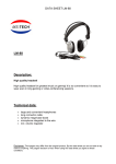
7 Attaching the feet
To prevent the speaker from falling over, be sure to attach
the supplied feet to the speaker.
• Take care not to drop the feet or speaker while assembling;
otherwise, it may cause damage to the floor or injury.
• Ensure enough space for assembly and installation.
• Place a large, thick cloth on the floor where you assemble the
speaker, so you can protect the floor and the speaker itself.
• Do not touch the speaker units.
1 Turn the speaker upside down.
• To prevent deformation or discoloration of the cabinet, do not
install the speakers where they are exposed to direct sunlight
or high humidity, and avoid installation near air conditioning
outlets.
• Speaker vibrations may cause howling. Place the speakers as
far away from the player as possible.
• The speakers are magnetically shielded to avoid color
distortions on TVs. However, if not installed properly, it may
cause color distortions. So, pay attention to the following when
installing the speakers.
– When placing the speakers near a TV set, turn off the TV’s
main power switch or unplug it before installing the
speakers.
Then wait at least 30 minutes before turning on the TV’s
main power switch again.
Some TVs may still be affected even though you have followed
the above. If this happens, move the speakers further away
from the TV.
• Tuner reception may become noisy or hissing if a speaker is
installed near the tuner. In this case, leave more distance
between the tuner and the speakers or use an outdoor
antenna for better tuner reception without interference from
the speakers.
• Do not lean against the speakers, as the speakers could fall
down or break, possibly causing an injury. Especially be
careful that children do not lean against them.
Speaker units
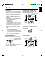
2 Attach the feet.
• Prepare a Phillips screw driver.
• Attaching the feet securely on the bottom of the speaker
with the four screws as illustrated.
Screw x 4
Foot
Speaker section
3 Install the speaker.
• Attach the supplied spacers under the feet if the speaker is
not installed stably.
Put multiple spacers in
piles under the feet if the
gap cannot be filled
enough by one spacer.
7 Precautions for daily use
• To maintain the appearance of the speakers
Wipe with a dry, soft cloth if the cabinet should become dirty.
If very dirty, apply a small amount of water or neutral detergent
to the cloth and wipe clean, then wipe with a dry cloth.
• To improve the sound field
– It is recommended to leave a space of more than 50 cm
between the speakers and the wall.
– If the speakers are facing a solid wall or glass door, etc., it is
recommended to furnish the wall with materials that absorb
sounds, for example by hanging up thick curtains, to prevent
reflections and standing waves.
• To use the speakers without any trouble
– Do not reproduce sounds at so high a volume that they are
distorted; otherwise, the speakers may be damaged by
internal heat buildup.
– When moving the speakers, do not pull the speaker cords;
otherwise, the speakers may fall over, causing damage or
injury.
Spacer
7 To remove the speaker grille
To remove the speaker grille, insert your
fingers at the bottom of the speaker grille,
then pull upward.
To attach the speaker grille, put the
projections of the speaker into the holes of
the speaker grille.
• Do not press the speaker grille strongly.
2
EN_SX-LT55[U_UP]f.p65
2
With the
foot-spacer side
facing up.
Foot
04.7.26, 3:56 PM
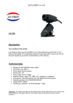
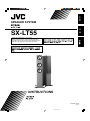
7 Connecting the speaker system to the amplifier
7 Conventional connection
Before connection—
• Turn off the power to the amplifier before connecting the
speaker system; otherwise, the speakers may be damaged.
1 Loosen the knobs of the “FULL RANGE” terminals.
2 Fit the speaker cords into the grooves of the “FULL
RANGE” terminals, then tighten the knobs to secure the
speaker cords and short-circuit plates.
• The impedance of the speaker is 6 Ω. Before connecting it to
your amplifier, check the speaker impedance range of your
amplifier. If the impedance of this speaker is out of the speaker
impedance range indicated on the amplifier, you cannot
connect this system to the amplifier.
• The maximum power handling capacity of the SX-LT55 is
150 W. Excessive input will result in abnormal noise and
possible damage.
English
Connection
FULL RANGE terminals
Short-circuit
plate
LOW FREQUENCY
(WOOFER ONLY)
LOW FREQUENCY
(WOOFER ONLY)
• Be sure to turn down the volume level to prevent unwanted
noise before performing following operations:
–
–
–
–
–
Turning on or off other components,
Operating the amplifier,
Tuning FM stations,
Fast-forwarding a tape,
Continuously reproducing high frequency oscillation or high
pitch electronic sounds.
• When using a microphone, do not aim it at the speakers or
use it near the speakers; otherwise, the howling which occurs
may damage the speakers.
KERS
SPEA
LEFT
T
RIGH
Speaker cord
(not supplied)
7 Bi-wiring connection
• Before replacing the cartridge, always turn off the power to the
turntable; otherwise, the clicking noise may damage the
speakers.
This speaker is bi-wireable. Comparing with the conventional
connection, the bi-wiring connection makes the sound field
larger, deeper, and richer.
• Use speaker cords as follows;
1 Loosen all speaker terminal knobs and detach the
short-circuit plates.
– Buy thick speaker cords rather than thin cords, and make
them as short as possible for connection.
– Use speaker cords of the same length for both left and right
speakers.
– Do not use long speaker cords; otherwise, the sound quality
may deteriorate.
– Using a special speaker cord such as a litz wire, a coaxial
cable, or a cord which has the specified connecting
directionality may influence the sound quality.
7 Connecting the speaker cord
Short-circuit plates
2 Connect the “FULL RANGE” terminals and “LOW
FREQUENCY” terminals separately to the speaker
terminals of the amplifier.
Connect the “INPUT” terminal of the speaker to the speaker
terminal of the amplifier.
(Red)
(Black)
Rotate the speaker terminal
knob counterclockwise and fit
the speaker cord into the
groove. Then rotate the knob
clockwise to secure the cord.
FULL RANGE
terminals
LOW FREQUENCY
terminals
HIGH FREQUENCY
HIGH FREQUENCY
LOW FREQUENCY
LOW FREQUENCY
(WOOFER ONLY)
(WOOFER ONLY)
KERS
(Red)
SPEA
LEFT
T
RIGH
• Make sure to match the polarity (ª and ·); otherwise, the
surround effect will become less effective.
Speaker cord
(not supplied)
3
EN_SX-LT55[U_UP]f.p65
3
04.7.26, 3:56 PM
Specifications
Type:
13.5 cm cone x 1
13.5 cm cone x 2
1.9 cm dome x 1
150 W
6Ω
100 Hz, 4 000 Hz
32 Hz to 80 000 Hz
89.5 dB/W•m
300 mm x 1 029 mm x 345 mm
(without feet:
180 mm x 1 000 mm x 326 mm )
22.0 kg
SPEAKER SYSTEM
Mass:
SX-LT55
Speaker unit
Woofer:
Mid and low range:
Tweeter:
Power handling Capacity:
Impedance:
Crossover frequency:
Frequency range:
Sound pressure level:
Dimensions (W x H x D):
3-way 4-speaker bass-reflex type
Magnetically-shielded type
Design and specifications subject to change without notice.
EN, CS, KO
© 2004 Victor Company of Japan, Limited
cover_SX-LT55{U_UP]f.p65
2
0704NSMMDWHCE
04.7.27, 3:42 PM
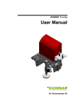
Unpacking the speaker /
/
SX-LT55
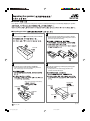
7 CAUTION /
/
This speaker is heavy, so that have two persons unpack to avoid personal injury or accidentally dropping the speaker.
7 Unpacking procedure /
/
1
3
Open the top (with
mark printed) of the carton box.
FRONT
Turn the package upside down, then pull it upward.
• When turning the package, hold packing pad in order to
prevent the speaker from falling.
FRONT
FRONT
Front side
Front side
2
4
Take out the inner carton and the cardboards.
• For the attachment of the feet and speaker grille in the
box, refer to page 2 of the Instructions.
Take out the speaker by removing the packing pad
on the both sides.
• Do not push the front side strongly; otherwise, the
speaker unit will be damaged.
Inner carton (contains accessories)
Packing pad
Cardboard
Cardboard
Cardboard
Cardboard
Front side
LV43379-002A
[U, UP]
EN, CS, KO
SX-LT55_caution_f.p65
1
04.7.26, 4:08 PM