1
ENGLISH
E-II-YDDN-0907
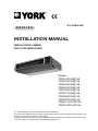
INSTALLATION MANUAL
DIGITAL SCROLL SERIES
DUCT TYPE INDOOR UNIT
Models:
YDDN-22C(A/B)15A
YDDN-28C(A/B)15A
YDDN-36C(A/B)15A
YDDN-45C(A/B)15A
YDDN-56C(A/B)15A
YDDN-71C(A/B)15A
YDDN-80C(A/B)15A
YDDN-90C(A/B)15A
YDDN-112C(A/B)15A
YDDN-140C(A/B)15A
For correct installation, read this manual before starting installation.
Only trained and qualified service personnel should install, repair or service air conditioning equipment. Users
should not install the air conditioner by themselves.
All pictures are only sketches. If there is any difference between pictures in this manual and the actual shape
of the air conditioner you purchased, the actual shape shall prevail.
' &
?@
8
8
1
8
8
%
)
+
*
>
*
=
&
)
13 +
8+
1+
3+
5+#
8
(A
1
(
3
!"
>0#
<
!8,899
8,899
=
B19<
;
$
#
<
()*+",-.
89
8
C ((((((
#
1#
3"
D
$%
#
A =
$
#
"
&
)
+
>
&'$%
B
56E69
"
&$ >
>
"
0" ! 8+
1+*
/ ! 8 1 / * +
A
@
)%
+
>
./
/=
FGBH
"
#
/
/&
<
(
/
=
) (+
./ 299
/646
;B
# )+
);+
# !A # #
5
;
#
Model(YDS)
A
B
C
D
E
F
G
H
I
J
K
L
M
N
22~36C(A/B)15A
45~80C(A/B)15A
90~140C(A/B)15A
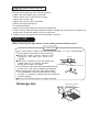
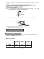
Duct Connection
The length of the duct should according to the static pressure outside the unit 39.2Pa
).
Panel installatio
(max. 98Pa
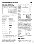
1. Unload the inner frame.
Slide the knob, release the
frame.
n
buckle from the outside frame hole, then unload the inner
Inside frame
Knob
Buckle
Outside frame
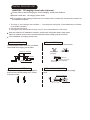
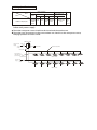
2. Hang the outside frame on the main body with face down. (4 places at 4 corners).
Hang the belt on the hook of the main body .
Note : The signal wire of the remote control receiver must be drawn out through the canvas
duct.
H ook
Main body
C anvas duct
Waist-s haped hole
fixed board
G allus
C eiling
O utside frame
O utside frame
3. Fix the outside frame and the canvas duct with screws.
Screw must be fixed from the bottom to the top.
Canvas duct
S crew
C eiling
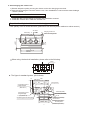
4. Hang up the outside frame until it sticks to the ceiling tightly.
Main body
Canvas duct
Duct
C eiling
O utside frame
5
P
5. Fix the main body and the outside frame with the x board of waist-shape hole (in two
places).
Tighten the other side of the board with screw to the outside frame.
Bend the top of the broken end.
Note : when hanging up the outside frame with the board of waist-shaped
belt, stick the outside frame tightly to the ceiling and it.
hole and the
H ook
Waist-s haped hole
xed board
O utside frame
6. Install the inner frame on the outside frame (the inverse sequence of unloading the inner
frame).
D uct
O utside frame
A ir i nlet
I nner frame
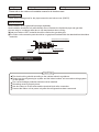
REFRIGERANT PIPE INSTALLATION
Allowed Length and Drop of Pipes
Requirements are
when installing the outdoor unit, please refer to the outdoor unit
installation manual for the detailed information.
SIZES OF THE PIPES
R22/R407C
R410A
R410A
19
12.7
15.9
Liquid
9.53
6.35
9.53
Models
All
22-36
45-140
Gas
6
/+
*!
3
)$597#+
4
>
A
>
A
>819%#
(
(
<
;
*
# *%'
,
*B
#
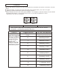
Wiring Specifications
Indoor Unit Power
Items
Manualr Switch
Power
Model
M
YDDN-22
~140C(A/B)15A
Controlling Wire
Power Cord
Indoor/Outdoor Unit
Signal Wire
Capacity Fuse Below 20m Below 50m Quantity
Single Phase
220-240V~
15A
15A
Twisted-pair Twisted-pair
2
2mm 2
4mm 2
Ground
Wire
Diameter
Not longer than 1500m
1.0mm 2
SingleWire
1.5mm
50Hz
Indoor unit power supply
The indoor unit power source should not be shared with the outdoor unit.
The indoor units that connect to the same outdoor unit should use the same power source,
creepage protector and main switch.
Outdoor Uni t
380V ~ 3N
Outdoor Power
Supply Creepag e Protec tion
Switch
Wire Dis tributionBox
Ground Wire
Ground Wire
Indoor/Outdoor
Signa l Wire (2-co re
scree ned wire)
Indoor Unit
220-240V~ 50Hz
Indoor P ower
Supply Creepag e Protec tion
Switch
Indoor Unit
10
#=
B
" ;B
8(8 8(1
81
$'
$'
(:
"#$
"#$
$'
$53(
:<5$((' ##<$55
@9(;@ @9(;@ @9(86@ )
84
+
&'#1
'/ B ; #
#)>+
9
1199<)92>+
8
1299<)89>+
1
3499<)81>+
3
5699<)86>+
5
6499<)19>+
6
7899<)16>+
4
2999<)39>+
7
:999<)31>+
2
88199<)59>+
:
85999<)69>+
11
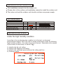
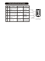
TROUBLESHOOTING
No.
Typ e
C ontents
L E D L amp flas h
R emarks
The e vaporator s ensor
R un lamp flashes
Malfun- check point is ab nomal , at 2.5Hz.
1 ction or ro om temp.se nsor is
After the malfunctions
disappear, it restores
automatically.
Malfun- Indoor/outdoor unit com2 ction munication is a bnormal.
Condenser sensor check
3 Malfun- point is abnormal or outdoor
ction temp. sensor is a bnormal.
After the malfunctions
disa ppea r, it res tores
automatically.
abnormal.
4 Malfun- Water level switch is
ction
5
Alarm
abnormal
Mode conflict
Th e timer la mp fla shes at 2. 5Hz.
Run lamp
All the indoor alarm After the malfunctions Timer lamp
lamps flash a t 0.5Hz. disappear, it restores
automatically.
If the malfunctions can t
Defrost lamp
Alarm lamp flashes be
s olved in three min.
all the indoor alarm
at 2.5Hz.
lamps flash at 0.5Hz.
Turn off the power to restore.
When the indoor unit turns
Defrost la mp
to heating mode or is turned
flashes a t 2.5Hz. off, the alarm will disappear.
12
Alarm lamp
Manual Switch
DE - COMMISSIONING DISMANTLING & DISPOSAL
This product contains refrigerant under pressure, rotating parts, and electrical connections which
may be a danger and cause injury!
All work must only be carried out by competent persons using suitable protective clothing and safety precautions.
Read the Manual
Risk of electric shock
Unit is remotely controlled
and may start without warning
1. Isolate all sources of electrical supply to the unit including any control system supplies switched by the unit. Ensure that all points of electrical and gas
isolation are secured in the OFF position. The supply cables and gas pipework may then be disconnected and removed. For points of connection refer
to unit installation instructions.
2. Remove all refrigerant from each system of the unit into a suitable container using a refrigerant reclaim or recovery unit. This refrigerant may then be
re-used, if appropriate, or returned to the manufacturer for disposal.Under No circumstances should refrigerant be vented to atmosphere. Where
appropriate, drain the refrigerant oil from each system into a suitable container and dispose of according to local laws and regulations governing
disposal of oily wastes.
3. Packaged unit can generally be removed in one piece after disconnection as above. Any fixing down bolts should be removed and then unit lifted from
position using the points provided and equipment of adequate lifting capacity. Reference MUST be made to the unit installation instructions for unit
weight and correct methods of lifting. Note that any residual or spilt refrigerant oil should be mopped up and disposed of as described above.
4. After removal from position the unit parts may be disposed of according to local laws and regulations.
E-II-YDDN-0907
ENGLISH