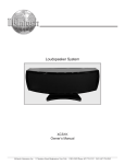
1
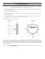
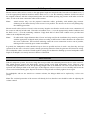
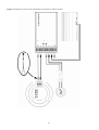
Installation Manual for
Profi Line Component System
CS 230 Profi
2-Way Component System
150 Watt
Part-No. 231496
CS 265 Profi
2-Way Component System
180 Watt
Part-No. 231497
CS 265 Profi Phase Plug
2-Way Component System
180 Watt
Part-No. 231111
CS 265 Profi Kick
2-Way Component System
180 Watt
Part-No. 231489
CS 365 Profi
3-Way Component System
180 Watt
Part-No. 231498
CS 365 Profi Kick
3-Way Component System
180 Watt
Part-No. 231490
Please read installation manual carefully before beginning installation!
RAC GmbH & Co. KG - P.O. Box 12 25 - 74899 Bad Rappenau - Germany
Telephone +49-7066 / 9006 0 - Telefax +49-7066 / 9006 50
http://www.rainbow-audio.de
Contents
Important Operational Information
User Safety Notice
Contents and Detail of Parts (CS 2xx)
Technical Data (CS 2xx)
Contents and Detail of Parts (CS 3xx)
Technical Data (CS 3xx)
Profi Line Capabilities
Positioning the Loudspeaker
Installing and Attaching the Woofer
Installing and Attaching the Midrange
Installing and Attaching the Tweeter
Cable Preparation
The Crossover
Connecting the Crossover (CS 2xx)
Connecting the Crossover (CS 3xx)
Philosophy of the Crossover
Attaching the Crossover
3
3
4
5
6
7
8
8
10
11
11
12
12
13
13
14
14
15
16
17
19
20
20
20
Figure 1
Figure 2
Figure 3
Figure 4
Figure 5
Figure 6
Figure 7
Dear valued customer,
We congratulate you on your purchase of our superior product and thank you for placing your trust in Rainbow®.
We have put together this installation manual with great consideration of different mechanical and acoustical auto
features. Nevertheless, mistakes can happen. We would greatly appreciate your bringing any mistakes you come
across to our attention.
Please review the list at hand (pages 4 and 6) of the complete system components to ensure against missing or
damaged equipment and notify your dealer immediately of any problems. Your dealer will provide you with any
necessary replacement parts and assistance you may require.
Best wishes,
Your Rainbow Team
2
Attention: Important Operational Information. Please Read Before Installation.
•
•
•
•
•
•
•
•
The loudspeaker may be operated only with the system-synchronized crossover and under observance of the
specified rated output power.
Interchanging the woofer and tweeter connections will lead to immediate destruction of the tweeter.
Beginning operation without the crossover, for example with an active crossover or non-system crossover, will
result in damage to the loudspeaker.
The tweeter is intended for active operation without passive crossover. Disregarding this will thermically
damage the tweeter by feeding it at too-high power levels.
When connecting the loudspeaker, crossover, and amplifier it is absolutely necessary to employ the same
polarity. Interchanging the polarity produces an unnatural sound lacking bass reproduction.
The component systems are acoustically synchronized as one unit. Supplementation through an auxiliary
loudspeaker or tradeout with a larger woofer is not possible as this would change the overall frequency
response or impedance of the system. An overload of the crossover or a single loudspeaker would then be
unavoidable.
The opening of the crossover for the purpose of altering the parts or function, for example bi-amping, is
considered foreign interference and grounds for termination of the warranty
For the purpose of technical safety, the loudspeaker should only be attached with the included self-tapping
screws. We accept no liablity for use of alternative methods of attachment.
User Safety Notice
Prevention of Damage from Accidents and Fire.
Our products are intended for use only by those possessing the necessary specialized knowledge. The relevant
safety regulations regarding related auto parts, the regulations on internal vehicle safety STVZO- TÜV, as well as
the regulations of the authorized vehicle manufacturers should be followed diligently.
3
Contents and Detail of Parts
CS 230 / CS 265
Fastening for Woofer:
2 pieces
2 pieces
2 pieces
8 pieces
8 pieces
8 pieces
grill 130 / 165 mm ∅ metal, black with rainbow logo
woofer 130 / 165 mm ∅ (screw terminal)
installation ring 130 / 165 mm ∅
self-tapping screw
3,9 x 32 DIN 7981 black
washer
M4 DIN black
self-tapping nut
3,9 DIN galvanised
A
B
C
G
H
I
Fastening for Tweeter:
2 pieces
2 pieces
2 pieces
2 pieces
2 pieces
CAL 26 Silk VOF, silk dome tweeter with neodymium motor (cable connection)
clamping ring (with 3 slugs)
threaded bolt
M4 to M5
washer
M5 DIN
hexagonal nut
M5 DIN
J
M
Q
U
V
Fastening for Crossover:
2 pieces
8 pieces
crossover (Highpass-/Lowpass)
self-tapping screw
3,9 x 13 DIN 7981 black
Miscellaneous:
8 pieces
8 pieces
terminal plug black, gold-plated for 2,5 mm² cable
terminal plug red, gold-plated for 2,5 mm² cable
1 piece
Allen wrench
1 piece
1 piece
installation manual
warranty card
4
X
Z
Technical Data
System
CS 230 Profi
CS 265 Profi
Peak power handling
Power rating
Sensitivity
Frequency response
Impedance
Crossover
Slope
Crossover frequency
Highpass adaption
Thermal protection
150 W
100 W
90 dB 1W/1m
48 - 25.000 Hz
4Ω
2-Way-Mono
2 x 18 dB / Octave
2.400 Hz
Linear gradient
HALO / PTC / Wire jumper (optional)
180 W
120 W
90 dB 1W/1m
39 - 25.000 Hz
4Ω
2-Way-Mono
2 x 18 dB / Octave
2.400 Hz
Linear gradient
HALO / PTC / Wire jumper (optional)
Woofer
Mounting depth without / with ring
External diameter without / with ring
Installation diameter
Fastening diameter
W 130 Profi
59 / 54 mm
137 / 156 mm
120 mm
128 mm
W 165 Profi
66 / 64 mm
167 / 190 mm
148 mm
156 mm
Tweeter
Mounting depth
External diameter
Fastening diameter
CAL 26 Silk VOF
20 mm
51 mm
44 mm
CAL 26 Silk VOF
20 mm
51 mm
44 mm
System
CS 265 Profi Phase Plug
CS 265 Profi Kick
Peak power handling
Power rating
Sensitivity
Frequency response
Impedance
Crossover
Slope
Crossover frequency
Highpass adaption
Thermal protection
180 W
120 W
90 dB 1W/1m
39 - 25.000 Hz
4Ω
2-Way-Mono
2 x 18 dB / Octave
2.400 Hz
Linear gradient
HALO / PTC / Wire jumper (optional)
180 W
120 W
90 dB 1W/1m
80 - 25.000 Hz
4Ω
2-Way-Mono
2 x 18 dB / Octave
2.400 Hz
Linear gradient
HALO / PTC / Wire jumper (optional)
Woofer
Mounting depth without / with ring
External diameter without / with ring
Installation diameter
Fastening diameter
W 165 Profi Phase Plug
66 / 64 mm
167 / 190 mm
148 mm
156 mm
W 165 Profi Kick
66 / 64 mm
167 / 190 mm
148 mm
156 mm
Tweeter
Mounting depth
External diameter
Fastening diameter
CAL 26 Silk VOF
20 mm
51 mm
44 mm
CAL 26 Silk VOF
20 mm
51 mm
44 mm
5
Contents and Detail of Parts
CS 365
Fastening for Midrange and Woofer:
2 pieces
2 pieces
2 pieces
2 pieces
2 pieces
2 pieces
16 pieces
16 pieces
16 pieces
grill 165 mm ∅ metal, black with rainbow logo
woofer 165 mm ∅ (screw terminal)
installation ring 165 mm ∅
grill 100 mm ∅ metall, black with rainbow logo
midrange 100 mm ∅ (screw terminal)
installation ring 100 mm ∅
self-tapping screw
3,9 x 32 DIN 7981 black
washer
M4 DIN black
self-tapping nut
3,9 DIN galvanised
A
B
C
D
E
F
G
H
I
Fastening forTweeter:
2 Pieces
2 Pieces
2 Pieces
2 Pieces
2 Pieces
CAL 26 Silk VOF, silk dome tweeter with neodymium motor (cable connection)
clamping ring (with 3 slugs)
threaded bolt
M4 to M5
washer
M5 DIN
hexagonal nut
M5 DIN
J
M
Q
U
V
Fastening for Crossover:
2 Pieces
2 Pieces
16 Pieces
crossover (Highpass-/Lowpass)
crossover (Midrange)
self-tapping screw
3,9 x 13 DIN 7981 black
Miscellaneous:
16 pieces
16 pieces
terminal plug black, gold-plated for 2,5 mm² cable
terminal plug red, gold-plated for 2,5 mm² cable
1 piece
Allen wrench
1 piece
1 piece
installation manual
warranty card
6
X
Y
Z
Technical Data
System
CS 365 Profi
CS 365 Profi Kick
Peak power handling
Power rating
Sensitivity
Frequency response
Impedance
Crossover
Slope
Crossover frequency
Highpass adaption
Thermal protection
180 W
120 W
90 dB 1W/1m
39 - 25.000 Hz
4Ω
3-way-Mono
3 x 18 dB / Octave
500 / 2.400 Hz
Linear gradient
HALO / PTC / Wire jumper (optional)
180 W
120 W
90 dB 1W/1m
80 - 25.000 Hz
4Ω
3-way-Mono
3 x 18 dB / Octave
500 / 2.400 Hz
Linear gradient
HALO / PTC / Wire jumper (optional)
Woofer
Mounting depth without / with ring
External diameter without / with ring
Installation diameter
Fastening diameter
W 165 Profi
66 / 64 mm
167 / 190 mm
148 mm
156 mm
W 165 Profi Kick
66 / 64 mm
167 / 190 mm
148 mm
156 mm
Midrange
Mounting depth without / with ring
External diameter without / with ring
Installation diameter
Fastening diameter
MR 100 Profi
48 / 44 mm
114 / 130 mm
95 mm
107 mm
MR 100 Profi
48 / 44 mm
114 / 130 mm
95 mm
107 mm
Tweeter
Mounting depth
External diameter
Fastening diameter
CAL 26 Silk VOF
20 mm
51 mm
44 mm
CAL 26 Silk VOF
20 mm
51 mm
44 mm
7
Profi Line Capabilities
Rainbow Profi Line loudspeakers are high-quality car audio systems that can be used with any commercial
amplifier. For optimal sound reproduction in the vehicle we recommend the use of a linear amplifier with at least
50 Watts of power. The excellent efficiency of the loudspeakers makes possible an enormous dynamic range,
which is fully appreciable even at the lowest performance levels.
Auto-specific tuning and the usage of select parts in the crossovers are characteristics that define our Profi Line.
Thermal protection as well as level adjustment within the high tone range are just as standard as the fundamental 12
dB or 18 dB coupling of the individual loudspeakers.
The 3-way component system is supplied with two separate LCR crossovers for the middle and high/low tone
ranges. This configuration was designed to take into consideration practical installation conditions and sound
purity.
Through this arrangement the individual range crossovers can be placed closer to the system being installed
without the danger of tonal influence by magnetic coupling of the energetic low and central tone ranges.
In order to ensure the system complements your vehicle interior, we offer you the option of specifying loudspeaker
covers to your desired color before installation.
Positioning the Loudspeaker
Rainbow loudspeakers may be installed in your vehicle in a variety of places. In determining the installation
location the following information should be considered:
Woofers require a large area for optimum sound reproduction. Car doors with a large air cushion between the door
lining and external metal or the rear windshield deck of an auto with a large trunk are ideal locations. In some
vehicles designated speaker locations in the instrument panel, doors, rear sides, and rear windshield deck offer the
necessary minimum area.
The installation location of the tweeter must, as with the woofer, fit freely into the available designated area or in a
newly chosen area, in order that an unencumbured radiation of sound is possible. Before installation, the
mechanical installation possibilities, with consideration given to acoustical expectations, should be reviewed. In
order to find the best placement for the tweeter to achieve optimal sound reproduction, installation should proceed
after installation of the woofer/midrange, as follows:
•
•
•
•
Attach tweeter, over the accompanying crossovers or over a suitable crossover, to the amplifier using long
cables in order to permit a free radius of action at the selected location.
Set the system into operation and insert appropriate CD. This selects the volume in such a way that the tweeter
is not overpowered by the mid- and low tone range.
Vary position of the tweeter until a vivid and spacious sound is achieved. At the same time, exchange the
polarity of the tweeter, (switch plus/negative connections at the connecting terminals) paying attention to
frontstaging and sound variations. Frontstaging adjusts itself only if the tweeter is not too far from the
midrange and/or woofer. The decision as to the optimal installation location requires patience and must be
accomplished by testing several varieties of music.
Mark the determined installation placement and prepare for assembly.
8
Important:
Rear and front windshields strongly reflect the tweeter signal and can make the sound seem shrill
and overpowering. Windshields can, for the purpose of support, be used if desired, however,
normally installation in the windshield proximity should be avoided. Upholstery absorbs high
frequency sounds, making sound reproduction seem flat and dull. Sufficient distance from head
rests, upholstered backrests, and seats is essential.
A fundamental consideration in selecting the installation location is that the individual system loudspeakers
should, for acoustical purposes, be kept as close as possible to one another. When the individual loudspeakers
are placed too far apart, an acoustical void that impairs the intended sound can result.
Important:
Review mechanical suitability before beginning installation into the selected location!
Built-in auto parts should not be removed. Take care with window mechanics and door handles
during door removal. Likewise, during rear area installations, use care around the gas tank. This
area should in no case be worked on in any way. In general, pay close attention to hidden cables
and lines, which should not be cut or removed. Self installation of the loudspeakers is possible,
however take note in advance of necessary specialized technical information about connections and
interior auto safety mechanics.
The most acoustically favorable installation location is not always mechanically suitable. In this case an
appropriate compromise between optimal sound reproduction and mechanical attachment should be determined.
Door Installation: In order to achieve optimal frontstaging, the tweeters should not be placed too deeply in the
door area. They should be installed, for instance, at shoulder height and as far forward as possible, in the vicinity
of the instrument panel. Suitable installation positions here are the side view mirror area and the upper door lining.
Placing the tweeters on diagonal spacer rings (about 20°) can be tonally advantageous, if thereby the arrangement
is done in such a way that the left tweeter radiates to the right door and/or right seat and the right tweeter radiates
sound toward the left door and/or the left seat. (In order to achieve optimal tweeter placement the scenario
described above should be followed.)
The midrange should be placed, whenever possible, between the tweeter and woofer, with preference being given
to proximity to the tweeters.
When possible, the woofers should be placed in the bottom area of the door lining. The distance between tweeters,
midrange, and woofers should be kept as small as possible, to prevent the sound of the loudspeakers from being
negatively impacted. (fig. 1). In order to achieve optimal woofer performance, i.e., kickbass, the total door space
must be used. That means that the splash guard on the doors must be cut in a u-shape in the woofer area and fixed
against resonating. In addition it must be made certain that the woofer is sealed to the door lining to avoid an
acoustical short-circuit. The door space should, in order to promote the flow of the sound waves, be loosely draped
with an absorbant material. A further measure helpful for optimization of sound is suppressing the resonance of the
door metals (on the door inside) with special absorbant mats. If the door lining has a tendency to resonate, a
wooden plate should be installed for further support. If this is not possible, foam material can be used to lessen the
effect. For installations in linings of 2-door vehicles the same procedures and considerations are recommended.
9
Rear Windshield Deck: The woofer should be arranged in direct proximity to the windshield. This installation
position prevents interior-specific difficulties in high-range sound reproduction. The tweeter and midrange should
be positioned as near as possible to the woofer. Additionally, attention should be paid that the tweeter is the
appropriate distance from the rear window and head rests. The rear window reflects and elevates sound, thereby
rendering high frequency sound reproduction shrill and overpowering. Head rests absorb high frequency sounds.
With rear windshield deck assembly, the use of angle mounts or tiltable housings is also recommended. A tilted
position allows sound to be reflected off the windshield directly toward the front seat, thereby rendering the sound
fuller and more voluminous. Connect the tweeter parts before cutting into the rear window deck and determine the
best position for optimal sound rendition by listening to music at a moderate volume. The tweeter and midrange
should be inserted thereafter to the extreme right or left (important for stereo location) in the rear window deck
(fig. 1).
Fig. 1: Positioning the Loudspeakers in Doors and Rear Window Deck.
10
Installing and Attaching the Woofer
CS 230 / CS 265 / CS 365
Note:
Do not attach via or puncture the membrane. Do not damage the membrane with a screwdriver or other
sharp tool.
•
After selecting the installation location, attach the installation ring (C) at the designated location, e.g. with
double-sided tape, and mark the necessary drill holes and the space for the woofer (inner circle of the
installation ring).
•
Carefully prepare the space for the woofer and drill 2.5 mm holes. Smooth all metal edges, drill holes carefully,
and remove any metal shavings or pieces. As needed, apply a protective varnish or edge protection.
•
Insert self-tapping nut 3.9 (I) into the drill holes.
•
Attach cables according to the instructions (pages 15 and 17) and appropriate polarity, and check the woofer
for accuracy of performance functions.
•
Insert woofer (B) into the installation ring (C) and attach woofer into drill holes in such a manner that the
connections always lie freely. Under no circumstances should these make contact with surrounding metal parts!
•
Carefully attach the woofer with the enclosed self-tapping screws 3.9x32 (G) and using the washers M4 (H).
Align woofer, ensuring it lies flat, adjust to prevent unevenness through the supporting rubber edge, and then
tighten screws. Make sure that the woofer lies completely flat and may not be turned by the screws.
•
Insert speaker cover (A), from above, perpendicularly into the installation ring (C), and firmly press.
Figure 2: Installing and Attaching the Woofers.
11
Installing and Attaching the Midrange
CS 365
In selecting the installation location, the position of the midrange in relation to the tweeter should be considered.
The loudspeakers should be placed as closely as possible to one another to achieve a complete sound effect.
Note:
Do not attach via or puncture the membrane. Do not damage the membrane with a screwdriver or other
sharp tool.
•
After selecting the installation location, attach the installation ring (F) at the designated location, e.g. with
double-sided tape, and mark the necessary drill holes and the space for the midrange (inner circle of the
installation ring).
•
Carefully prepare the space for the midrange and drill 2.5 mm holes. Smooth all metal edges and drill holes
carefully and remove any metal shavings or pieces. As needed, apply a protective varnish or edge protection.
•
Insert self-tapping nut 3.9 (I) into the drill holes.
•
Attach cables, according to the instructions (page 17) and appropriate polarity, and check the woofer for
accuracy of performance functions.
•
Insert midrange (E) into the installation ring (F) and attach midrange into drill holes in such a manner that the
connections always lie freely. Under no circumstances should these make contact with surrounding metal parts!
•
Carefully attach the midrange with the enclosed self-tapping screws 3.9x32 (G) and using the washers M4 (H).
Align midrange, ensuring it lies flat, adjust to prevent unevenness through the supporting rubber edge, and then
tighten screws. Make sure that the midrange lies completely flat and may not be turned by the screws.
•
Insert speaker cover (D), from above, perpendicularly into the installation ring (F), and firmly press.
Figure 3: Installing and Attaching the Midranges.
12
Installing and Attaching the Tweeter
CS 230 / CS 265 / CS 365
Installation Location: Door Installation (front/rear), rear installation, side view mirror area installation,
instrument panel installation, and rear windshield deck installation
•
Fix the installation template of the tweeters at the selected location with tape and, along the indicated line,
carefully cut and smooth edges.
•
Place tweeter (J) in the prepared opening.
•
Press the locking ring (M), from the rear, over the tweeter (J), and evenly tighten the 3 screws (P) with the
included Allen wrench.
•
Connect the tweeter with the crossover, according to the approprate polarity, and as described in the
instructions (page 15 and 17), and make necessary adjustments in level.
Figure 4: Installing and attaching the tweeters.
For an alternative attachment of the tweeter (e.g., with self-designed mounting plates) special threaded bolts (M4
on M5), washers (M5) and hexagonal nuts (M5) are included in the system. Screw the M4-side of the mounting
bolts to the tweeter. The appropriate bolt hole M4 is located in the magnetic base of the tweeters. Loosely tighten
the screw mountings with the wrench (SW7). Afterwards screw the tweeter onto the mount with the hexagonal nut
and using the washer.
Note:
Use only the enclosed threaded bolts for the alternative attachment method. Use of incorrect or too long
screws can damage the tweeters.
13
Cable Preparation
Shorten tweeter cable (at least 1 mm²) to the appropriate length and strip both ends. Insert the red conduit cover (+)
over the appropriately marked conductor and the black cover (-) over the remaining conductor. Solder one end of
the stripped conductor with the u-shaped metal jacket. Provide suitable polarity plug contacts at the other end of the
cable, as well as the short connection cables of the tweeters.
Note:
Attach tweeter only over the prepared connection cables, preferably with suitable plug contacts.
Soldering of the cables directly to the tweeter is not possible. The tweeter can be severely damaged by
the soldering procedure.
Shorten woofer cable (at least 2.5 mm²) to the necessary length to run from the woofer to the screw connections of
the crossover and strip at both ends. Insert the red conduit cover (+) over the appropriately marked conductor and
the black cover (-) over the remaining conductor. Equip both ends of cables with conduit covers provided and
solder to the u-shaped metal jacket.
Note:
If cables with a larger diameter than 2.5 mm² are being used for the installation, they must be provided
with the appropriate u-shaped metal jackets according to DIN 46244. Cables should not be soldered at
the screw connections. The heat from soldering causes the screw connections to move out of position,
making misfires caused by poor contact unavoidable.
In general, the loudspeaker cables should be kept as short as possible and run in such a way that they are kept
separate from the auto’s electrical system, thereby preventing distortion from the generator and electrical wiring.
The loudspeaker cables can also be twisted together to help prevent distortion. Rolling up excess loudspeaker cable
length is not helpful, as it merely increases chances of distortion.
The Crossovers
With all component systems, the tweeter range has been provided with a thermal protection device in the crossover.
This added measure protects the high-quality tweeter against overly high performance levels. However, with
extremely high performance levels, the protecting halogen bulb (12V/20W/G4) can burn out and must then be
replaced with a halogen bulb of the same type. If this happens, remove crossover covers carefully and loosen the
screws on the bulb mounting plate. Replace the defective halogen bulb and firmly tighten screws again.
For audiophiles who are not sensitive to extreme volumes, the halogen bulb can be replaced by a silver wire
jumper.
Note: The overload protection of the tweeter will thereby be lost, therefore care should be taken in adjusting the
volume control!
14
Connecting the Crossover
CS 230 / CS 265
The crossovers (X) and the loudspeakers (B) are provided with screw connections and different plug connections as
well as with polarity markings. Through this control system are the appropriate steps in connecting the
loudspeakers with the crossovers ensured. The number sequence 1 to 7 is specified at the crossover base
underneath the screw connections.
Firmly tighten the screws of the crossover and woofer connections!
Connection of Amplifier/Radio:
Attach prepared loudspeaker cable (2.5 mm²) at the screw connections „Input“ (6 and 7) of the crossover, whereby
the connector with the red conduit cover is connected with the positive terminal (7) and the connector with the
black conduit cover with the minus connection (6). Attach the other end of the loudspeaker cable making sure the
polarity corresponds with that on the amplifier and radio sides.
Connection of Woofer:
Attach prepared loudspeaker cable (2.5 mm²) at the screw connections „Woofer“ (1 and 2) of the crossover,
whereby the connector with the red conduit cover is connected with the positive terminal (1) and the connector
with the black conduit cover with the minus connection (2). Attach the other end of the loudspeaker cable, making
sure the polarity (+/-) of the connections corresponds, and connect to the woofers.
Connection of Tweeter:
Attach prepared loudspeaker cable (1 mm²) at the screw connections „Tweeter “ (3/4 and 5) of the crossover,
whereby the connector with the red conduit cover is connected with the positive terminal (3/4) and the connector
with the black conduit cover with the minus connection (5). Connect the other end of the loudspeaker cable,
preferably with suitable contacts and making sure the polarity of the connections correspond, to the available
connection cable of the tweeters (+ = black marking)
The component systems allow for the possibility to correct at the crossover the intensity of the acoustic pressure in
the tweeter range, in order to project a vivid and unobstrusive sound, depending upon location of the tweeters.
Position „+ lin.“ (3), Frequency Response:
For this, attach the positive terminal (+) of the tweeters to the screw connection „ lin.“ (3) of the crossover.
Recommended with installation of the tweeters outside of the direct listening axis, e.g. lower door installation, floor
space installation, rear installation next to head rests, or with heavily padded vehicle interiors with strong high
frequency sound absorbtion.
Position „+ ref.“ (4), Gradient Frequency Response:
For this, attach the positive terminal (+) of the tweeters to the screw connection „+ ref.“ (4) of the crossover.
Recommended with installation of the tweeters directly in the listening axis and/or ear proximity, e.g. A- or Bpillar, front instrument panel area with strong windshield reflection, rear installation in direct proximity of the
back window. The gradient frequency response was designed in such a way that the middle- to high-tone levels
drop continually by octave. Thus stress-free listening with excellent frontstaging is guaranteed.
If the woofer and tweeter are placed very closely together, the polarity of the tweeters as indicated at the crossover
(+ at 3/4 and - at 5) should be maintained. ⇒ Optimal tuning. In mechanical situations where the woofer and
tweeter are placed very far apart, it is recommended that the polarity of the tweeters be turned approximately 180°.
In addition, clamp the tweeter cable with red conduit cover sleeve from the positive terminal (3/4) of the crossover
and fasten on the minus connection (5). Afterwards take the tweeter cable with the black conduit sleeve from the
minus connection (5) and fasten to the positive terminal (3/4). A more enclosed sound can be achieved by this
measure.
15
Figure 5: Diagram of Connections and Cable Preparation of 2-Way Systems.
16
Connecting the Crossover
CS 365
The crossovers for the high/low range (X) as well as the middle range (Y) and the loudspeaker (B+E) are provided
with screw connections and different plug connections as well as with polarity markings. Through this control
system the appropriate steps in connecting the loudspeakers with the crossovers are ensured. The number sequence
1 to 7 is specified at the crossover base underneath the screw connections.
Firmly tighten the screws of the crossover, midrange, and woofer connections!
Connection of Amplifier/Radio:
Attach prepared loudspeaker cable (2.5 mm²) at the screw connections „Input Amplifier“ (6 and 7) of the middle
range crossover (Y), whereby the connection with the red conduit cover is connected with the positive terminal (1)
and the connection with the black conduit cover with the minus connection (2). Attach the other end of the
loudspeaker cable making sure the polarity corresponds with that on the amplifier and radio sides.
Connection of High/Low Crossovers:
Attach prepared loudspeaker cable (2.5 mm²) at the screw connections „Output Crossover“ (1 and 2) of the middle
range crossover (Y), whereby the connection with the red conduit cover is connected with the positive terminal (1)
and the connection with the black conduit cover with the minus connection (2). Attach the other end of the
loudspeaker cable on the screw connections „Input“ (6 and 7) of the High/Low crossovers (X), whereby the
connection with the red conduit cover (7) is connected with the positive terminal and the connection with the black
conduit cover (6) is connected with the negative terminal.
Connection of Woofer:
Attach prepared loudspeaker cable (2.5 mm²) at the screw connections „Woofer“ (1 and 2) of the high/low
crossover (X), whereby the connection with the red conduit cover is connected with the positive terminal (1) and
the connection with the black conduit cover with the minus connection (2). Attach the other end of the loudspeaker
cable, making sure the polarity (+/-) of the connections corresponds, and connect to the woofers.
Connection of Midrange:
Attach prepared loudspeaker cable (2.5 mm²) at the screw connections „Midrange“ (3/4 and 5) of the middle range
crossover (Y), whereby the connection with the red conduit cover is connected with the positive terminal (3/4) and
the connection with the black conduit cover with the minus terminal (5). Attach the other end of the loudspeaker
cable, making sure the polarity (+/-) of the connections corresponds, and connect to the woofers.
The component systems allow for the possibility to correct at the middle range crossover the intensity of the
acoustic pressure in the middle tone range, in order to project a vivid and unobstrusive sound, depending upon
location of the midranges.
Installation for Selection Field d:
Position „+3dB“ (4), Frequency Response:
For this, attach the positive terminal (+) of the midranges to the screw connection „+3dB“ (4) of the crossover.
Additionally, carefully remove the crossover cover and place the wire jumper on pin d „C“. Recommended with
installation of the midranges outside of the direct listening axis, e.g. lower door installation, floor space
installation, rear installation next to head rests, or with heavily padded vehicle interiors with strong middle range
frequency sound absorbtion.
Position „+0dB / A“ (3), Gradient Frequency Response from 3 to 6 dB:
For this, attach the positive terminal (+) of the midranges to the screw connection „+0dB“ (3) of the crossover.
Additionally, carefully remove the crossover cover and place the wire jumper on pin d „A“. Recommended with
installation of the midranges directly in the listening axis and/or ear proximity, e.g. side-view mirror area and
upper door installations. According to personal listening tastes, preference may be given to this position or
position „+0dB /B“.
17
Position „+0dB / B“ (3), Gradient Frequency Response from 4 to 8 dB:
For this, attach the positive terminal (+) of the midranges to the screw connection „+0dB“ (3) of the crossover.
Additionally, carefully remove the crossover cover and place the wire jumper on pin d „B“. Recommended with
installation of the midranges directly in the listening axis and/or ear proximity, e.g. A or B-pillar, front instrument
panel area with strong windshield reflection, rear installation in direct proximity of the back window.
Additional Installation for Selection Field c:
This installation is applicable for all above described installations of selection field dand generally lowers the
frequency level around 3 dB!
Position „A“, No Additional Frequency Response:
For this, carefully remove the crossover cover and place the wire jumper onto pin c „A“.
Position „B“, Additional Frequency Response from 3 dB:
For this, carefully remove the crossover cover and place the wire jumper onto pin c „B“.
Connection of the Tweeter:
Attach prepared loudspeaker cable (1 mm²) at the screw connections „Tweeter “ (3/4 and 5) of the woofer/tweeter
crossover (X), whereby the connection line with the red conduit cover is connected with the positive terminal (3/4)
and the connection with the black conduit cover with the minus connection (5). Connect the other end of the
loudspeaker cable, preferably with suitable contacts and making sure the polarity of the connections corresponds, to
the available connection cable of the tweeters (+ = black marking) .
The component systems allow for the possibility to correct at the crossover the intensity of the acoustic pressure in
the high tone range, in order to project a vivid and unobstrusive sound, depending upon location of the tweeters.
Position „+lin. / A“(3), Frequency Response:
For this, attach positive terminal (+) of the tweeters to the screw connection „+lin.“ (3) of the crossover.
Additionally, carefully remove the crossover cover and place the wire jumper on pin „A“. Recommended with
installation of the tweeters outside of the direct listening axis, e.g. lower door installation, floor space installation,
rear installation next to head rests, or with heavily padded vehicle interiors with strong high range frequency
sound absorbtion.
Position „+ lin. / B“ (3), Gradient Frequency Response from 3 dB:
For this, attach the positive terminal (+) of the tweeters to the screw connection „+lin.“ (3) of the crossover.
Additionally, carefully remove the crossover cover and place the wire jumper on pin „B“. Recommended with
installation of the tweeters directly in the listening axis and/or ear proximity, e.g. side-view mirror area and upper
door installations. According to personal listening tastes, preference may be given to this position or position
„+ref“.
Position „+ ref.“ (4), Gradient Frequency Response:
For this, attach the positive terminal (+) of the tweeters to the screw connection „+ ref.“ (4) of the crossover.
Additionally, carefully remove the crossover cover and place the wire jumper on pin „B“. Recommended with
installation of the tweeters directly in the listening axis and/or ear proximity, e.g. A or B-pillar, front instrument
panel area with strong windshield reflection, rear installation in direct proximity to the back window. The gradient
frequency response was designed in such a way that the middle- to high-tone levels drop continually by octave.
Thus stress-free listening with excellent frontstaging is guaranteed.
If the woofer, midrange, and tweeter are placed very closely together, the polarity of the tweeters as indicated at the
crossover (+ at 3/4 and – at 5 ) should be maintained. ⇒ Optimal tuning. In mechanical situations where the
midrange and tweeter are placed very far apart, it is recommended that the polarity of the tweeters be turned
approximately 180°. In addition, clamp the tweeter cable with red conduit cover sleeve from the positive terminal
(3/4) of the tweeter/woofer crossover (X) and fasten on the minus connection (5). Afterwards take the tweeter cable
with the black conduit sleeve from the minus connection (5) and fasten to the positive terminal (3/4). A more
enclosed sound can be achieved by this measure.
18
Figure 6: Diagram of Connection of the 3-Way System and Cable Preparation.
19
Philosophy of the Crossover
Experimentation is highly encouraged!
The crossovers are designed in such a way that a multitude of sound combinations is possible, allowing listeners to
select their personal preference. Because each person hears differently and each vehicle possesses different
acoustics, we can give only basic positioning recommendations here. Therefore, experimentation incorporating
individual preferences is encouraged! Normally high and middle range tones sound louder on the driver side, since
the driver sits directly in the sound field of the loudspeakers. The front passenger side is comparatively quieter,
since the speakers are located farther away, with timing delays even being detectable. The result is inevitably an
unbalanced sound.
A basic correction of the sound can be achieved as follows: The crossovers of the front passenger side can be
adjusted through „Frequency Response“. However, the frequency of the crossovers on the driver's side is adjusted
until a pleasant, stress-free sound is achieved. Under normal conditions thereafter, high and middle range tones are
around at least 6 dB quieter than on the front passenger side. For optimal positioning, a professional dealer, who
can more accurately position the frequency response using specific measuring instruments, should be contacted.
Note:
It is important that all loudspeakers are correctly attached before start-up of the crossovers. If the
crossovers are set into operation without the loudspeakers being hooked up, a very high current is
produced on the unloaded LC-filters, which can, under the circumstances, destroy the coils! The wire
jumpers of the crossovers must always be placed on the specified pins, according to the instructions
above. Other combinations are not functional and do not behave like unattached loudspeakers! What’s
more, inproper connection of the crossover will prevent it from working within the intended range.
Attachment of the Crossover
Fasten crossovers (X and/or Y) to a suitable, easily accessible, and well-ventilated location in the vehicle with the
accompanying self-tapping screws 3,9x13 (Z) or double-sided tape.
Note:
Do not attach crossovers with sink screws! When using sink screws the mounting feet can be destroyed.
During the placement of the crossovers maintain a large distance from cable harnesses, in order to avoid
inductive distortion. If inductive distortion occurs, immediately change the position of the crossovers.
Figure 7: Attachment of the Crossover.
Version: MPJ-JS/6.2 - 09/04
This document is protected by copyright. All duplications, and/or reproductions, in full or part, as well as all renditions of the
illustrations, with or without alterations, are permitted only with written agreement from RAC GmbH & Co. KG.
Copyright © 2004 by RAC GmbH & Co. KG. Rainbow® is a registered trademark.
20