1
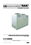
MasterCase 2
User manual
We wish to save you time and money!
We can assure you that the thorough reading of this manual will guarantee correct installation
and safe use of the product described.
IMPORTANT WARNINGS
BEFORE INSTALLING OR HANDLING THE DEVICE PLEASE CAREFULLY READ AND FOLLOW THE INSTRUCTIONS DESCRIBED IN THIS MANUAL.
This device has been manufactured to operate risk-free for its specific purpose, as long as:
it is installed, operated and maintained according to the instructions contained in this manual;
the environmental conditions and the voltage of the power supply correspond to those specified.
All other uses and modifications made to the device that are not authorised by the manufacturer are considered incorrect.
Liability for injury or damage caused by the incorrect use of the device lies exclusively with the user.
Please note that this unit contains powered electrical devices and therefore all service and maintenance operations must be performed by specialist and qualified
personnel who are aware of the necessary precautions.
Disconnect the machine from the mains power supply before accessing any internal parts.
INFORMATION FOR USERS ON THE CORRECT HANDLING OF WASTE ELECTRICAL AND ELECTRONIC EQUIPMENT (WEEE)
In reference to European Union directive 2002/96/EC issued on 27 January 2003 and the related national legislation, please note that:
1. WEEE cannot be disposed of as municipal waste and such waste must be collected and disposed of separately;
2. The public or private waste collection systems defined by local legislation must be used. In addition, the equipment can be returned to the distributor at the end of
its working life when buying new equipment.
3. The equipment may contain hazardous substances: the improper use or incorrect disposal of such may have negative effects on human health and on the
environment;
4. The symbol (crossed-out wheeled bin) shown on the product or on the packaging and on the instruction sheet indicates that the equipment has been introduced
onto the market after 13 August 2005 and that it must be disposed of separately;
5. In the event of illegal disposal of electrical and electronic waste, the penalties are specified by local waste disposal legislation.
CONTENTS
1.
User interface.........................................................................................................................................................................................................7
1.1
Functions of the Buttons and LEDs on the PST small terminal.............................................................................................................................. 7
1.2
Functions of the Buttons and LEDs on the PGD0 terminal .................................................................................................................................... 8
2.
Setting the parameters...........................................................................................................................................................................................9
2.1
Accessing the parameters from the PGD0 display ............................................................................................................................................... 9
2.2
Accessing the parameters from the PST display ................................................................................................................................................ 10
3.
Digital input configuration ..................................................................................................................................................................................... 11
3.1
General operating principle................................................................................................................................................................................. 11
4.
Analogue input configuration ................................................................................................................................................................................ 12
4.1
General operating principle................................................................................................................................................................................. 12
4.2
Types of probes.................................................................................................................................................................................................. 12
4.3
Calibration and offset ......................................................................................................................................................................................... 12
4.4
Control probes.................................................................................................................................................................................................... 12
4.5
Virtual probe....................................................................................................................................................................................................... 12
5.
Digital output configuration ................................................................................................................................................................................... 13
5.1
General operating principle................................................................................................................................................................................. 13
6.
Other settings....................................................................................................................................................................................................... 13
6.1
H parameters ..................................................................................................................................................................................................... 13
7.
Temperature control ............................................................................................................................................................................................. 14
7.1
General operating principle................................................................................................................................................................................. 14
7.2
Safety parameters and control activation times................................................................................................................................................. 14
7.3
Continuous cycle function .................................................................................................................................................................................. 16
7.4
“Duty cycle setting” function (safety control)..................................................................................................................................................... 16
7.5
Temperature monitoring..................................................................................................................................................................................... 16
8.
Night-time operation............................................................................................................................................................................................. 17
8.1
General operating principle................................................................................................................................................................................. 17
9.
Fans ..................................................................................................................................................................................................................... 18
9.1
General operating principle................................................................................................................................................................................. 18
9.2
Normal operation................................................................................................................................................................................................ 18
9.3
Defrost, dripping, post-dripping .......................................................................................................................................................................... 19
10.
Defrost.......................................................................................................................................................................................................... 20
10.1
General operating principle........................................................................................................................................................................... 20
10.2
Structure of the defrost function .................................................................................................................................................................. 20
10.3
“Actual” defrost............................................................................................................................................................................................ 21
10.4
Dripping and post-dripping times.................................................................................................................................................................. 21
10.5
Cyclical defrost ............................................................................................................................................................................................. 21
10.6
Defrost on start-up ....................................................................................................................................................................................... 21
10.7
Network defrost ........................................................................................................................................................................................... 21
10.8
Management of the second evaporator ....................................................................................................................................................... 22
10.9
Skip defrost .................................................................................................................................................................................................. 22
10.10
HI alarm bypass after defrost ....................................................................................................................................................................... 22
10.11
Priority of defrost over safety times and the activation of the controller ...................................................................................................... 22
10.12
Management of the user interface during defrost ........................................................................................................................................ 22
11.
11.1
11.2
Electronic valve............................................................................................................................................................................................. 23
General operation ......................................................................................................................................................................................... 23
Configuration of the system parameters ...................................................................................................................................................... 23
12.
12.1
12.2
12.3
HACCP.......................................................................................................................................................................................................... 24
General operation ......................................................................................................................................................................................... 24
HA alarm ...................................................................................................................................................................................................... 24
HF alarm ....................................................................................................................................................................................................... 24
13.
13.1
13.2
13.3
13.4
13.5
13.6
13.7
Network functions......................................................................................................................................................................................... 25
Local network operation (pLAN)................................................................................................................................................................... 25
pLAN network configuration......................................................................................................................................................................... 25
Downloading the parameters ....................................................................................................................................................................... 26
Failed download signal ................................................................................................................................................................................. 26
Network defrost in multiplexed systems ...................................................................................................................................................... 26
Remote alarm signals................................................................................................................................................................................... 26
Supervisory network..................................................................................................................................................................................... 27
14.
14.1
14.2
Alarms .......................................................................................................................................................................................................... 28
Summary table ............................................................................................................................................................................................. 28
Notes and descriptions................................................................................................................................................................................. 29
15.
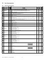
List of parameters ......................................................................................................................................................................................... 31
15.1
(Prb) Probe parameters ................................................................................................................................................................................ 31
15.2
(rEG) Control parameters.............................................................................................................................................................................. 32
15.3
(cMP) Safety time and control activation parameters .................................................................................................................................. 32
15.4
(dEF) Defrost management parameters ....................................................................................................................................................... 33
15.5
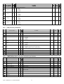
(ALr) Alarm parameters................................................................................................................................................................................ 33
15.6
(FAn) Evaporator fan management parameters............................................................................................................................................ 34
15.7
(CnF) Configuration parameters.................................................................................................................................................................... 34
15.8
(SEt) Set point parameters........................................................................................................................................................................... 34
15.9
(HcP) HACCP parameters ............................................................................................................................................................................. 35
15.10
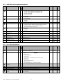
(rtc) RTC parameters (Real Time Clock) ....................................................................................................................................................... 35
15.11
(EEv) Valve parameters ................................................................................................................................................................................ 36
15.12
Outputs (PGD only) ....................................................................................................................................................................................... 37
15.13
Service (PGD only)........................................................................................................................................................................................ 37
15.14
Initialisation (PGD only)................................................................................................................................................................................. 37
15.15
Unit ON/OFF (PGD only)................................................................................................................................................................................ 37
15.16
Network (PGD only)...................................................................................................................................................................................... 38
1. User interface
The MasterCase2 uses the PGD0 display and the series of standard PST terminals as the user interface.
This terminals, as well as being the same used by other Carel instruments (consequently allowing a reduction in product codes), offer various solutions:
•
PGD0 terminal with 6 buttons;
•
PST small terminal with 3 digits and 3 buttons;
•
simple remote display with 3 digits.
Important: The use of the PGD terminal excludes the use of any PST terminals.
If the PST terminal is left connected, the display is not updated, remaining on the last value displayed.
Each button is backlit by a LED to signal the status of the unit (outputs active, alarms, etc...).
The terminals are not required for the operation of the MasterCase2, but rather are used to program the controller.
The terminals can be connected “live”, that is, when the instrument is on, without creating problems in operation.
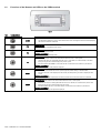
1.1
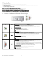
Functions of the Buttons and LEDs on the PST small terminal
Fig. 1
Button
Function
UP
Description
Normal operation
•
Pressed for more than one second activates or deactivates the light relay;
•
Pressed together with SET displays the value of the third probe (S3);
•
Pressed together with DOWN for 5 seconds activates or deactivates the continuous cycle function.
Parameter programming
•
Moves from one parameter to the previous;
•
Increases the value of the selected parameter;
•
Pressed together with SET returns to the menu list.
LED
•
DOWN
SET
Code +03P220221 rel. 1.0 dated 28/10/05
Steady: controller on;
Normal operation
•
Pressed for 5 seconds starts a local manual defrost, if the conditions allow;
•
Pressed for 5 seconds together with SET starts a network manual defrost, if the conditions allow;
•
Pressed together with UP for 5 seconds activates or deactivates the continuous cycle function;
•
Pressed together with SET displays the value read by the defrost probe (S2);
Parameter programming
•
Moves from one parameter to the next;
•
Decreased the value of the selected parameter.
LED
•
Steady: defrost active
Normal operation
•
Silences the audible alarm (buzzer) and deactivates the alarm relay, if active;
•
Pressed for 5 seconds together with DOWN starts a network manual defrost, if the conditions allow;
•
Pressed for 5 seconds displays the control set point;
•
Pressed for more than 6 seconds. When no alarms are active, accesses the type F parameters; entering
the password PP (22) accesses all the parameters, divided into groups, that can be selected and modified.
•
Pressed together with UP displays the value read by the third probe (S3);
•
Pressed together with DOWN displays the value read by the defrost probe (S2);
Parameter programming
•
Displays the value of the selected parameter or exits programming mode;
•
Pressed together with UP returns to the menu list.
LED
•
Steady: alarm active.
7
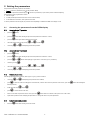
1.2
Functions of the Buttons and LEDs on the PGD0 terminal
Fig. 2
1.2.1
Terminal buttons
Button
Function
•
ALARM
PRG
ESC
UP
ENTER
DOWN
Code +03P220221 rel. 1.0 dated 28/10/05
•
Description
Displays any alarms present and deactivates the alarm relay, if active.
The LED flashing indicates a previous alarm that has been reset. Pressing the button momentarily displays
the alarm and switches off the LED.
Normal operation
•
Accesses the programming menu screens.
Normal operation
•
Returns to the main screen.
Parameter programming
•
Returns to the programming menu.
Normal operation
•
Scrolls the previous screens in the same branch when the cursor is in the top left;
•
Increases the value of a setting field when the cursor is in the field; for a selection field, on the other
hand, pressing the arrow button displays the previous option
•
Pressed together with DOWN for 5 seconds activates or deactivates the continuous cycle function.
Parameter programming
•
Increases the value of the parameter displayed.
Normal operation
•
Moves the cursor between the “home” position (top left) and the setting or selection fields;
•
Pressed in the main screen displays the value read by the main probes, press ESC to display the main
screen;
Parameter programming
•
Saves the value of the set parameter to memory after the cursor has been moved out of the field.
Normal operation
•
Scrolls the next screens in the same branch when the cursor is in the top left;
•
Decreases the value of a setting field when the cursor is in the field; for a selection field, on the other
hand, pressing the arrow button displays the next option
•
Pressed together with UP for 5 seconds activates or deactivates the continuous cycle function.
Parameter programming
•
Decreases the value of the parameter displayed.
8
2. Setting the parameters
The parameters have been grouped into two families:
•
•
frequent parameters (indicated by type F in the parameter tables)
configuration parameters (indicated by type C), with access protected by a password to prevent unwanted tampering.
The parameters can be programmed as follows:
• from the keypad
• via LAN (download parameters from master to the connected slaves)
• via an RS485 serial connection, if the optional card is fitted.
To set the parameters from the keypad, the procedure varies depending on whether the PGD0 or PST display is used.
2.1
Accessing the parameters from the PGD0 display
2.1.1
Accessing the type “F” parameters
•
press the
button;
•
press the
button until selecting the password entry field in the “Parameters” section;
•
press the
button again without entering the password;
•
select the desired menu item by pressing
•
scroll using
2.1.2
and
and
and then
.
until displaying the desired parameter.
Accessing the type “C” parameters
•
press the
button;
•
press the
button until selecting the password entry field in the “Parameters” section;
•
press the
and
•
confirm by pressing
•
select the desired menu item by pressing
•
scroll using
2.1.3
and
buttons until displaying 22 (password to access the type “C” parameters);
;
and
and then
;
until displaying the desired parameter.
Modifying the parameters
After having displayed the first parameter, either type C or type F, proceed as follows:
•
scroll using
•
press
to enter the mode for modifying the associated value, if there is more than one parameter on the screen, press the
desired parameter;
•
modify the value using
•
press
•
if there is more than one parameter on the screen, press the
button until cursor flashes in the top left corner of the screen;
repeat all the operations under “modifying the parameters” to change the values of any other parameters.
•
2.1.4
•
and
until displaying the parameter to be modified;
and/or
;
to confirm and save the value;
Exiting the programming procedure
Press the
button until returning to the main screen.
Code +03P220221 rel. 1.0 dated 28/10/05
9
button until reaching the
2.2
Accessing the parameters from the PST display
2.2.1
Accessing the type “F” parameters
•
press the
button for more than 5 seconds;
the display shows parameter “PP” (Password Parameters);
•
press the
•
•
confirm by pressing
, without entering the password;
the display shows the selection menu;
•
select the desired menu item by pressing
•
press the
button to enter the item
•
press the
or
•
2.2.2
button;
and
and then
button until displaying the parameter to be modified.
Accessing the type “C” parameters
•
press the
button for more than 5 seconds;
the display shows parameter “PP” (Password Parameters);
•
press the
button;
•
press the
or
•
•
confirm by pressing
.
the display shows the selection menu;
•
select the desired menu item by pressing
•
press the
button to enter the item
•
press the
or
•
2.2.3
;
button until displaying 22 (password to access the type “C” parameters);
and
and then
;
button until displaying the parameter to be modified.
Modifying the parameters
After having displayed the first parameter, either type C or type F, proceed as follows:
•
press
or
•
press
to display the corresponding value;
•
modify the value using
•
press
to confirm and save the value and return to the display of the parameter code;
repeat all the operations under “modifying the parameters” to change the values of any other parameters.
•
2.2.4
until reaching the parameter to be modified;
and/or
;
Exiting the programming procedure
•
Press
+
tighter to return to the menu list;
•
Alternatively, press
for more than 5 seconds to return to the temperature display.
Code +03P220221 rel. 1.0 dated 28/10/05
10
3. Digital input configuration
3.1
General operating principle
The MasterCase2 series instruments feature three digital inputs that can be configured using parameters A1, A2, A3 (hereinafter A1 to A3) respectively, associated
with inputs DI1 to D13. In addition, a further parameter, “A8”, is used to manage a digital input called the “virtual” input, as it is not physically present on the
instrument, but rather associated with the status of digital input DI1 on the Master in a pLAN (master-slave configuration).
Parameters used
•
“A1”, configuration of digital input 1
•
“A2”, configuration of digital input 2
•
“A3”, configuration of digital input 3
•
“A8”, virtual input configuration
The following describes the operation for each value of A1 to A3 / A8:
A1 to A3 / A8= 0: digital input disabled
The corresponding digital input is not used and ignores the closing/opening of any contacts connected to it.
A1 to A3 / A8= 1: input associated with an immediate external alarm
The digital input can be connected to an external alarm that requires immediate activation (for example, high pressure alarm, etc...). The alarm is generated
when the contact is opened, and causes the display of the code “IA”, the activation of the buzzer and the total shutdown of the controller and all the related
outputs. When the alarm condition is no longer present, the unit returns to normal temperature control operation.
A1 to A3/A8= 2: input associated with a delayed external alarm
The operating mode is the same as for value 1 above, in this case however the alarm signal can be delayed by a time, in minutes, equal to the value set for the
parameter “A7”.
A1 to A3/A8= 3: input associated with a defrost enabling signal
This setting is used to enable/disable the defrost function. When the contact is open the defrost is inhibited, when the contact is closed the defrost is enabled. If
the contact is closed, but there is no defrost request, the defrost is obviously not performed. If the contact is closed and a defrost is in progress, when the digital
input is opened the current defrost is stopped, terminating any dripping and post-dripping phases, and the successive defrosts are inhibited, until the next time
the digital contact is closed. Possible applications: this function is useful, for example, in the case of multiplexed showcases with hot gas defrost. In these
systems, the defrosts are performed in “islands”, and therefore, at any one time, some islands are enabled to defrost, and others are disabled. Another use of
the function is to prevent defrosts on the units accessible to the public during opening times.
•
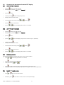
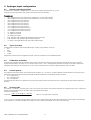
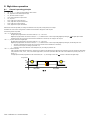
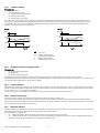
A1 to A3/A8= 4: input associated with an immediate defrost from external contact
When the corresponding digital input is closed, a defrost is started, according to the criteria set for the type “d” parameters. Possible applications: this function is useful when
defrosts need to be performed on a series of utilities coordinated by an external timer. To avoid simultaneous defrosts, the parameter “d5” can be used to delay the start of the
defrost on each unit. Another use of the function is to prevent defrosts on the units accessible to the public during opening times.
DefRqt
Key
DefRqt
Def1
Def2
Def3
d5
dP
t
Def1
Def2
Def3
t
dP
d5
t
dP
d5
dP
Defrost call
Defrost on unit 1
Defrost on unit 2
Defrost on unit n°3
Defrost start delay from controller power on or on from digital input
Maximum defrost time
t
Fig. 3
•
•
•
•
•
A1 to A3/A8= 5: door switch
This function is used to manage the door switch on a cold room. When the contact (door) is opened, the control functions and the fans are stopped and the light
output is activated. When the contact closes the unit starts again in the previous operating mode, delaying any temperature alarms for a number of hours equal
to the value of the parameter “d8”. If the door, and consequently the contact, remain open for a time greater than “d8”, the display shows the alarm code “dr”
and the controller returns to the operating mode it was in prior to the opening of the door. Specifically:
1. if the controller was in Duty Setting mode, it returns to Duty Setting;
2. if the controller was in continuous cycle mode, it returns to continuous cycle mode, and the maximum duration of the continuous cycle is not affected by
the time the door was open;
3. if the controller was in defrost mode, it remains in defrost mode;
When the controller is restarted, the set safety times are observed (see type “c” parameters).
A1 to A3/A8= 6: remote ON/OFF
By setting the input for this function the controller can be switched on/off using an external contact. Switching off is not equivalent to disconnecting power, but rather is a “logical
Off”, that is, the controller goes into “standby”, ignoring all the digital inputs and outputs, the defrost requests, continuous cycle and Duty Setting. The controller
however still continues to display the temperature, alternating with the message “Off” on the PST display, or the message “UNIT OFF” on the PGD display.
1. Contact closed= controller ON; 2. Contact open= controller OFF.
A1 to A3 /A8= 7: curtain switch
The digital input set to this value is used to activate/deactivate the “light” relay output when the corresponding contact is opened/closed. In addition, if the
parameter “Stn” is set to 1, the set point will be varied by the value of the parameter “r4”.
A1 to A3/A8= 8: “duty cycle setting” operation
The opening of the contact associated with the digital input set with this value will switch the controller to “duty setting” operation
A1 to A3/A8= 9: door switch with control ON
The behaviour of the controller when the digital input set to this value is opened is the same as for the “door switch” (An = 5) with the difference that in this
case the outputs remain active (ON). This configuration can be used in cases where the door is opened and closed frequently, for short periods (frozen food
display cabinets, etc...).
Code +03P220221 rel. 1.0 dated 28/10/05
11
4. Analogue input configuration
4.1
General operating principle
The MasterCase2 controller has 7 analogue inputs, 3 of which can be configured using parameters /S1, /S2, /S3.
Each input can be associated with the type of probe connected and an offset for the reading.
Parameters used
•
“/B1”, configuration of the type of probe /S6 (not managed in the 1st version of the software)
•
“/B2”, configuration of the type of probe /S7 (not managed in the 1st version of the software)
•
“/B3”, configuration of the type of probe /S4
•
“/B4”, configuration of the type of probe /S5
•
“/B5”, configuration of the type of probe /S1
•
“/B6”, configuration of the type of probe /S2
•
“/B7”, configuration of the type of probe /S3
•
“/S1”, configuration of the function of probe S1
•
“/S2”, configuration of the function of probe S2
•
“/S3”, configuration of the function of probe S3
•
“/C”, calibration of probe B5
•
“/d”, calibration of probe B6
•
“/8”, calibration of probe B7
•
“PUO”, calibration of the superheated gas temperature probe (suction probe)
•
“PAO”, calibration of the saturated evaporation temperature probe
•
“/4”, defines a virtual probe between the room probe and the third probe
4.2
Types of probes
The MasterCase2 controller correctly manages different types of probes, using parameters “/B1 to /B7”:
•
NTC
•
0-5V
•
PT1000
•
4-20mA
All the probes connected cannot be configured in all modes; see the list of parameters for more detailed information.
4.3
Calibration and offset
Each input can be assigned a value that is added to (positive value) or subtracted from (negative value) the temperature measured by the probe. For example, to
decrease the temperature by 2.3 degrees, set -2.3. The offset can be set from -–9.9 to +9.9 with precision to the tenth of a degree. For the probes relating to the
management of the electronic valve, the offset may vary from -9.9 to 19.9 with precision to the tenth of a degree (parameters “PUO” and “PAO”).
4.4
Control probes
The configuration of the control probes can be customised using parameters “S1”, “S2” and “S3”, assigning a different association between the room probe, defrost
probe and third probe and the physical inputs B4, B5 and B6; the default configuration associates the physical inputs as follows:
•
B4 = room probe (S1)
•
B5 = defrost probe (S2)
•
B6 = third probe (S3)
The manual often uses the term S1 to indicate the room probe, S2 the defrost probe and S3 the third probe; this is valid naturally only for the default configuration of
the board.
4.5
Virtual probe
The parameter “/4” defines a non-existent probe used for the normal control functions This parameter determines the weighted average used to calculate the
reference control probe value based on the reading of the room probe and the third probe.
The formula is the following:
virtual probe=
(100 − (" / 4" )) xS1 + (" / 4" ) xS 3
;
100
where S1=room probe and S3=third probe
If “/4” is set to 0, the virtual probe coincides with the room probe; if set to 100, the virtual probe coincides with the third probe. If control is based on the virtual probe
(value of parameter “/4” between 0 and 100), the breakage of one of the two probes automatically moves control to the other probe.
Code +03P220221 rel. 1.0 dated 28/10/05
12
5. Digital output configuration
5.1
General operating principle
The MasterCase2 series instruments have eight digital outputs that can be configured using parameters o1, o2, o3, o4, o5, o6, o7, o8 (hereinafter o1 to o8)
associated respectively with the outputs from DO1 to DO8.
Multiple outputs can be configured with the same function, thus acting as “repeats”.
Parameters used
•
“o1”, configuration of digital output 1
•
“o2”, configuration of digital output 2
•
“o3”, configuration of digital output 3
•
“o4”, configuration of digital output 4
•
“o5”, configuration of digital output 5
•
“o6”, configuration of digital output 6
•
“o7”, configuration of digital output 7
•
“o8”, configuration of digital output 8
The following describes the operation corresponding to each value of o1 to o8:
0 = “REGULATION”, control
1 = “FAN”, fans
2 = “DEFROST EVAP 1”, defrost evaporator 1
3 = “DEFROST EVAP 2”, defrost evaporator 2
4 = “LIGHT/NIGHT BLIND”, light, curtain outputs
5 = “TRIM HEATER”, heaters
6 = “ALARM”, alarm signals
7 = “ON/OFF SOLENOID”, solenoid
8 = “NET COMPRESSOR”, network compressor
9 = “NONE”, output not used
6. Other settings
6.1
H parameters
Parameters used
•
“H0”, supervisor serial address
•
“H3”, enable ON/OFF function from terminal
•
“H4”, enable ON/OFF function from supervisor
•
“Sn”, number of slave units in the LAN
As regards the parameters “H0” and “Sn”, see further on in the manual under the chapter “Network functions”.
Parameter “H3”, if set to 1, enables a screen on the PGD terminal used to switch the unit on/off.
Parameter “H4”, if set to 1, enables the unit to be switched on and off from the supervisor.
Important: the two functions, despite being able to act at the same time, are not independent. If the unit is switched off from the terminal, it cannot then be switched
back on from the supervisor and vice-versa. In practice, the two functions must be considered as being in “series”.
Code +03P220221 rel. 1.0 dated 28/10/05
13
7. Temperature control
7.1
General operating principle
Parameters used
•
“/4”, control probe
•
“St”, set point
•
“rd”, differential (hysteresis)
•
“r1”, minimum set point
•
“r2”, maximum set point
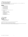
Control is performed as follows:
temperature “/4” > “St” + “rd” Ö control ON
temperature “/4” ≤ “St”
Ö control OFF
Key
Reg
t
St
rd
Reg
St
rd
Control status
Time
Set point
Differential
t [°C]
Fig. 4
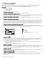
7.2
Safety parameters and control activation times
Parameters used
•
“c0”, control start delay when switching the instrument on
•
“c1”, minimum time between two consecutive starts
•
“c2”, minimum off time
•
“c3”, minimum on time
•
“c8”, control start delay from when the valve opens
7.2.1
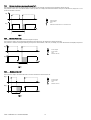
Control start delay when switching the instrument on (“c0”)
This parameter is used to delay, by a set time in minutes, the activation of the control functions from when the instrument is switched on.
Pwr
t
Rqt
Key
Pwr
Rqt
Reg
t
c0
t
Reg
t
C0
Fig. 5
Code +03P220221 rel. 1.0 dated 28/10/05
14
Enable control (Sys ON)
Control request
Control status
Time
Control start delay when switching the instrument on
7.2.2
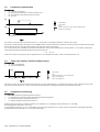
Minimum time between two consecutive starts (“c1”)
Sets the minimum time that must elapse between two activations of the controller, irrespective of the temperature and the set point.
This parameter can be set so as to limit the number of starts per hour. For example, if the maximum number of starts per hour allowed is 10, simply set c1=6 to
ensure that this limit is observed.
Rqt
Key
Rqt
Reg
t
c1
t
Reg
Control request
Control status
Time
Minimum time between two consecutive starts
t
C1
Fig. 6
7.2.3
Minimum off time (“c2”)
Sets the minimum controller off time in minutes (compressor output).
The compressor output is not reactivated until the minimum time selected (c2) has elapsed since the last deactivation.
This parameter is useful for ensuring the balancing of the pressure after shutdown, in the case, for example, of systems with hermetic and capillary compressors.
Rqt
Key
Rqt
Reg
t
c2
t
Control request
Control status
Time
Minimum off time
Reg
c2
t
Fig. 7
7.2.4
Minimum on time (“c3”)
Sets the minimum control on time.
The compressor output is not deactivated unless it has been activated for at least the time set.
Rqt
Key
Rqt
Reg
t
c3
t
Reg
t
c3
Fig. 8
Code +03P220221 rel. 1.0 dated 28/10/05
15
Control request
Control status
Time
Minimum on time
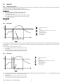
7.3
Continuous cycle function
Parameters used
•
“cc”, continuous cycle duration
•
“c6”, low temperature alarm bypass time after continuous cycle
•
“AL”, low temperature alarm (deviation from the set point)
•
“St”, set point
Rqt
Key
Rqt
Reg
t
CC rqt
cc
t
Reg
t
cc
CC rqt
Control request
Control status
Time
Instant of continuous cycle procedure activation request
Continuous cycle duration
Fig. 9
The continuous cycle function forces operation for the time “cc”, for the purpose of lowering the temperature, even below the set point.
This function is started manually by pressing the “UP” and “DOWN” buttons on the user interface for more than five seconds, both on the PST terminal and on the PGD
terminal; clearly the function cannot be activated using the PST display only (as there are no buttons).
If cc=0, the continuous cycle is disabled, the controller exits the continuous cycle procedure when the time set for the parameter “cc” has elapsed, or alternatively
when reaching the minimum temperature threshold set using the parameter “AL”.
TLIMIT = “St”-”AL”
At the end of continuous cycle operation, the low temperature alarm “L0” is disabled for the duration, in hours, indicated by parameter “c6”.
7.4
“Duty cycle setting” function (safety control)
Parameters used
•
“c4”, Safety control (ON time)
•
“c5”, Safety control (OFF time)
Reg
rE
c4
c5
Key
Reg
t
rE
c4
c5
Control status
Time
Control probe broken or not connected alarm
Safety control (ON time)
Safety control (OFF time)
Fig. 10
This function is used to keep the utility operating even when there is a control probe fault (alarm “rE”). Specifically, this function is used to decide the control on time
(c4) and off time (c5).If the alarm “rE” is reset, control restarts normally again without requiring the intervention of the maintenance personnel.
7.5
Temperature monitoring
Parameters used
•
“r5”, enable maximum and minimum temperature recording
•
“rt”, time elapsed since starting to monitor the maximum and minimum temperature
•
“rH”, maximum temperature recorded in the interval “rt”
•
“rL”, minimum temperature recorded in the interval “rt”
Enables temperature monitoring, recording the maximum (“rH”) and minimum (“rL”) temperature reached in the interval “rt” (max 999h).
The monitoring function starts when “r5” is set to 1.
To stop temperature monitoring, set “r5” to 0. After 999 hours, the max and min temperatures are no longer recorded, as the maximum monitoring time allowed by
the instrument has been reached. Reset “r5” to start the monitoring again.
Code +03P220221 rel. 1.0 dated 28/10/05
16
8. Night-time operation
8.1
General operating principle
Parameters used
•
“A1” to “A3” = 7; input associated with the curtain switch
•
“r6”, night-time control with third probe (S3)
•
“r4”, deviation from the set point
•
“Stn”, select night-time set point mode
•
“St”, set point
•
“hSn”, night-time set point start hour
•
“mSn”, night-time set point start minutes
•
“hSd”, night-time set point end hour
•
“msd”, night-time set point end minutes
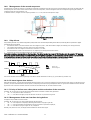
MasterCase2 offers the possibility to manage two different control set points, during the day and at night.
Parameter Stn can be used to configure the controller for the automatic changeover of the set point.
The following values are possible:
“Stn” = 0, no night-time set point.
No digital input programmed as the curtain switch (Ax ≠ 7) Ö no action.
Digital input programmed as the curtain switch (Ax = 7) Ö when the status of the corresponding digital input changes, only the light output will be
activated (action sent across the local network from the Master to the Slaves). No change in the set point.
“Stn” = 1, set point variation from digital input.
No digital input programmed as the curtain switch (Ax ≠ 7) Ö no action.
Digital input programmed as the curtain switch (Ax = 7) Ö when the status of the corresponding digital input changes, the following will occur:
•
activation of the light output (action sent across the local network from the Master to the Slaves);
•
variation of the set point, according to parameter “r4”;
•
switching of the control reference to the third probe (S3), according to parameter “r6”.
“Stn” = 2, variation from RTC.
If the controller is fitted with the RTC option, operation can switch from the daytime to the night-time set point and vice-versa by setting two time bands
(see parameters “hSm”, “mSn”, “hSn”, hSd” and the figure below). The actions performed will be the same as described in the previous point (“Stn”=1
and Ax=7).
If a digital input has been programmed as the curtain switch (Ax = 7), the change in status will only activate or deactivate the light output.
temperature
St1
r4
St
hSn, mSn
hSd, mSd
Fig. 11
Code +03P220221 rel. 1.0 dated 28/10/05
17
t
9. Fans
9.1
General operating principle
The operation of the fans can be divided into four phases:
1. Normal operation
2. Defrost
3. Dripping
4. Post-dripping
9.2
Normal operation
Parameters used
•
“F0”, fan operating mode
•
“F1”, fan off time
•
“F2”, fan operation based on the control status
•
“A0”, temperature alarm return and fan activation differential
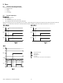
During normal operation the fans can be managed by the “fan controller”, which manages them according to the temperature measured by the end defrost probe (S2)
where “F1” =0, or alternatively can be always on, and stop when the controller is switched off, based on the settings of parameters “F2”, where “F0”=0.
“F0”=0, “F2”=0
“F0”=0, “F2”=1
Pwr
Pwr
t
t
Reg
Reg
t
t
Fan
Fan
t
t
Fig. 12
Fig. 13
“F0”=1
Pwr
t
Reg
t
Temp
Key
Pwr
Reg
Fan
Temp
F1
A0
F1
F1-A0
t
Fan
t
Fig. 14
Code +03P220221 rel. 1.0 dated 28/10/05
18
Enable control (Sys ON)
Control status
Status of the fans
Temperature
Fan off time
Temperature alarm return and fan activation differential
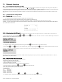
9.3
Defrost, dripping, post-dripping
Parameters used
•
“F3”, fan management during defrost
•
“Fd”, fan off time during post-dripping
•
“dd”, dripping time
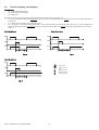
During defrost, the fans can be configured to operate in different modes, based on the value of parameter “F3”:
•
F3=0, fans on during defrost. During the dripping wait (in the case of master-slave network defrost) and dripping times (if set by the parameter “dd”) the fans
are always off.
•
F3=1, fans always off in all phases, defrost and dripping wait.
•
F3=2, fans always on, even during the dripping phase (“dd”). This is useful in the applications where the fans must always be on, yet a “pause”/dripping time is
required after defrosting. During the dripping wait (in the case of master-slave network defrost) and dripping times (if set by the parameter “dd”) the fans are
always on.
F0=0, F3=0, Fd ≠ 0
F0=0, F3=1, Fd ≠ 0
Reg
Reg
t
Def
t
Fan
dF
dd
Fd
t
Def
t
Fan
t
dF
dd
Fig. 15
Fig. 16
F0=0, F3=2, Fd ≠ 0
Reg
Key
Reg
Fan
t
dF
dd
Fd
t
Def
t
Fan
dF
dd
Fd
t
Fig. 17
Code +03P220221 rel. 1.0 dated 28/10/05
t
Fd
19
Control status
Status of the fans
Time
Defrost operation
Dripping wait time
Post-dripping time
10.
Defrost
10.1
General operating principle
Parameters used
•
All the type “d” parameters
•
“/10”, select end defrost probe
•
“/9”, end defrost also with third probe (S3)
•
“r3”, enable alarm “Ed” (defrost ended by timeout)
The defrost function has the task of removing any frost or ice on the evaporator, optimising energy consumption and maximising performance.
MasterCase2 offers different types of programmable defrosts:
•
cyclical defrost;
•
defrost from Real Time Clock;
•
defrost at instrument start-up.
There are also different types of forced defrosts:
•
manual defrost from LAN;
•
manual local defrost;
•
defrost from digital input.
The following types of defrost are available (these can be selected using parameter “d0”):
•
heater, end by temperature or after a maximum safety time (timeout)
•
hot gas, end by temperature or after a maximum safety time (timeout)
•
heater, end by time
•
hot gas, end by time
If parameter “r3”=1, when the defrost procedure ends after having reached the maximum time (“d0” = 0 or 1), the “Ed” alarm is signalled to indicate a possible
problem.
N.B.: All the defrosts, except for the local manual defrosts, are transferred from the master to the slaves over the pLAN network.
10.2
Structure of the defrost function
The defrost procedure features three phases:
•
“Actual” defrost
•
Dripping wait
•
Post-dripping
Reg
Key
Reg
Def
dF
dd
Fd
t
Def
t
Fan
dF
dd
Fd
t
Fig. 18
Code +03P220221 rel. 1.0 dated 28/10/05
20
Control status
Status of the defrost output
Defrost operation (actual defrost)
Dripping wait time
Post-dripping time
10.3
“Actual” defrost
Parameters used
•
“d0”, type of defrost
•
“/10”, select end defrost probe
•
“/9”, end defrost also with third probe (S3)
•
“dP”, maximum defrost duration
•
“dt”, maximum defrost temperature
The “actual” defrost phase is the main phase of the defrost procedure; only during this phase is the heater output or hot gas injection solenoid valve activated.
The duration of this phase depends on the configuration of parameter “d0”, which indicates whether the end of the actual defrost procedure depends only on the
maximum defrost time “dP”, or also on the temperature indicated as the end defrost temperature “dt”, according to the value read by the probe indicated by
parameter “/10” and the configuration of parameter “/9”.
d0=0/2
d0=1/3
Reg
Reg
t
TDEF
dt
t
t
Def
Def
t
dP
Fig. 19
t
Fig. 20
Key
Reg
Def
TDEF
dP
dt
10.4
t
TDEF
dt
Control status
Status of the defrost output
End defrost probe temperature
Maximum defrost duration
Maximum defrost temperature
Dripping and post-dripping times
Parameters used
•
“F3”, fan management during defrost
•
“dd”, dripping time
•
“Fd”, fan off time during post-dripping
This phase allows the water created due to the heat from the electric heaters to drip, choosing whether the fans should be on at the same time.
The dripping phase lasts the time indicated by parameter “dd”; during the dripping phase, the fans operate based on the setting of parameter “F3”. For further details
on the dripping and post-dripping phases, see the section on the fans.
10.5
Cyclical defrost
MasterCase2 offers the possibility to configure “cyclical” defrosts, that is, defrosts that are repeated cyclically over time. Parameter “dI” manages this type of defrost,
with the procedure being repeated after the number of hours set with this parameter. The time is restarted whenever a defrost is completed (even non-cyclical ones).
If “dI” is equal to 0 (“dI” = 0), cyclical defrosts are disabled.
In a LAN, the activation of a cyclical defrost on the master also activates a defrost on the connected Slaves (network defrost).
10.6
Defrost on start-up
This functions activates a defrost when the instrument is switched on, based on the setting of parameter “d4”.
This function can be useful when, due to frequent power failures and the consequent resetting of the defrost timer (see parameter “dI”), the number of planned
defrosts may be reduced and therefore be insufficient. In multi-utility systems, to avoid the simultaneous defrosting of all the units when power returns, set parameter
“d5”, corresponding to the defrost delay, to different values.
10.7
Network defrost
With each programmed or forced defrost, except for the local manual defrosts, the Master unit transfers the defrost call to all the Slave units; the various instruments
in the pLAN network can be programmed to also wait for the end defrost signal from the network.
This setting depends on parameter “d2”:
•
“d2” = 0 Î the instrument completes the defrost without waiting for the end signal (stand-alone instrument);
•
“d2” = 1 Î the instrument waits, at the end of the defrost, for the end signal, which is usually sent by the master in a LAN of multiplexed cabinets; the end
signal arrives when all the units in the network have completed the actual defrost phase.
Code +03P220221 rel. 1.0 dated 28/10/05
21
10.8
Management of the second evaporator
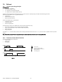
The MasterCase2 controller can manage a second defrost output that is independent from the main one and associated with the value read by the third probe (S3).
Consequently, this can be used to control a defrost heater on the second evaporator, with the management of the second evaporator bypassing the end defrost
configuration with two probes (parameter “/9”).
To enable the function, configure one of the outputs (parameters “o1” to “o8”) as the second evaporator output.
aux1
Two independent defrost outputs
Fig. 21
10.9
Skip defrost
This parameter (parameter “d7”) enables the algorithm by which, based on the actual time elapsed during the last defrost, the following defrost is performed or skipped.
The following rules are considered:
•
the maximum number of consecutive defrosts that can be skipped is 3, that is, after the third defrost skipped, the following one is always performed;
•
after switching the instrument on, the first 7 defrosts are always performed;
•
the number of events to be skipped is increased by a maximum of 1 at a time;
•
the manual defrosts (started on the user interface) or by digital input are always performed and counted;
•
the function can only be used with the defrosts that end by temperature.
This function is based on a very simple but very effective principle. If the defrost lasts less than or equal to 70% of the time set for the parameter “dP” (maximum
defrost time), the next defrost envisaged will be skipped. When the following defrost is performed, the check is repeated, and if the outcome is the same then the
following two defrosts envisaged are skipped, and so on according to the criteria described above (maximum 3 successive defrosts skipped).
As soon as the defrost time exceeds 70% of the time “dP”, the following defrost will be performed and the function will start again.
DefRqt
<70%
Key
DefRqt
JmpSbr
<70%
JmpSbr
DefRqt
<70%
>70%
Defrost call
Defrosts skipped
<70%
Fig. 22
This function should be used with the programming of the defrosts equally distributed over the day (e.g. cyclical defrosts, parameter “dI”).
10.10 HI alarm bypass after defrost
During the defrost phase, and in the period immediately following the defrost, the control probe reading may reach temperature values that are not allowed in normal
operation, yet may be allowable in these transition phases; consequently, the unnecessary high temperature alarm “HI” signal can be disabled for the time indicated
by parameter “d8”. If the alarm condition continues more than the time indicated by “d8”, the alarm will be activated.
10.11 Priority of defrost over safety times and the activation of the controller
Parameter “d9” can be used to assign the priority between the defrost call and the controller safety parameters.
•
“d9” = 0 Ö the protection times are observed;
•
“d9” = 1 Ö the defrost has higher priority and the times set with the “C” parameters are ignored.
10.12 Management of the user interface during defrost
Configuration only available for the PST terminal.
Parameter “d6” can be used to set what is displayed during the defrost phase:
•
“d6” = 0 Ö the temperature is displayed, alternating with the defrost in progress signal “dF”;
•
“d6” = 1 Ö the last temperature measured before the start of the defrost procedure is displayed;
•
“d6” = 2 Ö the defrost in progress signal “dF” only is displayed.
Naturally, if any alarms are active, the display selected will alternate with the alarm signal.
Code +03P220221 rel. 1.0 dated 28/10/05
22
11.
Electronic valve
11.1
General operation
MasterCase2 can manage the operation of an electronic expansion valve with stepper motor (Carel E2V) or a PWM On/Off valve.
This allows the possibility to directly control the injection of refrigerant into the evaporator, with lower and more stable superheat values, higher evaporation
temperatures and consequently greater humidity and a more constant temperature, guaranteeing better product conservation and quality.
Parameters used
•
All type “P” parameters
11.2
Configuration of the system parameters
Select the type of valve (“P1”)
The MasterCase2 controller can control two different types of valve. Parameter P1 is used to set the model installed.
•
“P1” = 0, “PWM”, PWM valve;
•
“P1” = 1, “STEPPER”, Valve with stepper motor;
•
“P1” = 2, “NONE”, Valve not installed.
Note: Whenever this parameter is modified, the control will need to be switched off and on again, so as to load the internal values associated with the type of valve
chosen.
Refrigerant (“PH”)
Parameter “PH” sets the type of refrigerant used on the unit. This setting is required for the calculation of the saturated evaporation temperature. For refrigerants with
glide, the dew point is used.
Superheat set point (“P3”)
Parameter “P3” indicates the superheat control set point.
Dead band (“P2”)
Parameter “P2” indicates the dead band, that is, the semi-interval of temperatures (±) around the superheat set point in which there are no control actions.
For example, a value of 1°C for this parameter with a set point of 5°C means that the superheat can vary between 4°C and 6°C without the controller attempting to
modify it. Obviously, if the superheat value is outside of this interval, the controller would immediately be activated.
Proportional gain, Integral time, Derivative time
The proportional (parameter “P4”), integral (parameter “P5”) and derivative (parameter “P6”) constants are the main control parameters. These define the superheat
PID control algorithm. Refer to classic PID control theory for a more detailed description of their meaning.
Note: The proportional constant – Kp – defines the gain not only for the PID control but also for all the active protection functions (LOW SHeat protection, LOP
protection, MOP protection, HiTcond protection).
LOW SuperHeat
Low subcooling threshold.
Parameter “P7” defines the activation threshold for the low superheat protection function. Below this value another control function is activated, in addition to the PID,
with programmable constant (parameter “P8”).
When this threshold is crossed, the timer (parameter “P9”) starts for the low superheat alarm, if activated.
MOP
High suction pressure threshold (Maximum Operating Pressure) indicated in saturated °C.
Parameter “PM1” defines the high pressure protection activation threshold. Above this value, integral control starts, using a constant that can be set (parameter
“PM2”) so as to maintain the saturated suction temperature below the set value.
Note: The MOP protection tends to CLOSE the expansion valve. This means that if the reason why a high pressure situation occurred is temporary (compressor start,
sudden variation in the refrigerant charge, modulation of the cooling capacity, etc.) the refrigerant superheat temperature on the suction side may be low or drop
quickly. In these cases, the MOP protection and the superheat control act together, and there are no limits to either. If, on the other hand, the high pressure has been
reached at the same time as particularly high or normal superheat values (for example the unit was started with very high temperatures of the product being cooled),
the unlimited and extended action of the MOP may involve a refrigerant suction temperature that is excessive for the correct operation of the compressor. For this
reason, a limit has been introduced to the maximum superheat temperature, described below (high suction temperature threshold).
MOP delay at start
This is the delay time for the activation of the MOP protection function whenever the control is activated (both when the unit is started and whenever deviating from
the set point). It can be set using parameter “PM3”. This allows regular restarts before activating the MOP function.
High suction temperature threshold
Parameter “PM4” sets the maximum temperature (thermometric) allowed for the gas leaving the evaporator.
This parameter therefore limits the action of the MOP protection so that, when reached, the corrective action of the protection function is stopped, until the refrigerant
temperature returns below the set value.
Type and range of the saturation temperature probe
Parameter “PSt” selects the mode used to read the suction temperature; when PSt = 0 the saturation temperature is read by the pressure probe (the operating limits
can be set by the parameters “PEL” and “PEH”) and then converted to a temperature. When PSt = 1, the temperature is read directly by the connected probe.
Parameters “PUO” and “PAO” can be used to define an offset on the temperature read by the two probes.
Code +03P220221 rel. 1.0 dated 28/10/05
23
12.
HACCP
12.1
General operation
This function allows advanced control of the operating temperature and the recording of any faults due to power failures or increases in the operating temperature for
various reasons (faults, severe operating conditions, user errors, etc...).
This function can only be activated on the controllers with the RTC option fitted.
Parameters used
•
“Ad”, “tr”, temperature alarm delay and HACCP alarm delay
•
“AH”, high temperature alarm (deviation from the set point)
•
“tA”, type of HACCP alarm
•
“tSH”, “tSM”, “tSd”, “tSm”, HACCP alarm start hour, minutes and date
•
“tEH”, “tEM”, “tEd”, “tEm”, HACCP alarm end hour, minutes and date
•
“to”, delete the saved data
Alarms generated
•
“HF”
•
“HA”
12.2
HA alarm
T
Key
T
t
St
AH
tr
To
HA
HAt
St+AH
HA
tr+Ad
Temperature control probe
Time
Set point
High temperature alarm (deviation from the set point)
HACCP alarm delay
Temperature alarm delay
HA alarm (HACCP)
HA alarm duration
t
HAt
Fig. 23
If, during operation, the temperature measured is greater than the threshold represented by the sum of the parameters “AH” (high temperature alarm threshold) and
“St” (set point), for a time greater than the sum of the parameter “tr” (specific for the HACCP alarms) and the parameter “Ad” (temperature alarm delay), the alarm
HA is activated.
When the event occurs the following data are saved:
•
hour, minutes and day, month, year the alarm condition started;
•
type of alarm;
•
maximum temperature reached after the activation of the alarm;
•
hour, minutes and day, month, year the alarm condition ended.
12.3
HF alarm
T
Key
T
t
St
AH
tr
To
HF
HFt
St+AH
HF
HFt
Temperature control probe
Time
Set point
High temperature alarm (deviation from the set point)
HACCP alarm delay
Temperature alarm delay
HF alarm (HACCP)
HF alarm duration
t
Fig. 24
This is activated after a power failure if, when power returns, the temperature is higher than the threshold represented by “AH” + “St”. The following data are saved:
•
hour, minutes and day, month, year the power failure ended;
•
type of alarm;
•
maximum temperature reached after the activation of the alarm;
•
hour, minutes and day, month, year the alarm condition ended.
Code +03P220221 rel. 1.0 dated 28/10/05
24
13.
Network functions
13.1
Local network operation (pLAN)
The MasterCase2 controllers can be connected together to form a pLAN (pCO Local Area Network) in master-slave configuration. The main purpose of the pLAN is to
provide communication and synchronisation in operation between a series of instruments (maximum six: one Master and five Slaves) operating on a multi-evaporator utility,
for example a multiplexed cabinet. The configuration of the instruments can be modified by simply setting the network address.
This configuration is used to synchronise and coordinate the defrosts, send the status of the digital inputs and display any alarms active relating to the Slaves on the
Master.
13.2
13.2.1
•
•
pLAN network configuration
Parameters used
“Sn”, Number of slave units (only on the master)
“Sj”, Select the unit in the pLAN connected to the display (only on the PGD terminal)
On the Master unit, the number of units connected in the LAN can be configured using parameter “Sn”.
The Master function will be automatically taken by the controller configured with address 1 in the pLAN network. All the other units act as slaves.
Parameter “Sj” can be used to change the unit in the network displayed on the terminal; the function for selecting the unit in the network displayed on the terminal is
only available with the PGD terminal.
+--------------------+
|Switch to
Sj|
|unit
|
|SLAVE1
|
|Current Unit:MASTER |
+--------------------+
13.2.2
Setting the address of the PGD0 terminal
The address of the terminal can only be set after having supplied power to the terminal via the RJ12 telephone connector. The default address of the terminal is 32.
To enter configuration mode, press the DOWN
UP
displayed, with the cursor flashing in the top left corner:
and ENTER
buttons at the same time for at least 5 seconds; the following screen will be
• To change the address of the terminal (display address setting) press ENTER
. The cursor will move to the address field (nn).
• Use the DOWN
and UP
buttons to select the desired value, and confirm by pressing ENTER
. If the value selected is different from the one saved
previously, the following screen will be displayed, and the new value will be saved to the permanent memory on the display.
If the field nn is set to 0, the terminal will communicate with the controller using the “point-to-point” protocol (not pLAN) and the “I/O Board address: xx” field is no
longer displayed, being without meaning.
13.2.3
Setting the address of the boards in the pLAN
The pLAN address is set using a standard PGD0 terminal, as follows:
• Disconnect the board from the power supply;
• Prepare a PGD0 terminal with the address set to 0;
• Connect the terminal to the controller;
• Disconnect any pLAN connections to other controllers from the MasterCase2;
• Power the controller by pressing the UP
and ALARM
• After a few seconds the following screen will be displayed:
• To change the address, simply use the UP
Code +03P220221 rel. 1.0 dated 28/10/05
and DOWN
buttons at the same time;
buttons and then press ENTER
25
to confirm.
13.3
Downloading the parameters
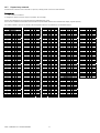
All the instruments in the MasterCase2 series have the possibility of transferring the parameter settings from the master to the slaves across the pLAN local network.
This operation is used to save time in programming the instruments that are used in the same LAN and that would have similar settings.
During the transfer phase, all the parameters are downloaded from the master to the slaves, except for those that involve the individual controller (clock setting,
defrost times, etc.…). The following list summarises the parameters that are transferred via pLAN from the Master to the Slaves; for a more detailed description of
each individual parameter, see the table of parameters.
/10
/4
/7
/9
/B1
/B2
/B3
/B4
/B5
/B6
/B7
/S1
/S2
/S3
/SL1
/t
A0
A7
Ad
AH
AL
13.4
c0
c1
c2
c3
c4
c5
c6
c8
cc
CP1
d0
d2
d3
d4
d5
d6
d7
d8
d9
dd
dI
dM
dP
dPM
dt
F0
F1
F2
F3
Fd
H3
H4
P1
P2
P3
P4
P5
P6
P7
P8
P9
PEH
PEL
PH
PL1
PL2
PM1
PM2
PM3
PM4
PPE
Pst
r1
r2
r3
r4
r5
r6
rd
St
tr
Failed download signal
When the parameter download procedure starts, a screen is displayed indicating the results of the download.
For each slave unit present in the network, the message “No” is displayed if there has been a communication error (download failed), while if the download is
successful, the message “Ok” is displayed.
+--------------------+
|Download Result
|
|
|
|Sl1:Ok Sl3:Ok Sl5:- |
|Sl2:No Sl4:|
+--------------------+
13.5
Network defrost in multiplexed systems
One of the functions that mostly requires synchronisation is defrost management. The master controls the defrosts on all the slaves connected. The master waits for
all the units to have ended the defrost before signalling the end of the defrost on the entire network. The slaves that have ended the defrost wait for the end defrost
signal from the master before starting the dripping phase. Once having received the end defrost signal, the controllers switch to the dripping phase. The defrost on
each single unit and the network defrost in any case end after the maximum defrost time, set by parameter (“dP”, default 30 min.).
The network defrost, as well as being run cyclically at a programmable interval using parameter “dI”, can be started:
•
From the PGD0 terminal by pressing ENTER and DOWN together for more than 5 seconds;
•
From the PST terminal by pressing the SET
•
button on the PST for more than 5 seconds starts the local defrost on the unit.
N.B.: Pressing the DOWN button on PGD0 or the
At pre-set times, if the RTC option is fitted on the Master unit.
13.6
and
buttons together for more than 5 seconds
Remote alarm signals
The unit configured as the master in a LAN can signal remote alarms present on the slave units, if enabled by setting the corresponding configuration parameter
(parameter Ar = 1). All the masters are enabled to receive the alarm signals from the slaves by default.
As the terminal or display is not essential for the operation of the unit, and indeed in a LAN the slave can operate perfectly without this user interface, this function is
particularly useful for "centralising" the alarm management functions on the master.
If the master detects an alarm on a slave unit (probe error, high or low temperature error, etc....), the display shows the corresponding alarm signal. The following
codes denote an alarm on the slave units:
1. Alarm on slave unit 1 = n1
2. Alarm on slave unit 2 = n2
3. Alarm on slave unit 3 = n3
4. Alarm on slave unit 4 = n4
5. Alarm on slave unit 5 = n5
The alarm relay on the master is activated when the remote alarm signal remote is received.
Code +03P220221 rel. 1.0 dated 28/10/05
26
13.7
Supervisory network
The MasterCase2 controllers can be connected to a supervisor, allowing remote control of the entire installation.
Parameters used
•
“H0”, supervisor serial address
To configure the supervisory network, simply set parameter “H0” accordingly.
The unit can be interfaced to a local or remote supervisory/telemaintenance system.
The accessories available for the MasterCase2 board include an optional RS485 or Ethernet serial communication adapter, supplied separately.
The variables available to supervisor are shown in the following table. See the list of parameters for an extended description:
Ref.
Idx
T
Digital variables
MP1
1
D
MP2
2
D
MP3
3
D
MP4
4
D
MP5
5
D
MP6
6
D
MP7
7
D
MP8
8
D
MP
9
D
On/Off
10
D
Rtc Present
11
D
r3
12
D
r5
13
D
r6
14
D
F0
15
D
F2
16
D
Fd
17
D
d4
18
D
Ar
19
D
d7
20
D
d9
21
D
/9
23
D
H3
25
D
Comp
26
D
Light
27
D
Def
28
D
Fan
29
D
Def2
30
D
Alarm
31
D
Thea
32
D
NetComp
33
D
On/Off
34
D
HI
40
D
LO
41
D
Ed
43
D
Ed1
44
D
Id
45
D
dA
46
D
IA
47
D
HA
48
D
HF
49
D
E1
50
D
E2
51
D
E3
52
D
Flow
RW
RW
RW
RW
RW
RW
RW
RW
RW
RW
R
RW
RW
RW
RW
RW
RW
RW
RW
RW
RW
RW
RW
R
R
R
R
R
R
R
R
R
R
R
R
R
R
R
R
R
R
R
R
R
Ref.
T
Flow
Ref.
Idx
T
Flow
rE
53
D
LO1
54
D
N1
55
D
N2
56
D
N3
57
D
N4
58
D
N5
59
D
Res HACCP
60
D
PSt
61
D
No haccp alr
62
D
MOP
63
D
dr
64
D
tC
65
D
MA
66
D
U1
67
D
U2
68
D
U3
69
D
U4
70
D
U5
71
D
LOP
72
D
LSh
73
D
HSh
74
D
Integer Variables
Ad
1
I
A1
2
I
A2
3
I
A3
4
I
A4
5
I
A7
6
I
A8
7
I
H0
8
I
/10
9
I
Sn
12
I
Stn
13
I
hSn
14
I
hSd
15
I
F3
16
I
d2
17
I
c0
18
I
c1
19
I
c2
20
I
c3
21
I
c4
22
I
c5
23
I
c6
24
I
R
R
R
R
R
R
R
RW
RW
R
R
R
R
R
R
R
R
R
R
R
R
R
c8
cc
d0
d5
d8
dd
dI
dP
dM
dPM
/t
/4
/7
/S1
/S2
/S3
d1
d2
d3
d4
d5
d6
d7
d8
h1
h2
h3
h4
h5
h6
h7
h8
m1
m2
m3
m4
m5
m6
m7
m8
PH
tr
tA
tSH
tSM
25
26
27
29
30
31
32
33
34
35
36
37
38
39
40
41
42
43
44
45
46
47
48
49
50
51
52
53
54
55
56
57
58
59
60
61
62
63
64
65
66
70
71
72
73
I
I
I
I
I
I
I
I
I
I
I
I
I
I
I
I
I
I
I
I
I
I
I
I
I
I
I
I
I
I
I
I
I
I
I
I
I
I
I
I
I
I
I
I
I
RW
RW
RW
RW
RW
RW
RW
RW
RW
RW
RW
RW
RW
RW
RW
RW
RW
RW
RW
RW
RW
RW
RW
RW
RW
RW
RW
RW
RW
RW
RW
RW
RW
RW
RW
RW
RW
RW
RW
RW
RW
RW
R
R
R
Code +03P220221 rel. 1.0 dated 28/10/05
Idx
RW
RW
RW
RW
RW
RW
RW
RW
RW
RW
RW
RW
RW
RW
RW
RW
RW
RW
RW
RW
RW
RW
27
Ref.
Idx
T
tSD
74
I
tSm
75
I
tSy
76
I
tEH
77
I
tEM
78
I
tED
79
I
tEm
80
I
tEy
81
I
/B1
82
I
/B2
83
I
/B3
84
I
/B4
85
I
/B5
86
I
/B6
87
I
/B7
88
I
P9
90
I
th
100
I
t
101
I
tn
102
I
tm
103
I
ty
104
I
td
105
I
PF
116
I
Power Rqt
117
I
d6
118
I
rt
119
I
mSn
120
I
mSd
121
I
P1
122
I
CP1
123
I
PM3
124
I
Analogue Variables
AH
1
A
AL
2
A
A0
3
A
St
4
A
rd
5
A
r1
6
A
r2
7
A
r4
8
A
SL1
9
A
F1
10
A
dt
11
A
/8
12
A
Flow
Ref.
Idx
T
Flow
R
R
R
R
R
R
R
R
RW
RW
RW
RW
RW
RW
RW
RW
R
R
R
R
R
R
R
R
RW
R
RW
RW
RW
R
R
/C
/d
P2
P3
P4
P5
P6
P7
P8
PM1
PM2
PM4
Po1
Po4
PL
Po3
Po2
Air off prb
Defrost prb
Air on prb
Virtual Prb
/10 prb
tt
rH
rL
PPE
PEL
PEH
PUO
PAO
PL1
PL2
13
14
15
16
17
18
19
20
21
22
23
24
25
26
27
28
29
30
31
32
33
34
40
60
61
62
63
64
65
66
67
68
A
A
A
A
A
A
A
A
A
A
A
A
A
A
A
A
A
A
A
A
A
A
A
A
A
A
A
A
A
A
A
A
RW
RW
RW
RW
RW
RW
RW
RW
RW
RW
RW
RW
R
R
R
R
R
R
R
R
R
R
R
R
R
RW
RW
RW
RW
RW
RW
RW
RW
RW
RW
RW
RW
RW
RW
RW
RW
RW
RW
RW
14.
Alarms
14.1
Summary table
Ref.
rE
E1
E2
E3
Screen description
Control probe broken or not
connected
Air Off probe broken or not
connected
Defrost probe broken or not
connected
Air on probe broken or not
connected
E0
IA
dA
L0
HI
HA
HF
Ed
Ed1
LSh
dF
tC
MA
u1
u2
u3
u4
u5
n1
n2
n3
n4
n5
Id
dr
Immediate external alarm
Delayed external alarm
Low temperature alarm
High temperature alarm
HACCP alarm
HACCP alarm
Defrost ended by timeout
Driver probes out of range
Low SuperHeat alarm
dF
RTC invalid
Lost communication with master
Lost communication with slave 1
Lost communication with slave 2
Lost communication with slave 3
Lost communication with slave 4
Lost communication with slave 5
Alarm on slave 1
Alarm on slave 2
Alarm on slave 3
Alarm on slave 4
Alarm on slave 5
Duty cycle setting from digital
input
Timeout door open
Code +03P220221 rel. 1.0 dated 28/10/05
Meaning
Control probe/probes broken or not connected
Relay alarm and buzzer
Active
(S1) Room probe broken or not connected
Relay only
(S2) Defrost probe broken or not connected
Relay only
(S3) Third probe broken or disconnected
Relay only
Communication error with the PST terminal
(only on PST display)
Immediate external alarm
Delayed external alarm
Low temperature alarm
High temperature alarm
HA alarm (HACCP)
HF alarm (HACCP)
Defrost ended by timeout
Driver control probes broken or not connected
Low superheat
Defrost in progress (only on PST display)
RTC error
Lost communication with the master
Lost communication with slave unit 1
Lost communication with slave unit 2
Lost communication with slave unit 3
Lost communication with slave unit 4
Lost communication with slave unit 5
Alarm on slave unit 1
Alarm on slave unit 2
Alarm on slave unit 3
Alarm on slave unit 4
Alarm on slave unit 5
Duty cycle setting alarm from digital input
Not active
Door open alarm
28
Active
Active
Active
Active
Relay only
Relay only
Relay only
Active
Active
Not active
Active (only on units with RTC)
Active (only on the slaves)
Active (only on the master unit)
Active (only on the master unit)
Active (only on the master unit)
Active (only on the master unit)
Active (only on the master unit)
Active (only on the master unit)
Active (only on the master unit)
Active (only on the master unit)
Active (only on the master unit)
Active (only on the master unit)
Active
Relay only
14.2
Notes and descriptions
MasterCase2 offers the possibility to signal any faults both using the alarm LED on the terminal and the buzzer (PST terminal only), as well as, in the case of serious
alarms, by activating a relay with changeover contacts for the remote alarm signal; each alarm signal is sent to the supervisor, allowing real time monitoring even from
a remote location.
The alarms can be divided into groups:
•
Alarms relating to the probes
•
Alarms relating to the electronic valve
•
Temperature alarms
•
HACCP alarms
•
Alarms relating to communication between the units
•
Alarms relating to the digital inputs
•
Other signals
14.2.1
Alarms relating to the probes
Check the parameters: “/4”, “/S1…/S3”, “/B1…/B7”, “PSt”, “PEL”, “PEH”.
rE
Control probe error:
•
probes not working: the probe signal is interrupted or short-circuited;
•
probes not compatible with the instrument.
If control is based on the virtual probe (value of parameter "/4" between 0 and 100), this error will be generated only when both the probes are broken. In fact, the
breakage of just one of the two probes automatically moves control to the other probe.
E1
Room probe error:
•
probe not working: the probe signal is interrupted or short-circuited;
•
probe not compatible with the instrument.
E2
Evaporator probe error:
•
probe not working: the probe signal is interrupted or short-circuited;
•
probe not compatible with the instrument.
E3
Third probe error:
•
probe not working: the probe signal is interrupted or short-circuited;
•
probe not compatible with the instrument.
E0
Communication error with the PST terminal.
This error may arise if there is no communication between the controller and the terminal, even if power to the latter is supplied by the controller.
Ed1
Superheat probes out of range.
The valve is controlled by reading the superheat, which in turn is the difference between the value measured by the evaporator probe (either pressure or temperature,
depending on parameter “PSt”) and the suction temperature probe. If these probes are faulty or out-of-range, the controller is no longer able to manage the valve, and
control is terminated, signalling the presence of a serious alarm:
•
check the electrical connections;
•
check the condition of the probes.
14.2.2
Alarms relating to the electronic valve
Check the parameters: “P1”, “PH”, “P7”, “P9”, “PM1”, “PM4”.
LSh
Low superheat. When the threshold set by parameter “P7” is exceeded, a delay set for parameter “P9” starts, after which this alarm is generated:
•
check the mechanical condition of the valve;
•
check that the readings and the positions of the probes are correct.
14.2.3
Temperature alarms
Check the parameters: “AL”, “AH”, “Ad”, ”St” and “A0”.
LO
Low temperature alarm.
The control probe has detected a temperature lower than the set point by a value greater than parameter "AL":
•
check the correct operation of the temperature probes.
The alarm is reset automatically when the temperature returns within the set limits (see parameters “AL” and “A0”).
HI
High temperature alarm.
The control probe has detected a temperature higher than the set point by a value greater than parameter “AH”:
•
check the correct operation of the temperature probes.
The alarm is reset automatically when the temperature returns within the set limits (see parameters “AH” and “A0”).
Code +03P220221 rel. 1.0 dated 28/10/05
29
14.2.4
HACCP alarms
Check the parameters: “St”, “Ad”, “AH”, all the type “t” parameters.
See the HACCP section in the manual.
HA
HACCP alarm, type HA.
A high temperature alarm has occurred according to the settings of parameters “tr”, “Ad”, “AH”, “St”:
•
check the HACCP parameters;
•
check the temperature and the correct operation of the temperature probes.
HF
HACCP alarm, type HF.
A high temperature alarm has occurred according to the settings of parameters “tr”, “AH”, “St”.
A power failure has occurred for more than one minute and when power returned the temperature was higher than the value set for “AH” + “St”:
•
check the HACCP parameters;
•
check the temperature and the correct operation of the temperature probes.
14.2.5
Alarms relating to communication between the units
Check the parameters: “Sn”, setting the unit address in the LAN.
See the “Network functions” section in the manual.
MA (on slave)
Loss of communication with the master on the slave:
•
check the LAN electrical connections.
These network signals (both on the master and on the slaves) are reset automatically as soon as communication is re-established between the master and the slaves.
“u1 to u5” (on master)
Loss of communication with slave 1 to 5:
•
check the LAN electrical connections.
These network signals (both on the master and on the slaves) are reset automatically as soon as communication is re-established between the master and the slaves.
14.2.6
Alarms relating to the digital inputs
Check the parameters: “A1 to .A3”, “A8” and “A7”.
IA
Immediate alarm from digital input:
•
check the status of the digital input and the value of the corresponding parameter “A1 to .A3” / “A8”.
dA
Delayed alarm from digital input:
•
check the status of the digital input and the value of the corresponding parameters “A1 to A3” / “A8” and “A7”.
Id
This is an immediate external alarm (see the description of alarm “IA”), with the difference that the controller will activate the “duty cycle setting” function (see
explanation of parameters “c4” and “c5”):
•
check the status of the digital input and the value of the corresponding parameter “A1 to A3” / “A8”.
14.2.7
Other signals
Check the parameters: “r3”, “dP”, “d0”, “d8”, “d6”, “Ar”, ”th”, “t’”, “tn”, “tM”, “tY” and “td”.
Ed
The last defrost ended as the maximum time (parameter “dP”) exceeded, before reaching the end defrost temperature (“dt”). The signal is active only if parameter
“r3”= 1. The signal remains on until a defrost is completed correctly as programmed and that ends at the set temperature:
•
check parameters “r3”, “d0”, “dt” and “dP”;
•
check the efficiency of the defrost devices;
•
check the positioning of the end defrost probe.
dr
The digital input configured as the “door switch” (“A1 to A3”, “A8” = 5) has remained open for a time greater than the time set for parameter “d8”:
•
check that the door is actually closed;
•
check the status of the contact connected to the input on the instrument.
dF
Defrost running:
•
this is not an alarm signal, but rather an indication that the controller is running a defrost;
•
it is only displayed if parameter d6= 0, or d6= 2.
“n1 to n5” (on master)
Local alarm on slave 1 to 5:
•
check the status of the slave with the alarm and check the alarm code on the slave.
tC
Clock error (RTC) on the unit fitted with the RTC:
•
set the time and the minutes on the user interface or via supervisor;
•
if the error persists, check and/or replace the clock card.
Code +03P220221 rel. 1.0 dated 28/10/05
30
(Prb) Probe parameters
Ref. Screen description
Virtual probe
/4
configuration
RW
C
/7 Remote display type
RW
C
/8 S3 probe calibration
RW
C
Description
Defines a virtual probe between the room probe and the third probe.
0 = The value of the virtual probe is the same as the room probe
1 to 99 = The value of the virtual probe is between the room probe and the third probe
100 = The value of the virtual probe is the same as the third probe
Select the remote display
0 = SMALL KEYPAD, PST small with three buttons
1 = READ-ONLY, PST small display only
Calibration of probe S3
Select end defrost mode also with third probe (S3). The defrost ends:
0 = DISABLED, when the temperature of the probe selected by /10 is greater than the end defrost
temperature “dt”
1 = ENABLED, when both the temperature of the probe selected by /10 and the temperature of the third
probe are greater than the end defrost temperature “dt”
Select the probe used to end the defrost procedure
0 = VIRTUAL
1 = AIR OFF PROBE (room probe)
2 = DEFROST PROBE
UOM
Range
Default
15.1
Access
level
List of parameters
Type
15.
-
0 to 100
0
-
0 to 1
0
°C
-9.9 to
9.9
0
-
0 to 1
0
-
0 to 2
2
End defrost with air
/9
on probe
RW
C
/10 End defrost probe
RW
F
RW
C
Calibration of probe S1
°C
RW
C
Calibration of probe S2
°C
/C
/d
S1 probe calibration
S2 probe calibration
User interface
management
RW
/S1
S1 probe
configuration mode
RW
C
/S2
S2 probe
configuration mode
RW
C
/S3
S3 probe
configuration mode
RW
C
/t
/B1 S6 probe type
RW
C
/B2 S7 probe type
RW
C
/B3 S4 probe type
RW
Select the probe displayed on the main screen
NOT PRESENT, no probe
AIR OFF PROBE (room probe)
DEFROST PROBE
AIR ON PROBE (third probe)
REGULATION PROBE (virtual probe)
Configuration of the function of probe S1
0 = NOT PRESENT
1 = AIR OFF PROBE (room probe)
2 = DEFROST PROBE
3 = AIR ON PROBE (third probe)
Configuration of the function of probe S2
0 = NOT PRESENT
1 = AIR OFF PROBE (room probe)
2 = DEFROST PROBE
3 = AIR ON PROBE (third probe)
Configuration of the function of probe S3
0 = NOT PRESENT
1 = AIR OFF PROBE (room probe)
2 = DEFROST PROBE
3 = AIR ON PROBE (third probe)
0=
1=
C
2=
3=
4=
C
Select the type of probe S6
0 = NTC
1 = 0-5Vdc
2 = PT1000
3 = 4-20mA
Select the type of probe S7
0 = NTC
1 = 0-5Vdc
2 = PT1000
3 = 4-20mA
Select the type of probe S4
0 = NTC
1 = 0-5Vdc
2 = PT1000
Code +03P220221 rel. 1.0 dated 28/10/05
31
-9.9 to
9.9
-9.9 to
9.9
0
0
-
0 to 4
4
-
0 to 3
1
-
0 to 3
2
-
0 to 3
3
For future applications.
Currently not managed
-
0 to 3
0
For future applications.
Currently not managed
-
0 to 3
0
-
0 to 2
0
/B4 S5 probe type
RW
C
/B5 S1 probe type
RW
C
/B6 S2 probe type
RW
C
/B7 S3 probe type
RW
C
Description
0
-
0 to 2
0
-
0 to 2
0
3.0
-
-20.0 to
20.0
0 to 1
-
0 to 1
0
°C
2.0
°C
°C
hours
0.1 to
20.0
0 to 999
Description
UOM
Range
°C
r2
r3
Maximum set point value
Alarm for defrost end timeout
RW
RW
C
C
°C
-
r4
Automatic variat. to night-time
setpoint
Min and max temp. monitoring
enabling
RW
C
Maximum set point value allowed by the user
Enable “Ed” alarm (defrost ended by timeout)
0 = DISABLED
1 = ENABLED
Night-time set point (deviation from the set point)
RW
C
r6
Night-time regulation with air on
probe
RW
C
rd
Regulation differential
RW
F
Enable maximum and minimum temperature recording
0 = DISABLED
1 = ENABLED
Night-time control with third probe (S3)
0 = DISABLED, night-time control on virtual probe
1 = ENABLED, night-time control on third probe (S3)
Value of the differential (hysteresis) used for temperature control.
rH
rL
rt
Max temperature stored
Min temperature stored
Temperature storing interval
R
R
R
C
C
C
Maximum temperature recorded in the interval “rt”
Minimum temperature recorded in the interval “rt”
Time elapsed since starting to monitor the maximum and minimum temperature
°C
90.0
0
0
0
Regulation starting delay
Minimum time beetween two start
of the same comp
Minimum comp OFF time
Minimum comp ON time
Relay safety Time ON on error
Relay safety Time OFF on error
Low temperature alarm exclusion
after cc
Delay start regulation after
valve open
Continuous cycle duration
Default
c0
c1
Type
Screen description
Access
level
(cMP) Safety time and control activation parameters
Ref.
cc
0 to 2
-50.0
Minimum set point value allowed by the user
c8
-
-50.0 to
r2
r1 to 90.0
0 to 1
C
c6
0
Range
RW
c2
c3
c4
c5
0 to 2
UOM
Minimum set point value
15.3
-
Default
Screen description
r1
r5
Range
(rEG) Control parameters
Type
Ref.
UOM
Select the type of probe S5
0 = NTC
1 = 0-5Vdc
2 = PT1000
Select the type of probe S1
0 = NTC
1 = 0-5Vdc
2 = PT1000
Select the type of probe S2
0 = NTC
1 = 0-5Vdc
2 = PT1000
Select the type of probe S3
0 = NTC
1 = 0-5Vdc
2 = PT1000
Access
level
15.2
Description
Default
Access
level
Type
Ref. Screen description
RW
RW
C
C
Control start delay from power up
Minimum time between two consecutive starts
min
min
0 to 15
0 to 15
0
0
RW
RW
RW
RW
C
C
C
C
min
min
min
min
0 to 15
0 to 15
0 to 100
0 to 100
0
0
0
0
RW
C
Minimum off time
Minimum on time
Safety control (“Duty cycle setting” function) ON time
Safety control (“Duty cycle setting” function) OFF time
Displayed if C4≠0
Low temperature alarm bypass time after continuous cycle
hours
0 to 15
2
RW
C
Control start delay from when the valve opens
s
0 to 120
5
RW
C
Continuous cycle duration
hours
0 to 15
4
Code +03P220221 rel. 1.0 dated 28/10/05
32
Description
d0
Defrost type
RW
C
d2
LAN defrost command type
RW
C
d4
Defrost at startup
RW
C
d5
d6
Defrost delay from digital input
Display control during defrost
RW
RW
C
C
d7
Enable skip
defrost
RW
C
d8
High temperature alarm exclusion
after defrost/door
Defrost priority on the compressor
protection
Dripping time after defrost
Interval between two defrost
Maximum duration
of a defrost
Defrost end temperature
RW
F
Type of defrost:
0 = ELECTRIC; END BY TEMPERATURE, OTHERWISE BY TIME
1 = HOTGAS; END BY TEMPERATURE, OTHERWISE BY TIME
2 = ELECTRIC; END BY TIME
3 = HOTGAS; END BY TIME
Type of control for LAN defrost
0 = START ONLY
1 = START AND STOP
Defrost when switching controller on
0 = DISABLED
1 = ENABLED
Defrost start delay from controller power on or on from digital input
Display management during defrost
0 = TEMP+DF, display the temperature alternating with the symbol “dF”
1 = FIXED TEMPERATURE, hold on last temperature displayed;
2 = dF, display the message “dF”( PST only).
Enable “skip defrost” function
0 = DISABLED
1 = ENABLED
High temperature alarm bypass time after defrosting and/or door open
RW
C
Priority of defrost over protection times
RW
RW
RW
F
F
F
Dripping time
Interval between two consecutive defrosts
Maximum defrost time
RW
F
End defrost temperature
dt
15.5
A0
Screen description
Fan and alarm differential
A1...3 Digital input 1...3 configuration
A7
A8
Ad
AH
AL
Ar
-
0 to 3
0
-
0 to 1
1
-
0 to 1
0
min
-
0 to 180
0 to 2
0
0
-
0 to 1
0
min
0 to 600
60
-
0 to 1
0
min
hours
min
0 to 15
0 to 192
0 to 180
2
8
30
°C
-50.0 to
30.0
4.0
UOM
Range
°C
2.0
-
0.1 to
20.0
0 to 9
min
0 to 180
180
min
0 to 9
0 to 180
0 to 20.0
0 to 20.0
0 to 1
0
120
0.0
0.0
1
(ALr) Alarm parameters
Type
Ref.
Range
Detection delay time for delayed
alarm input
Virtual digital input configuration
Temperature alarm delay
High temperature alarm
Low temperature alarm
Slave remote alarm signal enabling
on master
RW
C
RW
C
RW
C
RW
RW
RW
RW
RW
C
C
F
F
C
Code +03P220221 rel. 1.0 dated 28/10/05
Description
Temperature alarm return and fan activation differential
(see parameters F1, AH and AL)
Configuration of digital inputs 1 to 3 (see note 1)
0 = None
1 = Remote alarm
2 = Remote delayed alarm
3 = Enable defrost
4 = Start ext defrost (immediate defrost from external contact)
5 = Door switch
6 = Remote on/off
7 = Blind switch (curtain switch)
8 = Start duty setting
9 = Door switch regul.on, (door switch with control ON)
Alarm delay from digital input (A1 to 3 = 2)
Virtual digital input configuration (see parameters A1...3)
Temperature alarm delay
High temperature alarm (deviation from the set point)
Low temperature alarm (deviation from the set point)
Enable the master to signal the slave alarms
(only on the master)
33
°C
°C
-
Default
dd
dI
dP
Access
level
d9
UOM
Default
Screen description
Type
Ref.
(dEF) Defrost management parameters
Access
level
15.4
0
F0
Fan management
RW
Description
C
Fan management
UOM
Range
-
0 to 1
0
°C
5.0
-
-40.0 to
50.0
0 to 1
-
0 to 2
1
min
0 to 15
1
UOM
Range
-
0 to 199
0 to 1
0 to 1
0 to 9
1
1
0
-
-
0 to 5
0
UOM
Range
°C
-
r1 to r2
0 to 2
-20.0
0
hours
min
hours
min
0 to 23
0 to 59
0 to 23
0 to 59
0
0
0
0
Default
Screen description
Type
Ref.
(FAn) Evaporator fan management parameters
Access
level
15.6
0 = ALWAYS ON (except in cases F2, F3, Fd)
1 = THERMOSTAT CONTROLLED, fans controlled based on absolute set point F1
F1
Fan start-up absolute setpoint
RW
F
F2
Fans off with compressor off
RW
C
Fan off time
Fans off when control off
1
0 = DISABLED
1 = ENABLED
F3
Fans manage during defrost
RW
C
Fd
After dripping fan stopping
RW
F
Sn
15.8
Number of slaves
RW
RW
RW
RW
C
C
C
C
RW
C
Supervisor serial address
Enable ON/OFF from terminal
Enable ON/OFF from supervisor
Configuration of digital outputs 1 to 8
0 = REGULATION ( control)
1 = FAN
2 = DEFROST EVAP 1
3 = DEFROST EVAP 2
4 = LIGHT/NIGHT BLIND (light, curtain output)
5 = TRIM HEATER
6 = ALARM
7 = ON/OFF SOLENOID
8 = NET COMPRESSOR
9 = NONE
Number of slaves (only on the master)
0 = LAN not present
Default
(SEt) Set point parameters
Screen description
Type
Ref.
Serial address (Supervisor)
Enable On/Off from keyboard
Enable On/Off from supervisor
Digital Output 1...8 configuration
St
Stn
Temperature setpoint
Select night setpoint type
RW
RW
F
C
hSn
mSn
hSd
hSd
Night setpoint starts at
Night setpoint starts at
Night setpoint stops at
Night setpoint stops at
RW
RW
RW
RW
C
C
C
C
Code +03P220221 rel. 1.0 dated 28/10/05
Description
Set point
Select night-time set point mode
0 = NONE
1 = FROM DIGITAL INPUT (See A1 to 3=7)
2 = FROM RTC
Night-time set point start hour
Night-time set point start minutes
Night-time set point end hour
Night-time set point end minutes
34
Default
H0
H3
H4
o1…8
Description
Access
level
Screen description
Type
Ref.
(CnF) Configuration parameters
Access
level
15.7
Active only if F0= 0
Fan management during defrost
0 = FANS ON, OFF IN dd, fans on, off during dripping (“dd”)
1 = FANS ALWAYS OFF
2 = FANS ALWAYS ON, fans on even during the dripping phase (“dd”)
Fan off time during post-dripping
(HcP) HACCP parameters
tr
HACCP alarm delay
RW
Description
F
HACCP alarm delay
UOM
Range
min
0 to 180
0
-
0 to 2
0
Default
Screen description
Type
Ref.
Access
level
15.9
3 = HACCP disabled
tA
tSH
tSM
tSd
tSm
tSY
tt
tEH
tEM
tEd
tEm
tEY
to
Haccp alarm type
Haccp alarm start
Haccp alarm start
Haccp alarm start
Haccp alarm start
Haccp alarm start
Max temperature during haccp alarm
Haccp alarm end at
Haccp alarm end at
Haccp alarm end at
Haccp alarm end at
Haccp alarm end at
Reset haccp history
R
F
R
R
R
R
R
R
R
R
R
R
R
RW
F
F
F
F
F
F
F
F
F
F
F
F
Type of HACCP alarm
4 = no alarm
5 = HA alarm
6 = HF alarm
HACCP alarm start hours
HACCP alarm start minutes
HACCP alarm start day
HACCP alarm start month
HACCP alarm start year
Maximum temperature reached during the most recent HACCP alarm
HACCP alarm end hours
HACCP alarm end minutes
HACCP alarm end day
HACCP alarm end month
HACCP alarm end year
Delete the data saved
°C
-
-50.0 to 90.0 -50.0
0 to 1
0
Access
level
th
t’
tn
tM
tY
td
Hour
Hour
Date
Date
Date
Date
RW
RW
R
RW
RW
RW
F
F
F
F
F
F
d1
1^ defrost time
RW
C
h1
M1
d2
h2
m2
d3
h3
m3
d4
h4
m4
d5
h5
m5
d6
h6
m6
1^ defrost time
1^ defrost time
2^ defrost time
2^ defrost time
2^ defrost time
3^ defrost time
3^ defrost time
3^ defrost time
4^ defrost time
4^ defrost time
4^ defrost time
5^ defrost time
5^ defrost time
5^ defrost time
6^ defrost time
6^ defrost time
6^ defrost time
RW
RW
RW
RW
RW
RW
RW
RW
RW
RW
RW
RW
RW
RW
RW
RW
RW
C
C
C
C
C
C
C
C
C
C
C
C
C
C
C
C
C
Ref.
Screen description
Code +03P220221 rel. 1.0 dated 28/10/05
Description
Current hours
Current minutes
Current weekday
Current month
Current year
Current day
Weekday of 1st defrost
0 = ***, no setting
1 = MONDAY
2 = TUESDAY
3 = WEDNESDAY
4 = THURSDAY
5 = FRIDAY
6 = SATURDAY
7 = SUNDAY
8 = MONDAY TO FRIDAY
9 = WEEK-END
10 = ALL DAYS
Hours of 1st defrost
Minutes of 1st defrost
Weekday of 2nd defrost (see parameter d1)
Hours of 2nd defrost
Minutes of 2nd defrost
Weekday of 3rd defrost (see parameter d1)
Hours of 3rd defrost
Minutes of 3rd defrost
Weekday of 4th defrost (see parameter d1)
Hours of 4th defrost
Minutes of 4th defrost
Weekday of 5th defrost (see parameter d1)
Hours of 5th defrost
Minutes of 5th defrost
Weekday of 6th defrost (see parameter d1)
Hours of 6th defrost
Minutes of 6th defrost
35
UOM
Range
Default
Type
15.10 (rtc) RTC parameters (Real Time Clock)
-
0 to 23
0 to 59
0 to 12
0 to 9
0 to 31
-
-
0 to 10
0
hours
min
hours
min
hours
min
hours
min
hours
min
hours
min
0 to 23
0 to 59
0 to 10
0 to 23
0 to 59
0 to 10
0 to 23
0 to 59
0 to 10
0 to 23
0 to 59
0 to 10
0 to 23
0 to 59
0 to 10
0 to 23
0 to 59
0
0
0
0
0
0
0
0
0
0
0
0
0
0
0
0
0
RW
RW
RW
RW
RW
RW
C
C
C
C
C
C
Description
Weekday of 7th defrost (see parameter d1)
Hours of 7th defrost
Minutes of 7th defrost
Weekday of 8th defrost (see parameter d1)
Hours of 8th defrost
Minutes of 8th defrost
UOM
Range
Default
7^ defrost time
7^ defrost time
7^ defrost time
8^ defrost time
8^ defrost time
8^ defrost time
Access
level
d7
h7
m7
d8
h8
m8
Screen description
Type
Ref.
hours
min
hours
min
0 to 10
0 to 23
0 to 59
0 to 10
0 to 23
0 to 59
0
0
0
0
0
0
UOM
Range
-
0 to 2
0
-
0 to 10
2
s
%
°C
°C
S
s
°C
s
s
°C
3.0 to 10.0
0 to 100
0 to 9.9
0 to 50.0
0 to 99.9
0 to 250
0 to 99.9
-10.0 to P3
0 to 25.0
0 to 9999
-50.0 to
70.0
0 to 25.0
0 to 250
0 to 999.9
0 to 1
6.0
80
0
12.0
10.0
100
0.0
5.0
15.0
0
60.0
P1
EEV Type
RW
Description
Access
level
Screen description
Type
Ref.
C
Type of valve
Default
15.11 (EEv) Valve parameters
7 = PWM, valve with PWM control
8 = STEPPER, valve with step control
9 = NOT PRESENT
PH
Refrigerant Type
RW
C
PPE
CP1
P2
P3
P4
P5
P6
P7
P8
P9
PM1
PWM period
Start-up EEV opening
SuperHeat Dead zone
SuperHeat Set
PID Proportional factor
PID Integral factor
PID Derivative factor
Low SuperHeat threshold
Low SuperHeat Integral time
Alarms delay Low SuperHeat
MOP protection Threshold
RW
RW
RW
RW
RW
RW
RW
RW
RW
RW
RW
C
C
C
C
C
C
C
C
C
C
C
PM2
PM3
PM4
PSt
MOP protection Integral time
MOP protection Start-up delay
Suction temp. high limit
Evaporation satured temperature
from
RW
RW
RW
RW
C
C
C
C
PEL
RW
C
RW
C
PUO
Evaporation pressure probe
Min value
Evaporation pressure probe
Max value
Suction temp. Offset
RW
C
Integral time during the MOP (valve closing)
MOP function activation delay
Maximum superheated gas temperature
Evaporation temperature read by
0 = PRESSURE, if the evaporation pressure probe is used
1 = TEMPERATURE, if the evaporation temperature probe is used
Minimum value of the evaporator probe.
Available only if PSt=0
Maximum value of the evaporator probe.
Available only if PSt=0
Temperature offset of the suction probe
PAO
Satured temp. Offset
RW
C
Temperature offset of the saturation probe
PEH
Code +03P220221 rel. 1.0 dated 28/10/05
Type of refrigerant:
0 = R22
1 = R134a
2 = R404a
3 = R407c
4 = R410a
5 = R507
6 = R290
7 = R600
8 = R600a
9 = R717
10 = R744
Period of the PWM signal
Initial valve position
Dead band
Superheat set point
PID proportional gain
PID integral time
PID derivative time
Low superheat threshold
Low superheat integral time
Low superheat alarm delay time
MOP threshold (saturated evaporation temperature)
36
s
s
°C
-
bar
bar
°C
°C
-1.0 to
40.0
-1.0 to
90.0
-9.9 to
19.9
-9.9 to
19.9
10.0
120
80.0
1
-1.0
9.3
0
0
o1…8 Digital Output 1...8 configuration
RW
C
Configuration of digital outputs 1 to 8
0 = REGULATION (control)
1 = FAN
2 = DEFROST EVAP 1
3 = DEFROST EVAP 2
4 = LIGHT/NIGHT BLIND (light, curtain output)
5 = TRIM HEATER
6 = ALARM
7 = ON/OFF SOLENOID
8 = NET COMPRESSOR
9 = NONE
UOM
Range
-
0 to 9
-
UOM
Range
Default
Description
Access
level
Screen description
Type
Ref.
Default
15.12 Outputs (PGD only)
The same parameters are available as parameters o1 to o8 on the PST display, in
the CnF menu (configuration).
RW
C
Enable the manual procedure
-
0 to 1
0
RW
C
Manually enable and disable the outputs
-
0 to 1
0
UOM
Range
Default
MP
1..8
Manual procedure
Enable:
Regulation
Fan
Defrost evap 1
Defrost evap 2
Light/night blind
Trim heater
Alarm
On/off solenoid
Net compressor
Range
Default
MP
Screen description
Access
level
Ref.
Type
15.13 Service (PGD only)
Description
-
Screen description
Press ENTER to install default
parameter
Carel SpA
Cod. FLSTDmMC2O
Ver.:x.x xx/xx/xx
Boot:xx.xx xx/xx/xx
Bios:xx.xx xx/xx/xx
Access
level
Ref.
Type
15.14 Initialisation (PGD only)
RW
C
Press ENTER to activate the default value installation procedure
Use with caution.
R
C
Version, code and release date of the application.
R
R
C
C
MasterCase2 boot firmware version
MasterCase2 bios firmware version
Description
-
-
-
Screen description
Press ENTER to switch the unit
status
Access
level
Ref.
Type
15.15 Unit ON/OFF (PGD only)
RW
C
Code +03P220221 rel. 1.0 dated 28/10/05
Description
Change the unit status.
Available only if H3=1
UOM
-
37
Sj
Switch to unit
RW
C
Sn
Number of slaves
RW
C
Description
Switch the terminal to another unit in the LAN.
Only the available units are displayed:
10 = MASTER
11 = SLAVE 1
12 = SLAVE 2
13 = SLAVE 3
14 = SLAVE 4
15 = SLAVE 5
This function is not featured on the PST terminal.
Number of slaves (only on the master)
0 = LAN not present
UOM
Range
Default
Screen description
Access
level
Ref.
Type
15.16 Network (PGD only)
-
0 to 5
Unit
current
-
0 to 5
0
Note 1
Value of A1 to
A3/A8
Meaning
0
1
2
Input not active
Immediate external alarm
Delayed external alarm
3
Enable defrost
4
Immediate activation of the defrost
Door switch
5
6
7
Remote ON/OFF
Curtain switch
8
“Duty cycle setting” from external contact
9
Door switch with control ON
Code +03P220221 rel. 1.0 dated 28/10/05
Operation
No function associated
Contact open = alarm active
Contact open = alarm active with delay set by parameter “A7”.
Contact open = defrost not enabled
Contact closed = defrost enabled
Contact closed = start immediate defrost.
Contact open = door open.
When the door is opened the controller and the fans stop. If the door remains open for a time greater than
the value set for parameter “d8”, the controller and the fans start again and an error is signalled (“dr”).
Contact closed = unit ON (on);
Contact open = unit OFF (unit in standby).
Contact closed = night curtain closed.
See parameters “Stn”, “r4” and “r6”.
Contact closed = activation of the “duty cycle setting” (see parameters “c4” and “c5”).
Contact open = deactivation, return to normal control.
As for function 5, but the controller remains active.
38
CAREL S.p.A.
Via dell’Industria, 11 - 35020 Brugine - Padova (Italy)
Tel. (+39) 049.9716611 Fax (+39) 049.9716600
http://www.carel.com - e-mail: [email protected]
Code: +03P220221 rel. 1.0 dated 28/10/05
Agency: