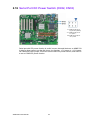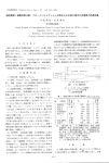
1
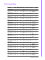
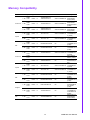
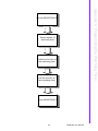
User Manual AIMB-769 AIMB-769 Socket LGA775 Intel® Core™ 2 Quad ATX with VGA, 2 COM and Single LAN Safety Information Electrical safety To prevent electrical shock hazard, disconnect the power cable from the electrical outlet before relocating the system. When adding or removing devices to/from the system, ensure that the power cables for the devices are unplugged before the signal cables are connected. If possible, disconnect all power cables from the existing system before you add a device. Before connecting or removing signal cables from the motherboard, ensure that all power cables are unplugged. Seek professional assistance before using an adapter or extension cord. These devices could interrupt the grounding circuit. Make sure that your power supply is set to the correct voltage in your area. If you are not sure about the voltage of the electrical outlet you are using, contact your local power company. If the power supply is broken, do not try to fix it by yourself. Contact a qualified service technician or your retailer. Operation safety Before installing the motherboard and adding devices on it, carefully read all the manuals that came with the package. Before using the product, make sure all cables are correctly connected and the power cables are not damaged. If you detect any damage, contact your dealer immediately. To avoid short circuits, keep paper clips, screws, and staples away from connectors, slots, sockets and circuitry. Avoid dust, humidity, and temperature extremes. Do not place the product in any area where it may become wet. Place the product on a stable surface. If you encounter technical problems with the product, contact a qualified service technician or your retailer. Caution! The symbol of the crossed out wheeled bin indicates that the product (electrical and electronic equipment) should not be placed in municipal waste. Check local regulations for disposal of electronic products. AIMB-769 User Manual Part No. 2006076900 Edition 1 Printed in Taiwan July 2011 ii A Message to the Customer Advantech Customer Services Each and every Advantech product is built to the most exacting specifications to ensure reliable performance in the harsh and demanding conditions typical of industrial environments. Whether your new Advantech equipment is destined for the laboratory or the factory floor, you can be assured that your product will provide the reliability and ease of operation for which the name Advantech has come to be known. Your satisfaction is our primary concern. Here is a guide to Advantech’s customer services. To ensure you get the full benefit of our services, please follow the instructions below carefully. Technical Support We want you to get the maximum performance from your products. So if you run into technical difficulties, we are here to help. For the most frequently asked questions, you can easily find answers in your product documentation. These answers are normally a lot more detailed than the ones we can give over the phone. So please consult this manual first. If you still cannot find the answer, gather all the information or questions that apply to your problem, and with the product close at hand, call your dealer. Our dealers are well trained and ready to give you the support you need to get the most from your Advantech products. In fact, most problems reported are minor and are able to be easily solved over the phone. In addition, free technical support is available from Advantech engineers every business day. We are always ready to give advice on application requirements or specific information on the installation and operation of any of our products. iii AIMB-769 User Manual Declaration of Conformity FCC This device complies with the requirements in part 15 of the FCC rules: Operation is subject to the following two conditions: This device may not cause harmful interference This device must accept any interference received, including interference that may cause undesired operation. This equipment has been tested and found to comply with the limits for a Class A digital device, pursuant to Part 15 of the FCC Rules. These limits are designed to provide reasonable protection against harmful interference when the equipment is operated in a commercial environment. This equipment generates, uses, and can radiate radio frequency energy and, if not installed and used in accordance with the instruction manual, may cause harmful interference to radio communications. Operation of this device in a residential area is likely to cause harmful interference in which case the user will be required to correct the interference at his/her own expense. The user is advised that any equipment changes or modifications not expressly approved by the party responsible for compliance would void the compliance to FCC regulations and therefore, the user's authority to operate the equipment. Caution! There is a danger of a new battery exploding if it is incorrectly installed. Do not attempt to recharge, force open, or heat the battery. Replace the battery only with the same or equivalent type recommended by the manufacturer. Discard used batteries according to the manufacturer's instructions. AIMB-769 User Manual iv CPU Compatibility Mfg. Tech L2 Advantech Long Life cache PN Support CPU Family sSpec. Core Power Vcore Stepping Quad Q9650 3.0 GHz EM64T Quad Core SLB8W E0 95 W 0.8500V1333 1.3625V 45 nm 12 MB NA Core Quad Q9400 2.66GHz EM64T Quad Core SLB6B R0 95 W 0.85V1.3625V 1333 45 nm 6 MB 96MP2QDYes 26FB-6M7T Core2 Quad Q9300 2.5GHz EM64T Quad Core SLAWE Ma 98 W 0.85V1.3625V 1333 45 nm 6 MB NA No Core2 Quad Q8200 2.33 GHz EM64T Quad Core SLB5M M1 95 W 0.85V1.3625V 1333 45 nm 4 MB NA No Core2 Quad Q6600 2.4GHz EM64T Quad Core SL9UM B3 105 W 0.85V1.5V 1066 65 nm 8 MB NA No Core2 Quad Q6600 2.4GHz EM64T Quad Core SLACR B3 95 W 0.85V1.5V 1066 65 nm 8 MB 96MP2QDNo 24FA-8M7T Core2 Duo E8500 3.16GHz EM63T Dual Core SLAPK C0 65 W 0.851.3625V 1333 45 nm 6 MB 96MP2DDNo 31FB-6M7B Core2 Duo E8400 3.0GHz EM64T Dual Core SLB9J E0 65 W 0.85V1.3625V 1333 45 nm 6 MB 96MP2DDNo 3FB-6M7T1 Core2 Duo E8400 3.0GHz EM64T Dual Core SLAPL C0 65 W 0.851.3625V 1333 45 nm 6 MB 96MP2DDYes 3FB-6M7T Core2 Duo E8200 2.66GHz EM64T Dual Core SLAPP C0 65 W 0.851.3625V 1333 45 nm 6 MB NA Core2 DuoE7500 2.93GHz EM64T Dual Core SLGTE R0 65 W 0.8500V1066 V1.3625 45 nm 3 MB 96MP2DD29FANo 3M7T1 1066 45 nm 3 MB 96MP2DD28FAYes 3M7T1/ SLGW3 FSB No No Core2 Duo E7400 2.80GHz EM64T Dual Core SLB9Y R0 65 W 0.851.3625V Core2 Duo E7300 2.66GHz EM64T Dual Core SLAPB M0 65 W 0.851.3625V 1066 45 nm 3 MB NA No Core2 Duo E7200 2.53GHz EM64T Dual Core SLAVN M0 65 W 0.851.3625V 1066 45 nm 3 MB NA No Core2 Duo E6750 2.66GHz EM64T Dual Core SLA9V G0 65W 0.85-1.5V 1333 65 nm 4 MB 96MP2DDNo 26FB-4M7T Core2 Duo E6700 2.66GHz EM64T Dual Core SL9S7 B2 65 W 0.8501.3525V 1066 65 nm 4 MB 96MP2DDYes 26FA-4M7T Core2 Duo E6600 2.40GHz EM64T Dual Core SL9S8 B2 65 W 0.8501.3525V 1066 65 nm 4 MB 96MP2DDNo 24FA-4M7T Core2 Duo E6550 2.33GHz EM64T Dual Core SLA9X G0 65 W 0.962V1.350V 1333 65 nm 4 MB NA No Core2 Duo E6500 2.93GHz EM64T Dual Core SLGUH R0 65 W 0.962V1.350V 1066 45 nm 2 MB 96MPPD2.93-2M7T Yes Core2 Duo E6400 2.13GHz EM64T Dual Core SL9S9 B2 65 W 0.8501.3525V 1066 65 nm 2 MB 96MP2DDNo 21FA-2M7T v AIMB-769 User Manual Core2 Duo E6300 1.86GHz EM64T Dual Core SL9SA B2 65 W 0.8501.3525V 1066 65 nm 2 MB 96MP2DDNo 18FA-2M7T Core2 Duo E6420 2.13GHz EM64T Dual Core SLA4T B2 65 W 0.8501.5V 1066 65 nm 4 MB NA No Core2 Duo E6320 1.86GHz EM64T Dual Core SLA4U B2 65 W 0.8501.5V 1066 65 nm 4 MB NA No Core2 Duo E5300 2.6GHz EM64T Dual Core SLB9U R0 65 W 0.85V1.3625V 800 45 nm 2 MB NA Yes Core2 Duo E4700 2.6GHz EM64T Dual Core SLALT G0 65 W 1.162V1.312V 800 65 nm 2 MB NA No Core2 Duo E4500 2.2GHz EM64T Dual Core SLA95 M0 65 W 0.8501 5V 800 65 nm 2 MB NA No Core2 Duo E4400 2.0GHz EM64T Dual Core SLA3F L2 65 W 1.162V1.312V 800 65 nm 2 MB NA No Core2 Duo E4300 1.8GHz EM64T Dual Core SL9TB L2 65 W 0.85V1.5V 800 65 nm 2 MB 96MP2DDYes 18F8-2M7T Pentium Dual-Core 1.8GHz E2160 SLA8Z M0 65 W 0.85V1.5V 800 65 nm 1 MB 96MPPD1.8F81M7T Yes Pentium Dual-Core 1.6GHz E2140 SLA3J L2 65 W 1.162V1.312V 800 65 nm 1 MB NA No Celeron E1200 1.6GHz SLAQW M0 EM64T 65 W 1.162V1.312V 800 65 nm 512 KB 96MPC2No 1.6F8-5K7T Celeron 440 2GHz SL9XL A1 35 W 1.01.3375V 800 65 nm 512 KB 96MPC4Yes 2.0F8-5K7T Celeron 430 1.8GHz SL9XN A1 35 W 1.01 3375V 800 65 nm 512 KB 96MPC4No 1.8F8-5K7T Celeron 420 1.6GHz SL9XP A1 35 W 1.01 3375V 800 65 nm 512 KB NA AIMB-769 User Manual vi No Memory Compatibility Brand Transcend Size Speed Type ECC Vendor PN Advantech PN 1 GB DDR3 1066 DDR3 N TS128MLK64V1U/ TS2KNU28100-1S SEC 96D3-1G1066NN-TR K4B1G0846DHCF8 (128x8) 1 GB DDR3 1066 DDR3 N TS128MLK64V1U SEC K4B1G0846D 96D3-1G1066NN-TR HCH9 ENJ038A3 (128x8) 2 GB DDR3 1066 DDR3 N TS256MLK64V1U/ TS5KNU28300-1S SEC 96D3-2G1066NN-TR K4B1G0846DHCF9(128x8) 1 GB DDR3 1066 DDR3 N 78.01GC3.420 ELPIDA 96D3-1G1066NN-AP J1108BDBG-DJF (128x8) 2 GB DDR3 1066 DDR3 N 78.A1GC3.421 ELPIDA 96D3-2G1066NN-AP J1108BDBG-DJF (128x8) 1 GB DDR3 1066 DDR3 N D3UE28081XH18AB NA ELPIDA J1108BDSE-DJ-F (128x8) 2 GB DDR3 1066 DDR3 N D3UE28082XH18AB NA ELPIDA J1108BDSE-DJ-F (128x8) 1 GB DDR3 1333 DDR3 N TS128MLK64V3U ELPIDA 96D3-1G-1333NN-TR J1108BDBG-DJF(128x8) 1 GB DDR3 1333 DDR3 N TS128MLK64V3U NA Micron 9GF22 D9KPT (128x8) 2 GB DDR3 1333 DDR3 N TS256MLK64V3U NA SEC 907 HCH9 K4B1G08460(12 8x8) 1 GB DDR3 1333 DDR3 N 78.01GC6.420 ELPIDA 96D3-1G1333NN-AP J1108BFBG-DJF(128x8) 2 GB DDR3 1333 DDR3 N 78.A1GC6.421 ELPIDA 96D3-2G1333NN-AP J1108BDBG-DJF (128x8) 1 GB DDR3 1333 DDR3 N D3UE28081XH18AB NA ELPIDA J1108BDSE-DJ-F (128x8) 2 GB DDR3 1333 DDR3 N D3UE28082XH18AB NA ELPIDA J1108BDSE-DJ-F (128x8) 1 GB DDR3 1333 NA HYNIX H5TQ1G83BFR H9C 928AK (128x8) 2 GB DDR3 1333 DDR3 N TS128MLK64V3U NA ELPIDA J1108BDBG-DJF 093309DLK20 (256x8) 4 GB DDR3 1333 DDR3 N AQ12M64B8BKH9S NA SAMSUNG 949 K4B2G0846BHCH9 (256x8) Apacer DSL Transcend Apacer DSL DDR3 N KVR1333D3N9/1G Kingston ATP vii Memory AIMB-769 User Manual Ordering Information AIMB-769 Ordering Information Part Number Chipset Display GbE PCIe x 16 PCIe x 1 PCI AIMB-769VG-00A1E G41/ICH7 VGA 1 1 5 1 Product Warranty (2 years) Advantech warrants to you, the original purchaser, that each of its products will be free from defects in materials and workmanship for two years from the date of purchase. This warranty does not apply to any products which have been repaired or altered by persons other than repair personnel authorized by Advantech, or which have been subject to misuse, abuse, accident or improper installation. Advantech assumes no liability under the terms of this warranty as a consequence of such events. Because of Advantech’s high quality-control standards and rigorous testing, most of our customers never need to use our repair service. If an Advantech product is defective, it will be repaired or replaced at no charge during the warranty period. For outof-warranty repairs, you will be billed according to the cost of replacement materials, service time and freight. Please consult your dealer for more details. If you think you have a defective product, follow these steps: 1. Collect all the information about the problem encountered. (For example, CPU speed, Advantech products used, other hardware and software used, etc.) Note anything abnormal and list any onscreen messages you get when the problem occurs. 2. Call your dealer and describe the problem. Please have your manual, product, and any helpful information readily available. 3. If your product is diagnosed as defective, obtain an RMA (return merchandise authorization) number from your dealer. This allows us to process your return more quickly. 4. Carefully pack the defective product, a fully-completed Repair and Replacement Order Card and a photocopy proof of purchase date (such as your sales receipt) in a shippable container. A product returned without proof of the purchase date is not eligible for warranty service. 5. Write the RMA number visibly on the outside of the package and ship it prepaid to your dealer. AIMB-769 User Manual viii Initial Inspection Before you begin installing your motherboard, please make sure that the following materials have been shipped: AIMB-769 Socket LGA 775 Intel® CoreTM 2 Quad / CoreTM 2 Duo / Intel® PentiumTM / CeleronTM FSB 1333 MHz Processor-based ATX Motherboard with VGA, 2 COM and single LAN 1 x AIMB-769 startup manual 1 x CD with driver, utility and user manual 2 x Serial ATA HDD data cable 2 x Serial ATA HDD power cable 1 x I/O port bracket 1 x jumper package 1 x warranty card If any of these items are missing or damaged, contact your distributor or sales representative immediately. We have carefully inspected the AIMB-769 mechanically and electrically before shipment. It should be free of marks and scratches and in perfect working order upon receipt. As you unpack the AIMB-769, check it for signs of shipping damage. (For example, damaged box, scratches, dents, etc.) If it is damaged or it fails to meet the specifications, notify our service department or your local sales representative immediately. Also notify the carrier. Retain the shipping carton and packing material for inspection by the carrier. After inspection, we will make arrangements to repair or replace the unit. ix AIMB-769 User Manual AIMB-769 User Manual x Contents Chapter 1 General Information ............................1 1.1 1.2 1.3 1.9 1.10 1.11 1.12 Introduction ............................................................................................... 2 Features .................................................................................................... 2 Specifications ............................................................................................ 2 1.3.1 System .......................................................................................... 2 1.3.2 Memory ......................................................................................... 2 1.3.3 Input/Output .................................................................................. 2 1.3.4 Graphics........................................................................................ 3 1.3.5 Ethernet LAN ................................................................................ 3 1.3.6 Industrial features ......................................................................... 3 1.3.7 Mechanical and environmental specifications............................... 3 Jumpers and Connectors .......................................................................... 3 Table 1.1: Jumpers...................................................................... 3 Table 1.2: Connectors ................................................................. 4 Board layout: Jumper and Connector Locations ....................................... 5 Figure 1.1 Jumper and Connector Location ................................ 5 Figure 1.2 I/O Connectors ........................................................... 5 AIMB-769 Block Diagram.......................................................................... 6 Figure 1.3 AIMB-769 Block Diagram ........................................... 6 Safety Precautions .................................................................................... 7 Jumper Settings ........................................................................................ 8 1.8.1 How to set jumpers ....................................................................... 8 1.8.2 CMOS clear (CMOS1) .................................................................. 8 Table 1.3: CMOS1....................................................................... 8 1.8.3 Chassis intruction connector (JCASE1)........................................ 8 1.8.4 ATX/AT mode selector (PSON1) .................................................. 8 Table 1.4: ATX/AT mode selector (PSON1)................................ 8 System Memory ........................................................................................ 9 Memory Installation Procedures................................................................ 9 Cache Memory.......................................................................................... 9 Processor Installation................................................................................ 9 2 Connecting Peripherals ....................11 2.1 2.2 Introduction ............................................................................................. 12 USB and LAN Ports (USB12/LAN1_USB34) .......................................... 12 Table 2.1: LAN LED Indicator.................................................... 12 VGA Connector (VGA1) .......................................................................... 13 Serial Ports (COM1 ~ COM2) ................................................................. 13 PS/2 Keyboard and Mouse Connector (KBMS1) .................................... 14 CPU Fan Connector (CPUFAN1)............................................................ 15 System FAN Connector (SYSFAN1/2).................................................... 15 Front Panel Connectors (JFP1/2/3) ........................................................ 16 2.8.1 ATX Soft Power Switch (JFP1) ................................................... 16 2.8.2 Reset Connector (JFP1) ............................................................. 16 2.8.3 External Speaker (JFP2)............................................................. 17 2.8.4 HDD LED Connector (JFP2)....................................................... 17 2.8.5 SMBus Connector (JFP2) ........................................................... 17 2.8.6 Power LED and keyboard lock connector (JFP3/PWR_LED&KEY LOCK) ......................................................................................... 18 Table 2.2: ATX power supply LED status (No support for AT power) ............................................................................. 18 Line Out and Mic In Connector (AUDIO1)............................................... 19 Serial ATA Interface (SATA 1/2/3/4) ....................................................... 19 1.4 1.5 1.6 1.7 1.8 Chapter 2.3 2.4 2.5 2.6 2.7 2.8 2.9 2.10 xi AIMB-769 User Manual 2.11 2.12 2.13 2.14 2.15 2.16 ATX Power Connector (ATX12V1, EATXPWR1).................................... 20 Front Panel Audio Connector (FPAUD1) ................................................ 21 USB 2.0 Connector (USB 56, 78) ........................................................... 21 Digital Audio Connector(SPDIF_OUT1).................................................. 22 Connector to alarm board for monitoring (VOLT1) ................................. 23 Serial Port DC Power Switch (CN32, CN33) .......................................... 24 3 BIOS Operation ................................. 25 3.1 3.2 Introduction ............................................................................................. 26 BIOS Setup ............................................................................................. 26 3.2.1 Main Menu .................................................................................. 27 3.2.2 Advanced BIOS Features ........................................................... 28 3.2.3 Advanced PCI/PnP Setting......................................................... 36 3.2.4 Boot Setting ................................................................................ 37 3.2.5 Boot Device Priority .................................................................... 38 3.2.6 Hard Disk Drives......................................................................... 38 3.2.7 Removable Drivers ..................................................................... 38 3.2.8 Security Setting........................................................................... 38 3.2.9 Advanced Chipset Settings......................................................... 39 3.2.10 Exit Option .................................................................................. 42 4 Chipset Software Installation Utility 43 4.1 4.2 4.3 Before you begin..................................................................................... 44 Introduction ............................................................................................. 44 Windows XP/Windows 7 Driver Setup .................................................... 45 5 VGA Setup ......................................... 47 5.1 5.2 Introduction ............................................................................................. 48 Windows XP/7......................................................................................... 48 6 LAN Configuration ............................ 49 6.1 6.2 6.3 6.4 Introduction ............................................................................................. 50 Features.................................................................................................. 50 Installation............................................................................................... 50 Windows XP/ Windows 7 Setup (REALTEK RTL8111DL) ..................... 50 Appendix A Programming the Watchdog Timer . 51 A.1 Programming the Watchdog Timer ......................................................... 52 A.1.1 Watchdog timer overview ........................................................... 52 A.1.2 Programming the Watchdog Timer............................................. 52 Table A.1: Watchdog Timer Registers....................................... 54 A.1.3 Example Program ....................................................................... 55 Appendix B I/O Pin Assignments ......................... 59 B.1 USB Header (USB56) ............................................................................. 60 Table B.1: USB Header (USB56) .............................................. 60 USB Header (USB78) ............................................................................. 60 Table B.2: USB Header (USB78) .............................................. 60 VGA Connector (VGA1).......................................................................... 61 Chapter Chapter Chapter Chapter B.2 B.3 AIMB-769 User Manual xii B.4 B.5 B.6 B.7 B.8 B.9 B.10 B.11 B.12 B.13 B.14 B.15 B.16 B.17 B.18 B.19 B.20 B.21 B.22 Table B.3: VGA Connector (VGA1) ........................................... 61 PS/2 Keyboard and Mouse Connector (KBMS1) .................................... 61 Table B.4: PS/2 Keyboard and Mouse Connector (KBMS1) ..... 61 CPU Fan Power Connector (CPUFAN1) ................................................ 62 Table B.5: CPU Fan Power Connector (CPUFAN1).................. 62 System Fan Power Connector (SYSFAN1/SYSFAN2) ........................... 62 Table B.6: System Fan Power Connector (SYSFAN1/SYSFAN2) .................................................................................. 62 Front Panel Connectors (JFP1/2) ........................................................... 63 B.7.1 Power LED & Keyboard Lock Connector (JFP3) ........................ 63 Table B.7: Power LED & Keyboard Lock Connector (JFP3)...... 63 B.7.2 Power switch/HDD LED/SMBus/Speaker (JFP1/JFP2).............. 63 Table B.8: Power Switch/HDD LED/SMBus/Speaker (JFP1/JFP2) .................................................................................. 64 ATX1 12 V Auxiliary Power Connector (ATX12V)................................... 64 Table B.9: ATX1 12 V Auxiliary Power Connector (ATX12V1) .. 64 ATX Power Connector (EATXPWR1) ..................................................... 64 Table B.10:ATX Power Connector (ATX2) ................................. 64 USB/LAN ports (LAN1_USB34) .............................................................. 65 Table B.11:USB Port................................................................... 65 Table B.12:Ethernet 10/100/1000 Base-T RJ-45 Port ................ 65 Line Out, Mic In Connector (AUDIO1)..................................................... 65 Serial ATA1 (SATA1) .............................................................................. 65 Table B.13:Serial ATA0 (SATA1)................................................ 65 Serial ATA2 (SATA2) .............................................................................. 66 Table B.14:Serial ATA1 (SATA2)................................................ 66 Serial ATA3 (SATA3) .............................................................................. 66 Table B.15:Serial ATA2 (SATA3)................................................ 66 Serial ATA4 (SATA4) .............................................................................. 66 Table B.16:Serial ATA3 (SATA4)................................................ 66 AT/ATX Mode (PSON1) .......................................................................... 66 Table B.17:AT/ATX Mode (PSON1) ........................................... 66 FPAUD1(Front Panel Audio Connector) ................................................. 67 Table B.18:Front Panel Audio Connector (FPAUD1).................. 67 System I/O Ports ..................................................................................... 67 Table B.19:System I/O Ports ...................................................... 67 JCASE1(Open Case Connector) ............................................................ 68 Table B.20:Case Open Connector(JCASE1).............................. 68 DMA Channel Assignments .................................................................... 68 Table B.21:DMA Channel Assignments...................................... 68 Interrupt Assignments ............................................................................. 68 Table B.22:Interrupt Assignments............................................... 68 1st MB Memory Map ............................................................................... 69 Table B.23:1st MB Memory Map ................................................ 69 xiii AIMB-769 User Manual AIMB-769 User Manual xiv Chapter 1 1 General Information 1.1 Introduction AIMB-769 is designed with Intel® G41 and ICH7 Express chipsets for industrial applications that need high computing and rich strong I/O capability. It supports 45nm and 65nm Intel® Core 2 Duo, Core 2 Quad, Pentium Dual-Core and Celeron 400 series processors with FSB up to 1333 MHz and DDR3 800/1066 MHz SDRAM up to 4 GB. AIMB-769 also features excellent graphic processing capability from its embedded Intel® Graphics Media Accelerator X4500 with shared memory up to 352 MB—providing strong 2D/3D graphic processing power that saves on extra cost, power consumption and thermal design effort caused by an add-on graphic card. 1.2 Features G41 chipset: Supports 800/1066/1333MHz front side bus I/O connectivity: AIMB-769 supports 1 PCIe x16 slot, 1 PCIe x1 slot, and 5 PCI. It also supports single Gigabit LAN via PCIe x1 bus, 4 SATAII connectors and 8 USB 2.0 ports COM port with DC power support: AIMB-769 supports two RS-232 with DC power (+5 V or +12 V) support which is useful for some industrial applications for simplifying cable deployment Standard ATX form factor with industrial features: AIMB-769 provides industrial features like long-life product support, reliable operation under wide temperature ranges, watchdog timer, CMOS backup functions and more. BIOS CMOS backup and restore: When BIOS CMOS setup has been completed, data in the CMOS RAM is automatically backed up to the Flash ROM. This is particularly useful in harsh environments which may cause setup data loss such as battery failure. Upon such an error occurring, the BIOS will check the data, and automatically restore the original data for booting Optimized integrated graphic solution: Intel® Graphics Media Accelerator X4500 with strong 2D/3D graphic processing power. 1.3 Specifications 1.3.1 System CPU: LGA 775 Intel Core 2 Quad up to 3.0 GHz/Core 2 Duo up to 3.16 GHz/ Pentium Dual-Core up to 2.93 GHz/Celeron up to 2.2 GHz with 800/1066/1333 MHz front side bus BIOS: AMI SPI 16-Mbit BIOS System chipset: Intel G41 with ICH7 SATA II hard disk drive interface: Four on-board SATA II connectors with data transmission rate up to 300 MB/s 1.3.2 Memory RAM: Up to 4 GB in 2 slots 240-pin DIMM sockets. Supports dual channel DDR3 800/1066 MHz SDRAM 1.3.3 Input/Output PCIe bus: 1 PCIe x16 slot and 1 PCIe x1 slot PCI Bus: 5 PCI slots, 32-bit, 33 MHz PCI 2.2 compliant Floppy disk drive interface: Supports one floppy disk drive, 5 1/4" (360 KB and 1.2 MB) or 3 1/2" (720 KB, 1.44 MB). BIOS can enable/disable this function. AIMB-769 User Manual 2 Serial ports: Two RS-232 serial ports with DC power(+5 V or +12 V) support for industrial applications Keyboard/mouse connector: Supports standard PS/2 keyboard and mouse USB port: Supports up to eight USB 2.0 ports with transmission rates up to 480 Mbps. Four ports are on-board pin heaters and four ports are external ports 1.3.4 Graphics Controller: Chipset integrated VGA controller Display memory: Dynamically shared system memory up to 352 MB CRT: Up to 2048 x 1536 resolution @ 75 Hz refresh rate 1.3.5 Ethernet LAN Supporting single 10/100/1000Base-T Ethernet port via PCIe x1 bus Controller: REALTEK RTL8111DL 1.3.6 Industrial features Watchdog timer: This function can reset system when it is triggered. The watchdog timer is programmable, with units in minutes and seconds (255 levels). 1.3.7 Mechanical and environmental specifications Operating temperature: 0 ~ 60° C (32 ~ 140° F, depending on CPU) Storage temperature: -40 ~ 85° C (-40 ~ 185° F) Humidity: 5 ~ 95% non-condensing Power supply voltage: +3.3 V, +5 V, +12 V, -12 V, 5 VSB Power consumption: Maximum: +5 V at 1.76 A, +3.3 V at 2.28 A, +12 V at 4.7 A, 5 VSB at 0.19 A, (Intel Core 2 Quad Q9650 3.0 GHz (1333 MHz FSB), 2 x 1 GB DDR3 1066 SDRAM) Board size: 304.8 x 228.6 mm (12" x 9.6") Board weight: 0.5 kg (1.68 lb) 1.4 Jumpers and Connectors Connectors on the AIMB-769 motherboard link it to external devices such as hard disk drives and keyboard. In addition, the board has a number of jumpers used to configure the system for your application. The tables below list the function of each of the board jumpers and connectors. Later sections in this chapter give instructions on setting jumpers. Chapter 2 gives instructions for connecting external devices to your motherboard. Table 1.1: Jumpers Label Function CMOS1 Clear CMOS JCASE1 Chassis instruction connector PSON1 AT/ATX mode selector JOBS1 OBS Alarm switch JWDT1 Watchdog timer output option 3 AIMB-769 User Manual General Information Chapter 1 Table 1.2: Connectors Label Function JFP1 Power Switch / Reset connector JFP2 External speaker / HDD LED connector / SMBus connector Keyboard Lock and Power LED Suspend: Fast flash (ATX) JFP3 System On: ON (ATX/AT) System Off: OFF (AT) System Off: Slow flash (ATX) USB56 USB port 5, 6 USB78 USB port 7, 8 VGA1 VGA connector VOLT1 Voltage monitoring for alarm board COM 1,2 Serial port: RS-232 KBMS1 PS/2 keyboard and Mouse connector KBMS2 PS/2 keyboard and Mouse connector (on board) CPUFAN1 CPU FAN connector SYSFAN1 System FAN connector 1 SYSFAN2 System FAN connector 2 USB12 USB port 1, 2 LAN1_USB34 LAN1/USB port 3, 4 SATA 1 ~ 4 Serial ATA connector ATX12V1 ATX 12V Auxiliary power connector EATXPWR1 ATX power connector AUDIO1 Audio connector FPAUD1 Front Panel audio connector SPDIF_OUT1 Digital Audio connector FDD1 FDD connector CN32 COM1 Power Switch CN33 COM2 Power Switch IR_CON Infrared connector AIMB-769 User Manual 4 CPUFAN1 SYSFAN1 Figure 1.1 Jumper and Connector Location Figure 1.2 I/O Connectors 5 AIMB-769 User Manual General Information SYSFAN2 Chapter 1 1.5 Board layout: Jumper and Connector Locations 1.6 AIMB-769 Block Diagram MHz FSB 800/1066/1333 Core 2 Quad/Core 2 Duo/ Pentium/Celeron VGA Channel A DDR3 800/1066 Channel B DDR3 800/1066 Intel G41 GMCH 4 SATA II Ports 300MB/s 8 USB Ports USB 2.0/1.1 Audio Codec ALC-892 Intel HD Audio 2GB/s bandwidth Direct Media IIterface PCIe x16 slot PCIe x 1 GbE-LAN1: REALTEK RTL8111DL 1 x PCIe x1 LPC Bus BIOS Super IO Winbond W83627DHG-P 32bit/33MHz PCI Bus ICH7 2 RS-232, WDT, FDD Figure 1.3 AIMB-769 Block Diagram AIMB-769 User Manual 6 PCIe x 1 Edge Connector PCI1~5 Edge Connector 5 PCI connectors Warning! Always completely disconnect the power cord from your chassis whenever you work with the hardware. Do not make connections while the power is on. Sensitive electronic components can be damaged by sudden power surges. Only experienced electronics personnel should open the PC chassis. Caution! The computer is provided with a battery-powered real-time clock circuit. There is a danger of explosion if battery is incorrectly replaced. Replace only with same or equivalent type recommended by the manufacturer. Discard used batteries according to manufacturer's instructions. Caution! There is a danger of a new battery exploding if it is incorrectly installed. Do not attempt to recharge, force open, or heat the battery. Replace the battery only with the same or equivalent type recommended by the manufacturer. Discard used batteries according to the manufacturer’s instructions. 7 AIMB-769 User Manual General Information Caution! Always ground yourself to remove any static charge before touching the motherboard. Modern electronic devices are very sensitive to electrostatic discharges. As a safety precaution, use a grounding wrist strap at all times. Place all electronic components on a static-dissipative surface or in a static-shielded bag when they are not in the chassis. Chapter 1 1.7 Safety Precautions 1.8 Jumper Settings This section provides instructions on how to configure your motherboard by setting the jumpers. It also includes the other board's default settings and your options for each jumper. 1.8.1 How to set jumpers You can configure your motherboard to match the needs of your application by setting the jumpers. A jumper is a metal bridge that closes an electrical circuit. It consists of two metal pins and a small metal clip (often protected by a plastic cover) that slides over the pins to connect them. To “close” (or turn ON) a jumper, you connect the pins with the clip. To “open” (or turn OFF) a jumper, you remove the clip. Sometimes a jumper consists of a set of three pins, labeled 1, 2, and 3. In this case you connect either pins 1 and 2, or 2 and 3. A pair of needle-nose pliers may be useful when setting jumpers. 1.8.2 CMOS clear (CMOS1) The AIMB-769 motherboard contains a jumper that can erase CMOS data and reset the system BIOS information. Normally this jumper should be set with pins 1-2 closed. If you want to reset the CMOS data, set J1 to 2-3 closed for just a few seconds, and then move the jumper back to 1-2 closed. This procedure will reset the CMOS to its default setting. Table 1.3: CMOS1 Function Jumper Setting 1 *Keep CMOS data 1-2 closed 1 Clear CMOS data 2-3 closed *default setting 1.8.3 Chassis intrusion connector (JCASE1) The AIMB-769 motherboard contains a jumper for a chassis open sensor. When it is set, the buzzer on the motherboard beeps when the case is opened. 1.8.4 ATX/AT mode selector (PSON1) Table 1.4: ATX/AT mode selector (PSON1) Function Jumper Setting AT mode 1-2 closed *ATX mode 2-3 closed *default setting AIMB-769 User Manual 8 AIMB-769 has two 240-pin memory sockets for non-ECC DDR3 800/1066 MHz memory modules with maximum capacity of 4 GB (Maximum 2 GB for each DIMM). Please note that AIMB-769 does NOT support registered DIMMs. 1.10 Memory Installation Procedures 1.11 Cache Memory The AIMB-769 supports a CPU with one of the following built-in full speed L2 caches: 12 MB for Intel Core 2 Quad CPU 6 MB for Intel Core 2 Duo CPU 8 MB for Intel Pentium Dual-Core CPU 512 KB for Intel Celeron CPU The built-in second-level cache in the processor yields much higher performance than conventional external cache memories. 1.12 Processor Installation The AIMB-769 is designed for LGA 775, Intel Core 2 Quad, Intel Core 2 Duo, Celeron D and Pentium Dual-Core. 9 AIMB-769 User Manual General Information To install DIMMs, first make sure the two handles of the DIMM socket are in the “open” position. i.e. The handles lean outward. Slowly slide the DIMM module along the plastic guides on both ends of the socket, and then press the DIMM module right down into the socket, until you hear a click. This is when the two handles have automatically locked the memory module into the correct position of the DIMM socket. To remove the memory module, just push both handles outward, and the memory module will be ejected by the mechanism in the socket. Chapter 1 1.9 System Memory AIMB-769 User Manual 10 Chapter 2 Connecting Peripherals 2 2.1 Introduction You can access most of the connectors from the top of the board as it is being installed in the chassis. If you have a number of cards installed or have a packed chassis, you may need to partially remove a card to gain access to all the connections. 2.2 USB and LAN Ports (USB12/LAN1_USB34) The AIMB-769 provides up to eight USB ports (Universal Serial Bus). The USB interface complies with USB specification rev. 2.0 supporting transmission rates up to 480 Mbps and is fuse protected. The USB function can be disabled in the system BIOS. The AIMB-769 is equipped with one high-performance 1000 Mbps Ethernet LAN. It is supported by all major network operating systems. The RJ45 jack is on the rear plate providing 1000Base-T operation. Table 2.1: LAN LED Indicator LAN Mode Lan Indicator 1 Gbps Link on LED1 Green on 100 Mbps Link on LED1 Orange on Active LED2 Green flash AIMB-769 User Manual 12 Chapter 2 2.3 VGA Connector (VGA1) 2.4 Serial Ports (COM1 ~ COM2) AIMB-769 supports two serial ports of RS-232. Both ports can connect to serial devices, such as a mouse or a printer, or to a communications network, and both 13 AIMB-769 User Manual Connecting Peripherals The AIMB-769 includes a VGA interface that can drive conventional CRT displays. VGA1 is a standard 15-pin D-SUB connector commonly used for VGA. Pin assignments for CRT connector VGA1 are detailed in Appendix B. ports' 9th pin could be set as with DC power support of +5 V or +12 V or ring function via CN32 or CN33. The IRQ and address ranges for both ports are fixed. However, if you want to disable the port or change these parameters later, you can do this in the system BIOS. Different devices implement the RS-232 in different ways. If you are having problems with a serial device, be sure to check the pin assignments for the connector. 2.5 PS/2 Keyboard and Mouse Connector (KBMS1) Two 6-pin Mini-Din connectors (KBMS1) on the motherboard provide connection to a PS/2 keyboard and a PS/2 mouse, respectively. AIMB-769 User Manual 14 Chapter 2 2.6 CPU Fan Connector (CPUFAN1) If a fan is used, this connector supports cooling fans of 500 mA (6 W) or less. AIMB769 supports smart fan control, whatever 3 pin or 4 pin fan is installed, and the user has enabled this feature in the BIOS menu. 2.7 System FAN Connector (SYSFAN1/2) SYSFAN2 of AIMBV-769 doesn't support smart fan control, so it's always at full rotational speed. 15 AIMB-769 User Manual Connecting Peripherals C 2.8 Front Panel Connectors (JFP1/2/3) There are several external switches to monitor and control the AIMB-769. JFP1+JFP2 are for front panel (HDD LED/SNMP SMBus/Speaker pin header/ Power switch). JFP3 is for Power LED and Keyboard lock timer. 2.8.1 ATX Soft Power Switch (JFP1) If your computer case is equipped with an ATX power supply, you should connect the power on/off button on your computer case to ATX power switch (pin 3, 6). This connection enables you to turn your computer on and off. 2.8.2 Reset Connector (JFP1) Many computer cases offer the convenience of a reset button. Connect the wire from the reset button. AIMB-769 User Manual 16 Chapter 2 JFP1 pin.3 #PWR_SW pin.6 GND pin.9 #RST_SW pin.12 GND 2.8.3 External Speaker (JFP2) 2.8.4 HDD LED Connector (JFP2) You can connect an LED to this connector to indicate HDD status. 2.8.5 SMBus Connector (JFP2) This connector is reserved to allow users to connect with AIMB-769 via SMBus. JFP2 pin.1 5V pin.2 HDD_LED+ pin.4 NC pin.5 HDD_LED- pin.7 SPK pin.8 SM_DAT pin.10 SPK pin.11 SM_CLK 17 AIMB-769 User Manual Connecting Peripherals The external speaker is a 4-pin connector. If there is no external speaker, the AIMB769 provides an onboard buzzer as an alternative. To enable the buzzer, set pins 710 as closed. 2.8.6 Power LED and keyboard lock connector (JFP3/ PWR_LED&KEY LOCK) (JFP3 / PWR_LED&KEY LOCK) is a 5-pin connector for the power on LED and Key Lock function. The Power LED cable should be connected to pin 1-3. The key lock button cable should be connected to pin 4-5. There are 3 modes for power supply connection which is selected by PSON1 connector. The first is “ATX power mode”, whereby the system is turned on/off through software and other means. The second is “AT Power Mode”, whereby the system is turned on/off by the power supply switch on the back. The third is another “AT Power Mode” which uses the front panel power switch. The power LED status is indicated as in following table: Table 2.2: ATX power supply LED status (No support for AT power) Power Mode LED (ATX Power Mode) LED (AT Power Mode) LED (AT Power Mode) (On/Off by software or (On/Off by switching (On/Off by front panel other) power supply) switch) PSON1 2-3 pin closed 1-2 pin closed Connect 1-2 pin cable with switch System On On On On System Status Fast flashes Fast flashes Fast flashes System Off Slow flashes Off Off JFP3 pin.1 PWR_LED+ pin.2 NC pin.3 PWR_LED- pin.4 #KB_LOCK pin.5 GND AIMB-769 User Manual 18 Connecting Peripherals 2.10 Serial ATA Interface (SATA 1/2/3/4) AIMB-769 features four high performance serial ATA interface (up to 300 MB/s) which eases cabling to hard drives with thin and long cables. 19 Chapter 2 2.9 Line Out and Mic In Connector (AUDIO1) AIMB-769 User Manual 2.11 ATX Power Connector (ATX12V1, EATXPWR1) These connectors are for ATX power. The power supply plugs are designed to fit these connectors in only one orientation. Find the proper orientation and push down firmly until the connectors completely fit. ATX12V EATXPWR1 Note! 1. 2. AIMB-769 User Manual Make sure that your ATX 12 V power supply can provide 8 A on the +12 V lead and at least 1A on the +5 volt standby lead (+5 VSB). The minimum recommended wattage is 230 W, or 300 W for a fully configured system. The system can become unstable and might experience difficulty powering up if the power supply is inadequate. You must install a PSU with a higher power rating if you intend to install additional devices. 20 This connector is for a chassis-mounted front panel audio I/O module. Connect one end of the front panel audio I/O module cable to this connector. Note! For motherboards with the optional HD audio feature, we recommend that you connect a high-definition front panel audio module to this connector to avail of the motherboard’s high definition audio capability. 2.13 USB 2.0 Connector (USB 56, 78) These connectors are for USB 2.0 ports. Connect the USB/GAME module cable to any of these connectors, then install the module to a slot opening at the back of the system chassis. These USB connectors comply with USB 2.0 specification that supports up to 480 Mbps connection speed. USB56/78 21 AIMB-769 User Manual Connecting Peripherals AGND Chapter 2 2.12 Front Panel Audio Connector (FPAUD1) Note! The USB module is purchased separately. 2.14 Digital Audio Connector (SPDIF_OUT1) This connector is for the S/PDIF audio module to allow digital sound output. Connect one end of the S/PDIF audio cable to this connector and the other end to the S/PDIF module. Note! The S/PDIF out module is purchased separately. AIMB-769 User Manual 22 VOLT1 connects to the alarm board on a Advantech chassis. These alarm boards give warnings if a power supply or fan fails; if the chassis overheats; or if the backplane malfunctions. 23 AIMB-769 User Manual Connecting Peripherals VOLT1 Chapter 2 2.15 Connector to alarm board for monitoring (VOLT1) 2.16 Serial Port DC Power Switch (CN32, CN33) 1-2: COM port 9th pin for ring function (default) 3-4: COM port 9th pin for +5 V power 5-6: COM port 9th pin for +12 V power Serial port with DC power function is useful in some industrial devices, so AIMB-769 is able to allow users to set the 9th pin as ring function, +5 V power or +12 V power via CN32 and CN33 jumper. CN32 is to set to COM1 DC power function, and CN33 is to set to COM2 DC power function. AIMB-769 User Manual 24 Chapter 3 BIOS Operation 3 3.1 Introduction AMI BIOS has been integrated into many motherboards and has been very popular for over a decade. People sometimes refer to the AMI BIOS setup menu as BIOS, BIOS setup or CMOS setup. With the AMI BIOS setup program, you can modify BIOS settings and control the special features of your computer. The Setup program uses a number of menus for making changes and turning special features on or off. This chapter describes the basic navigation of the AIMB-769 setup screens. 3.2 BIOS Setup The AIMB-769 series system has AMI BIOS build-in with a CMOS SETUP utility which allows users to configure required settings or to activate certain system features. The CMOS SETUP saves the configuration in the CMOS RAM of the motherboard. When the power is turned off, the battery on the board supplies the necessary power to the CMOS RAM. When the power is turned on, press the <Del> button during the BIOS POST (PowerOn Self Test) which will take you to the CMOS SETUP screen. Control Keys < ↑ >< ↓ >< ← >< → > Move to select item <Enter> Select Item <Esc> Main Menu - Quit and not save changes into CMOS Sub Menu - Exit current page and return to Main Menu <Page Up/+> Increase the numeric value or make changes <Page Down/-> Decrease the numeric value or make changes <F1> General help, for Setup Sub Menu <F2/F3> Change color <F7> Discard changes <F8> Load Fail safe defaults <F9> Load optimal defaults <F10> Save and Exit AIMB-769 User Manual 26 Press <Del> to enter AMI BIOS CMOS Setup Utility, the Main Menu will appear on the screen. Use arrow keys to select among the items and press <Enter> to accept or enter the sub-menu. Chapter 3 3.2.1 Main Menu BIOS Operation The Main BIOS setup screen has two main frames. The left frame displays all the options that can be configured. Grayed-out options cannot be configured; options in blue can. The right frame displays the key legend. Above the key legend is an area reserved for a text message. When an option is selected in the left frame, it is highlighted in white. Often a text message will accompany it. 3.2.1.1 System time / System date Use this option to change the system time and date. Highlight System Time or System Date using the <Arrow> keys. Enter new values through the keyboard. Press the <Tab> key or the <Arrow> keys to move between fields. The date must be entered in MM/DD/YY format. The time must be entered in HH:MM:SS format. 27 AIMB-769 User Manual 3.2.2 Advanced BIOS Features Use the <Arrow> keys to enter the Advanced BIOS Setup. You can select any of the items in the left frame of the screen, such as CPU Configuration, to go to the sub menu for that item. You can display an Advanced BIOS Setup option by highlighting it and using the <Arrow> keys. All Advanced BIOS Setup options are described in this section. The Advanced BIOS Setup screen is shown below. The sub menus are described on the following pages. AIMB-769 User Manual 28 Chapter 3 3.2.2.1 CPU Configuration BIOS Operation C1E Support Allows you to enable or disable C1E support. Configuration options are “Enabled” or “Disabled”. Max CPUID Value Limit Setting this item to [Enabled] allows legacy operating systems to boot even without support for CPUs with extended CPUID functions. Configuration options are “Enabled” or “Disabled”. Intel® Virtualization Tech Intel Virtualization Technology (Intel VT) is a set of hardware enhancements to Intel server and client platforms that provide software-based virtualization solutions. Intel VT allows a platform to run multiple operating systems and applications in independent partitions, allowing one system to function as multiple virtual systems. Execute-Disable Bit Capability This item allows you to enable or disable the No-Execution page protection technology. Core Multi-Processing This item allows users to disable one execution core on the CPU die. 29 AIMB-769 User Manual 3.2.2.2 IDE Configuration ATA/IDE Configuration This can be configured as Compatible or Enhanced. Configure SATA as This can be configured as IDE. SATA1/SATA2/SATA3/SATA4 While entering setup, the BIOS automatically detects the presence of SATA devices. This displays the status of SATA device auto-detection. LBA/Large Mode Enables or disables the LBA mode. Setting to [Auto] enables the LBA mode if the device supports this mode, and if the device was not previously formatted with LBA mode disabled. Configuration options are “Disabled” and “Auto”. Block (Multi-Sector Transfer) Enables or disables data multi-sector transfers. When set to [Auto], data is transferred from multiple sectors at a time to and from devices if the device supports a multi-sector transfer feature. When set to [Disabled], the data transfer to and from the device occurs one sector at a time. Configuration options are “Disabled” and “Auto”. PIO Mode Select the PIO mode. Configuration options are “Auto”, “0“, “1“, “2“, “3“ and “4“. DMA Mode Select the DMA mode. Configuration option is “Auto”. S.M.A.R.T. Sets the Smart Monitoring, Analysis, and Reporting Technology. Configuration options are “Auto”, “Disabled” and “Enabled”. 32 Bit Data Transfer Enables or disables 32-bit data transfer. Configuration options are “Disabled” and “Enabled”. AIMB-769 User Manual 30 Chapter 3 3.2.2.3 Floppy Configuration BIOS Operation Floppy A This item is to select the type of floppy drive connected to system. 31 AIMB-769 User Manual 3.2.2.4 Super IO Configuration This item enables users to set the Super IO device status, including enabling of serial ports. Watchdog Timer This item is to set watchdog timer interval. Watchdog Mode The interval of the watchdog timer could be set to "Seconds" or "Minutes". OnBoard Floppy Controller This item is to enable or disable on board floppy. Serial Port Address Allows you to select the serial ports base address. AIMB-769 User Manual 32 Chapter 3 3.2.2.5 Hardware Health Configuration BIOS Operation Chassis Intrusion Gives warning message beeping sounds when the case has been opened. CPU warning temperature Use this to set the CPU warning temperature threshold. When the system CPU reaches the warning temperature, the buzzer will beep. ACPI Shut Down Temperature This screen allows users to set the CPU temperature at which the system will automatically shut down to prevent the CPU from overheating damage. System Temperature The onboard hardware monitor automatically detects and displays the system temperature. CPU Temperature The onboard hardware monitor automatically detects and displays the CPU temperature. CPUFAN Speed Shows CPU FAN speed [xxxxRPM]. SYSFAN1 Speed Shows SYSTEMFAN1 speed [xxxxRPM]. CPUFAN0 Mode Setting This item is to enable or disable AIMB-769 Smart FAN Control. 33 AIMB-769 User Manual 3.2.2.6 ACPI Configuration Suspend mode Allows you to select the Advanced Configuration and Power Interface (ACPI) state to be used for system suspend. [Auto] The system automatically configures the ACPI mode. [S1 (POS)] Sets the ACPI suspend mode to S1/POS (Power On Suspend). AIMB-769 User Manual 34 3.2.2.7 APM Configuration Chapter 3 [S3 (STR)] Sets the ACPI suspend mode to S3/STR (Suspend to RAM) Repost Video on S3 Resume This item determines whether to invoke VGA BIOS post on S3/STR resume. BIOS Operation Resume On Ring This allows either settings of [Enabled] or [Disabled] for powering up the computer when the external modem receives a call while the computer is in Soft-off mode. Configuration options: [Disabled][Enabled]. Resume On PCIE WAKE# This item is to allow wake from PCIE. Configuration options: [Disabled][Enabled]. Resume On RTC Alarm Allows you to enable or disable RTC to generate a wake event. When this item is set to Enabled, the items RTC Alarm Date, RTC Alarm Hour, RTC Alarm Minute, and RTC Alarm Second appear with set values. Configuration options:[Disabled][Enabled]. High Performance Event Timer Enabled/Disabled high performance event timer. Restore on AC Power Loss When set to [Power Off], the system goes into an off state after an AC power loss. When set to [Power On], the system goes into an on state after an AC power loss. When set to [Last State], the system goes into either an on or off state - whatever the system state was before the AC power loss. Configuration options:[Power Off][Power On][Last State]. 35 AIMB-769 User Manual 3.2.3 Advanced PCI/PnP Setting Select the PCI/PnP tab from the AIMB-769 setup screen to enter the Plug and Play BIOS Setup screen. You can display a Plug and Play BIOS Setup option by highlighting it using the <Arrow> keys. All Plug and Play BIOS setup options are described in this section. The Plug and Play BIOS setup screen is shown below. 3.2.3.1 Clear NVRAM Set this value to force the BIOS to clear the Non-Volatile Random Access Memory (NVRAM).The Optimal and Fail-Safe default setting is No. 3.2.3.2 Plug & Play O/S When set to No, BIOS configures all the devices in the system. When set to Yes and if you install a Plug and Play operating system, the OS configures all Plug and Play devices not required for bootup. 3.2.3.3 PCI Latency Timer Value in units of PCI clocks for PCI device latency timer register. 3.2.3.4 PCI IDE BusMaster When this is enabled, the BIOS uses PCI busmastering for reading/writing to IDE drives. 3.2.3.5 IRQ 3,4,5,7.9,10,11,14,15 Two options for this item. "Available" : Specified IRQ is available to be used by PCI/PnP devices. "Reserved" : Specified IRQ is reserved for use by Legacy ISA devices. AIMB-769 User Manual 36 Chapter 3 3.2.4 Boot Setting BIOS Operation Quick Boot This item allows BIOS to skip certain tests while booting. This will decrease the time needed to boot the system. Quiet Boot If this option is set to Disabled, the BIOS displays normal POST messages. If Enabled, an OEM Logo is shown instead of POST messages. Bootup Num-Lock 37 AIMB-769 User Manual Select the Power-on state for Numlock. Wait For F1 If Error Wait for the F1 key to be pressed if an error occurs. 3.2.5 Boot Device Priority 3.2.5.1 1st Boot Device This item specifies the boot sequence from the available devices. 3.2.6 Hard Disk Drives 3.2.6.1 1st Drive This item specifies the boot sequence from the available devices. 3.2.7 Removable Drivers 3.2.7.1 1st Drive This item specifies the boot device priority sequence from available removable drives. 3.2.8 Security Setting Select Security Setup from the AIMB-769 Setup main BIOS setup menu. All Security Setup options, such as password protection is described in this section. To access the sub menu for the following items, select the item and press <Enter>: 3.2.8.1 Change Supervisor / User Password Provides for either installing or changing the password. AIMB-769 User Manual 38 Chapter 3 3.2.9 Advanced Chipset Settings BIOS Operation 3.2.9.1 North Bridge Chipset Configuration Configure DRAM Timing by SPD This item allows you to enable or disable detection by DRAM SPD. Initiate Graphic Adapter 39 AIMB-769 User Manual This item allows you to select which graphics controller is to be used as the primary boot device. IGD Graphics Mode Select Select the amount of system memory used by the Internal graphics device. PEG Port Configuration Enabled/Disabled PEG port configuration. Video Function Configuration Enabled/Disabled video function configuration. AIMB-769 User Manual 40 Chapter 3 3.2.9.2 South Bridge Chipset Configuration BIOS Operation USB Functions Select: Disabled, 2 USB Ports, 4 USB Ports, 6 USB Ports or 8 USB Ports. USB 2.0 Controller Enables or disables the USB 2.0 controller. Legacy USB Support Allows you to enable or disable support for legacy USB storage devices, including USB flash drives and USB hard drives. Setting to [Auto] allows the system to detect the presence of USB devices at startup. If detected, the USB controller legacy mode is enabled. If no USB device is detected, legacy USB support is disabled. Configuration options:[disabled][enabled][Auto]. Audio Controller This item is allow user to set audio controller and suggest to set it as [Auto]. Onboard LAN Controller Enables or disables the GbE controller. OnBoard LAN1 BootROM Enables or disables the onboard LAN Boot ROM. SLP_S4# Min. Assertion Width This item allows you to set a delay of a set number of seconds. 41 AIMB-769 User Manual 3.2.10 Exit Option 3.2.10.1 Save Changes and Exit When you have completed system configuration, select this option to save your changes, exit BIOS setup and reboot the computer so the new system configuration parameters can take effect. Select Save Changes and Exit from the Exit menu and press <Enter>. 1. The following message appears: Save Configuration Changes and Exit Now? [Ok] [Cancel] 2. Select Ok or Cancel. 3.2.10.2 Discard Changes and Exit Select this option to quit Setup without making any permanent changes to the system configuration. 1. Select Discard Changes and Exit from the Exit menu and press <Enter>. The following message appears: Discard Configuration Changes and Exit Now? [Ok] [Cancel] 2. Select Ok to discard changes and exit. 3.2.10.3 Discard Changes 1. Select Discard Changes from the Exit menu and press <Enter>. 3.2.10.4 Load Optimal Defaults The AIMB-769 automatically configures all setup items to optimal settings when you select this option. Optimal Defaults are designed for maximum system performance, but may not work best for all computer applications. In particular, do not use the Optimal Defaults if your computer is experiencing system configuration problems. Select Load Optimal Defaults from the Exit menu and press <Enter>. AIMB-769 User Manual 42 Chapter 4 Chipset Software Installation Utility 4 4.1 Before you begin To facilitate the installation of the enhanced display drivers and utility software, read the instructions in this chapter carefully. The drivers for AIMB-769 are located on the software installation CD. The driver in the folder of the driver CD will guide and link you to the utilities and drivers under a Windows system. Updates are provided via Service Packs from Microsoft*. Note! The files on the software installation CD are compressed. Do not attempt to install the drivers by copying the files manually. You must use the supplied SETUP program to install the drivers. Before you begin, it is important to note that most display drivers need to have the relevant software application already installed in the system prior to installing the enhanced display drivers. In addition, many of the installation procedures assume that you are familiar with both the relevant software applications and operating system commands. Review the relevant operating system commands and the pertinent sections of your application software’s user manual before performing the installation. 4.2 Introduction The Intel® Chipset Software Installation (CSI) utility installs the Windows INF files that outline to the operating system how the chipset components will be configured. This is needed for the proper functioning of the following features: Core PCI PnP services IDE Ultra ATA 100/66/33 and Serial ATA interface support USB 1.1/2.0 support Identification of Intel® chipset components in the Device Manager Integrates superior video features. These include filtered sealing of 720 pixel DVD content, and MPEG-2 motion compensation for software DVD Note! This utility is used for the following versions of Windows, and it has to be installed before installing all the other drivers: Windows 7 (32-bit) Windows 7 (64-bit) Windows XP professional edition (32-bit) Windows XP professional edition (64-bit) AIMB-769 User Manual 44 1. Insert the driver CD into your system's CD-ROM drive. You can see the driver folder items. Navigate to the "Step1-Chipset" folder and click "the executable file" to complete the installation of the driver. Chapter 4 4.3 Windows XP/Windows 7 Driver Setup Chipset Software Installation Utility 45 AIMB-769 User Manual AIMB-769 User Manual 46 Chapter 5 VGA Setup 5 5.1 Introduction You need to install the VGA driver to enable the Intel G41 integrated graphics controller. The Intel G41 integrated graphics controller includes the following features: Intel Graphics Media Accelerator X4500: Incorporating the latest Microsoft* DirectX*10 support capabilities, it allows software developers to create lifelike environments and characters. Dual independent display, enhanced display modes for wide screen flat panels, and optimized 3D support delivers an intense and realistic visual experience without requiring a separate graphics card. 5.2 Windows XP/7 Note! Before installing this driver, make sure the CSI utility has been installed in your system. See Chapter 4 for information on installing the CSI utility. Insert the driver CD into your system’s CD-ROM drive. You can see the driver folders items. Navigate to the "Step2-Graphic" folder and click the executable file to complete the installation of the drivers for Windows 7, Windows XP. AIMB-769 User Manual 48 Chapter 6 6 LAN Configuration 6.1 Introduction The AIMB-769 has single Gigabit Ethernet LANs via dedicated PCI Express x1 lanes Realtek RTL8111DL that offer bandwidth of up to 250 MB/ sec, eliminating the bottleneck of network data flow and incorporating Gigabit Ethernet at 1000 Mbps. 6.2 Features Integrated 10/100/100 BASE-T transceiver 10/100/1000 BASE-T triple-speed MAC High-speed RISC core with 24-KB cache On-chip voltage regulation Wake-on-LAN (WOL) support PCI Express X1 host interface 6.3 Installation Note! Before installing the LAN drivers, make sure the CSI utility has been installed on your system. See Chapter 4 for information on installing the CSI utility. The AIMB-769’s Realtek RTL8111DL Gigabit integrated controllers support all major network operating systems. However, the installation procedure varies from system to system. Please find and use the section that provides the driver setup procedure for the operating system you are using. 6.4 Windows XP/ Windows 7 Setup (REALTEK RTL8111DL) Insert the driver CD into your system's CD-ROM drive. Select the "04-LAN" folder then navigate to the directory for your OS. AIMB-769 User Manual 50 Appendix A A Programming the Watchdog Timer A.1 Programming the Watchdog Timer The AIMB-769's watchdog timer can be used to monitor system software operation and take corrective action if the software fails to function within the programmed period. This section describes the operation of the watchdog timer and how to program it. A.1.1 Watchdog timer overview The watchdog timer is built into the super I/O controller W83627DHG-P. It provides the following user-programmable functions: Can be enabled and disabled by the user program Timer can be set from 1 to 255 seconds or 1 to 255 minutes Generates an interrupt or resets signal if the software fails to reset the timer before time-out A.1.2 Programming the Watchdog Timer The I/O port address of the watchdog timer is 2E (hex) and 2F (hex). 2E (hex) is the address port. 2F (hex) is the data port. You must first assign the address of register by writing an address value into address port 2E (hex), then write/read data to/from the assigned register through data port 2F (hex). AIMB-769 User Manual 52 Appendix A Programming the Watchdog Timer Unlock W83627DHG-P Select register of watchdog timer Enable the function of the watchdog timer Use the function of the watchdog timer Lock W83627DHG-P 53 AIMB-769 User Manual Table A.1: Watchdog Timer Registers Address of register (2E) Attribute Read/Write Value (2F) & description 87 (hex) ----- Write this address to I/O address port 2E (hex) twice to unlock the W83627DHG-P. 07 (hex) write Write 08 (hex) to select register of watchdog timer. 30 (hex) write Write 01 (hex) to enable the function of the watchdog timer. Disabled is set as default. write Set seconds or minutes as units for the timer. Write 0 to bit 3: set second as counting unit. [default] Write 1 to bit 3: set minutes as counting unit. write 0: stop timer [default] 01~FF (hex): The amount of the count, in seconds or minutes, depends on the value set in register F5 (hex). This number decides how long the watchdog timer waits for strobe before generating an interrupt or reset signal. Writing a new value to this register can reset the timer to count with the new value. F7 (hex) read/write Bit 7:Write 1 to enable mouse to reset the timer, 0 to disable[default]. Bit 6: Write 1 to enable keyboard to reset the timer, 0 to disable.[default] Bit 5: Write 1 to generate a timeout signal immediately and automatically return to 0. [default=0] Bit 4: Read status of watchdog timer, 1 means timer is “timeout”. AA (hex) ----- Write this address to I/O port 2E (hex) to lock the watchdog timer 2. F5 (hex) F6 (hex) AIMB-769 User Manual 54 1. Enable watchdog timer and set 10 sec. as timeout interval. ;----------------------------------------------------------Mov dx,2eh ; Unlock W83627DHG-P Mov al,87h Out dx,al Out dx,al ;----------------------------------------------------------Mov al,07h ; Select registers of watchdog timer Out dx,al Inc dx Mov al,08h Out dx,al ;----------------------------------------------------------Dec dx ; Enable the function of watchdog timer Mov al,30h Out dx,al Inc dx Mov al,01h Out dx,al ;----------------------------------------------------------Dec dx ; Set second as counting unit Mov al,0f5h Out dx,al Inc dx In al,dx And al,not 08h Out dx,al ;----------------------------------------------------------Dec dx ; Set timeout interval as 10 seconds and start counting Mov al,0f6h Out dx,al Inc dx Mov al,10 Out dx,al ;----------------------------------------------------------Dec dx ; Lock W83627HG Mov al,0aah Out dx,al 2. Enable watchdog timer and set 5 minutes as timeout interval. ;----------------------------------------------------------Mov dx,2eh ; Unlock W83627DHG-P Mov al,87h Out dx,al Out dx,al 55 AIMB-769 User Manual Appendix A Programming the Watchdog Timer A.1.3 Example Program ;----------------------------------------------------------Mov al,07h ; Select registers of watchdog timer Out dx,al Inc dx Mov al,08h Out dx,al ;----------------------------------------------------------Dec dx ; Enable the function of watchdog timer Mov al,30h Out dx,al Inc dx Mov al,01h Out dx,al ;----------------------------------------------------------Dec dx ; Set minute as counting unit Mov al,0f5h Out dx,al Inc dx In al,dx Or al,08h Out dx,al ;----------------------------------------------------------Dec dx ; Set timeout interval as 5 minutes and start counting Mov al,0f6h Out dx,al Inc dx Mov al,5 Out dx,al ;----------------------------------------------------------Dec dx ; Lock W83627DHG-P Mov al,0aah Out dx,al 3. Enable watchdog timer to be reset by mouse. ;----------------------------------------------------------Mov dx,2eh ; Unlock W83627DHG-P Mov al,87h Out dx,al Out dx,al ;----------------------------------------------------------Mov al,07h ; Select registers of watchdog timer Out dx,al Inc dx Mov al,08h Out dx,al ;----------------------------------------------------------- AIMB-769 User Manual 56 57 AIMB-769 User Manual Appendix A Programming the Watchdog Timer Dec dx ; Enable the function of watchdog timer Mov al,30h Out dx,al Inc dx Mov al,01h Out dx,al ;----------------------------------------------------------Dec dx ; Enable watchdog timer to be reset by mouse Mov al,0f7h Out dx,al Inc dx In al,dx Or al,80h Out dx,al ;----------------------------------------------------------Dec dx ; Lock W83627DHG-P Mov al,0aah Out dx,al 4. Enable watchdog timer to be reset by keyboard. ;----------------------------------------------------------Mov dx,2eh ; Unlock W83627DHG-P Mov al,87h Out dx,al Out dx,al ;----------------------------------------------------------Mov al,07h ; Select registers of watchdog timer Out dx,al Inc dx Mov al,08h Out dx,al ;----------------------------------------------------------Dec dx ; Enable the function of watchdog timer Mov al,30h Out dx,al Inc dx Mov al,01h Out dx,al ;----------------------------------------------------------Dec dx ; Enable watchdog timer to be strobed reset by keyboard Mov al,0f7h Out dx,al Inc dx In al,dx Or al,40h Out dx,al ;----------------------------------------------------------Dec dx ; Lock W83627DHG-P Mov al,0aah Out dx,al 5. Generate a time-out signal without timer counting. ;----------------------------------------------------------Mov dx,2eh ; Unlock W83627DHG-P Mov al,87h Out dx,al Out dx,al ;----------------------------------------------------------Mov al,07h ; Select registers of watchdog timer Out dx,al Inc dx Mov al,08h Out dx,al ;----------------------------------------------------------Dec dx ; Enable the function of watchdog timer Mov al,30h Out dx,al Inc dx Mov al,01h Out dx,al ;----------------------------------------------------------Dec dx ; Generate a time-out signal Mov al,0f7h Out dx,al ;Write 1 to bit 5 of F7 register Inc dx In al,dx Or al,20h Out dx,al ;----------------------------------------------------------Dec dx ; Lock W83627DHG-P Mov al,0aah Out dx,al AIMB-769 User Manual 58 Appendix B B I/O Pin Assignments B.1 USB Header (USB56) Table B.1: USB Header (USB56) Pin Signal Pin Signal 1 USB5_VCC5 2 USB6_VCC5 3 USB5_D- 4 USB6_D- 5 USB5_D+ 6 USB6_D+ 7 GND 8 GND 9 Key 10 GND B.2 USB Header (USB78) Table B.2: USB Header (USB78) Pin Signal Pin Signal 1 USB7_VCC5 2 USB8_VCC5 3 USB7_D- 4 USB8_D- 5 USB7_D+ 6 USB8_D+ 7 GND 8 GND 9 Key 10 GND AIMB-769 User Manual 60 5 1 10 6 15 11 Table B.3: VGA Connector (VGA1) Pin Signal Pin Signal 1 VGA_R 9 CRT_VCCIN 2 VGA_G 10 GND 3 VGA_B 11 N/C 4 N/C 12 V_SDAT 5 GND 13 H-SYNC 6 GND 14 V-SYNC 7 GND 15 V_SCLK 8 GND B.4 PS/2 Keyboard and Mouse Connector (KBMS1) Table B.4: PS/2 Keyboard and Mouse Connector (KBMS1) Pin Signal 1 KB DATA 2 N/C 3 GND 4 KB VCC 5 KB CLK 6 N/C 7 M_DATA 8 N/C 9 GND 10 M_VCC 11 M_CLK 12 N/C 61 AIMB-769 User Manual Appendix B I/O Pin Assignments B.3 VGA Connector (VGA1) B.5 CPU Fan Power Connector (CPUFAN1) 1 Table B.5: CPU Fan Power Connector (CPUFAN1) Pin Signal 1 GND 2 +12 V PWM 3 DETECT 4 NC B.6 System Fan Power Connector (SYSFAN1/ SYSFAN2) 1 2 3 Table B.6: System Fan Power Connector (SYSFAN1/SYSFAN2) Pin Signal 1 GND 2 +12V PWM 3 DETECT AIMB-769 User Manual 62 B.7.1 Power LED & Keyboard Lock Connector (JFP3) You can use an LED to indicate when the single board computer is on. Pin 1 of JFP3 supplies the LED's power, and Pin 3 is the ground. 5 4 3 2 1 Table B.7: Power LED & Keyboard Lock Connector (JFP3) Pin Function 1 LED power 2 NC 3 GND 4 KEYLOCK# 5 GND B.7.2 Power switch/HDD LED/SMBus/Speaker (JFP1/JFP2) The single board computer has its own buzzer. You can also connect it to the external speaker on your computer chassis. 63 AIMB-769 User Manual Appendix B I/O Pin Assignments B.7 Front Panel Connectors (JFP1/2) Table B.8: Power Switch/HDD LED/SMBus/Speaker (JFP1/JFP2) Pin Signal Pin Signal 1 5V 2 HDDLED+ 3 PWR 4 SPK 5 HDDLED- 6 GND 7 SPK 8 SMB_DAT 9 SYS_RST 10 SPK 11 SMB_CLK 12 GND B.8 ATX1 12 V Auxiliary Power Connector (ATX12V) Table B.9: ATX1 12 V Auxiliary Power Connector (ATX12V1) Pin Signal 1 GND 2 GND 3 +12 V 4 +12 V B.9 ATX Power Connector (EATXPWR1) Table B.10: ATX Power Connector (ATX2) Pin Signal Pin Signal 13 3.3 V 1 +3.3 V 14 -12 V 2 +3.3 V 15 GND 3 GND 16 PSON 4 +5 V 17 GND 5 GND 18 GND 6 +5 V 19 GND 7 GND 20 -5 V 8 POK 21 +5 V 9 5 VSB 22 +5 V 10 +12 V 23 +5 V 11 +12 V 24 GND 12 +3.3 V AIMB-769 User Manual 64 LAN1_USB12 34 LAN2_USB34 Table B.11: USB Port Pin Signal Pin Signal 1 VCC 3 Data0+ 2 Data0- 4 GND Table B.12: Ethernet 10/100/1000 Base-T RJ-45 Port Pin Signal Pin Signal 1 XMT+ 5 N/C 2 XMT- 6 RCV- 3 RCV+ 7 N/C 4 N/C 8 N/C B.11 Line Out, Mic In Connector (AUDIO1) Line Out Mic In B.12 Serial ATA1 (SATA1) Table B.13: Serial ATA0 (SATA1) Pin Signal Pin Signal 1 GND 2 SATA_0TX+ 3 SATA_0TX- 4 GND 5 SATA_0RX- 6 SATA_0RX+ 7 GND 8 65 AIMB-769 User Manual Appendix B I/O Pin Assignments B.10 USB/LAN ports (LAN1_USB34) B.13 Serial ATA2 (SATA2) Table B.14: Serial ATA1 (SATA2) Pin Signal Pin Signal 1 GND 2 SATA_1TX+ 3 SATA_1TX- 4 GND 5 SATA_1RX- 6 SATA_1RX+ 7 GND 8 B.14 Serial ATA3 (SATA3) Table B.15: Serial ATA2 (SATA3) Pin Signal Pin Signal 1 GND 2 SATA_2TX+ 3 SATA_2TX- 4 GND 5 SATA_2RX- 6 SATA_2RX+ 7 GND 8 B.15 Serial ATA4 (SATA4) Table B.16: Serial ATA3 (SATA4) Pin Signal Pin Signal 1 GND 2 SATA_3TX+ 3 SATA_3TX- 4 GND 5 SATA_3RX- 6 SATA_3RX+ 7 GND 8 B.16 AT/ATX Mode (PSON1) Table B.17: AT/ATX Mode (PSON1) Pin Signal Pin Signal 1 #PSON_SIO (to super IO) 2 #PSON (to power supply) 3 GND AIMB-769 User Manual 66 Table B.18: Front Panel Audio Connector (FPAUD1) Pin Signal 1 MIC2_L 2 AGND 3 MIC2_R 4 PRESENSE 5 LIN2_R 6 MIC_JD 7 GND 8 N/A 9 LIN2_L 10 LIN_JD B.18 System I/O Ports Table B.19: System I/O Ports Addr. range (Hex) Device 000-01F Interrupt controller 1, master 022-023 Chipset address 040-05F 8254 timer 060-06F 8042 (keyboard controller) 070-07F Real-time clock, non-maskable interrupt (NMI) mask 080-09F DMA page register 0A0-0BF Interrupt controller 2 0C0-0DF DMA controller 0F0 Clear math co-processor 0F1 Reset math co-processor 0F8-0FF Math co-processor 1F0-1F8 Fixed disk 200-207 Game I/O 278-27F Parallel printer port 2 (LPT3) 290-297 On-board hardware monitor 2F8-2FF Serial port 2 Serial port 2 Prototype card 360-36F Reserved 378-37F Parallel printer port 1 (LPT2) 380-38F SDLC, bisynchronous 2 3A0-3AF Bisynchronous 1 3B0-3BF Monochrome display and printer adapter (LPT1) 3C0-3CF Reserved 3D0-3DF Color/graphics monitor adapter 3F0-3F7 Diskette controller 3F8-3FF Serial port 1 67 AIMB-769 User Manual Appendix B I/O Pin Assignments B.17 FPAUD1(Front Panel Audio Connector) B.19 JCASE1(Open Case Connector) Table B.20: Case Open Connector(JCASE1) Pin Signal 1 CASE_OPEN# 2 GND B.20 DMA Channel Assignments Table B.21: DMA Channel Assignments Channel Function 2 Floppy disk (8-bit transfer) 3 ECP Printer Port (LPT1) 4 Cascade for DMA controller 1 B.21 Interrupt Assignments Table B.22: Interrupt Assignments Priority Interrupt# Interrupt source 1 NMI Parity error detected 2 IRQ0 System timer 3 IRQ1 Keyboard 4 IRQ8 System CMOS/real time clock 5 IRQ9 Microsoft ACPI-Compliant System 6 IRQ10 Serial communication port 4 9 IRQ13 Numeric data processor 10 IRQ14 Primary IDE Channel 11 IRQ15 Secondary IDE Channel 12 IRQ3 Serial communication port 2 13 IRQ4 Serial communication port 1 14 IRQ5 Serial communication port 3 15 IRQ6 Standard floppy disk controller AIMB-769 User Manual 68 Appendix B I/O Pin Assignments B.22 1st MB Memory Map Table B.23: 1st MB Memory Map Addr. range (Hex) Device E0000h - FFFFFh BIOS CD000h - DFFFFh Unused C0000h - CBFFFh VGA BIOS A0000h - BFFFFh Video Memory 00000h - 9FFFFh Base memory 69 AIMB-769 User Manual www.advantech.com Please verify specifications before quoting. This guide is intended for reference purposes only. All product specifications are subject to change without notice. No part of this publication may be reproduced in any form or by any means, electronic, photocopying, recording or otherwise, without prior written permission of the publisher. All brand and product names are trademarks or registered trademarks of their respective companies. © Advantech Co., Ltd. 2011