1
HSV-160B+ Series
Full Digital AC Servo Drive Unit
User's
Manual
(Version 1.0)
Wuhan Golden Age Motor Technology Co.,Ltd.
Nov. 2011
Contents
..................................................................................
Chapter 1 Safety Precautions
Precautions..................................................................................
..................................................................................-- 4 1.1 Warning symbols on the product..............................................................- 4 1.2 Meanings of symbols for warning............................................................ - 5 1.3 Explanation of safety concerned symbols................................................ - 5 1.4 Safety notice................................................................................................. - 5 ............................................................................................... - 11 Chapter 2 Overview
Overview...............................................................................................
2.1 Product introduction.................................................................................- 11 2.2 Introduction of operating mode.............................................................. - 12 ......................................................................................... - 14 Chapter 3 Specification
Specification.........................................................................................
3.1 Servo drive specifications.........................................................................- 14 3.2 Isolating transformer specification..........................................................- 18 ............................................................................................ - 20 Chapter 4 Installation
Installation............................................................................................
4.1 Check on delivery........................................................................................-204.2 Installation enviroment...............................................................................-214.2.1 Protection requirements................................................................ - 21 4.2.2 Temperature requirements............................................................- 21 4.2.3 Vibration and shock loading.........................................................- 21 4.3 Servo drive installation...............................................................................-214.3.1 Installation method........................................................................ - 22 4.4 Installation of servo motors......................................................................... -284.4.1 Installation environment............................................................... - 28 4.4.2 Servo motor installation method.................................................. - 28 .................................................................................................... - 30 Chapter 5 Wiring
Wiring....................................................................................................
5.1 Standard wiring........................................................................................... -315.1.1 Position control mode.........................................................................-31-.
5.1.2 Speed and torque control mode................................................... - 31 5.1.3 Conductor configuration............................................................... - 31 5.2 Signals and functions...................................................................................-365.2.1 HSV-160B+-010/020/030 AC servo drive terminal configuration- 37 5.2.2 HSV-160B+-050/075 AC servo drive terminal configuration.. - 31 5.2.3 HSV-160B+-010 AC servo drive mains terminals....................... - 40 5.2.4 HSV-160B+-050/075 mains terminals...........................................-415.2.5 Serial-port communication interface (COM).............................. - 42 5.2.6 Fault interlock terminals................................................................- 43 5.2.7 Control Signal terminals (COMMAND)..................................... - 44 5.2.8 Encoder signal terminals............................................................... - 47 5.3 Interface circuit.......................................................................................... - 49 5.3.1 Switch value input interface..........................................................- 49 5.3.2 Switch value output interface....................................................... - 49 5.3.3 Pulse array input interface...............................................................-505.3.4 Servo motor photoelectric encoder input interface......................-525.3.5 Analog command input interface...................................................-525.3.6 Analog command output interface................................................-535.3.7 Position feedback signal output interface.....................................-545.3.8 Open collector output interface for the encoder Z-phase
signal............................................................................................................-55....................................................................... - 56 Chapter 6 Operation and Display
Display.......................................................................
6.1 Keypad operation and display...................................................................-566.2 Parameter management............................................................................- 64 6.2.1. Parameter change and saving...................................................... - 65 -2-
Contents
6.2.2. Parameter recovery....................................................................... - 66 .................................................................................
Chapter 7 Parameter Setting
Setting.................................................................................
.................................................................................-- 68 7.1 Function menu........................................................................................... - 68 7.2 Motion parameter mode...........................................................................- 68 7.2.1 Elaborate on motion parameter.................................................... - 72 7.3 Expansion parameter mode..................................................................... - 80 7.4 Control parameter mode.......................................................................... - 84 .................................................................................. -8
6Chapter 8 Operation Tuning
Tuning..................................................................................
-86
8.1 Power connection...................................................................................... - 86 8.2 Trial Operation...........................................................................................- 88 8.2.1 Checking before operation............................................................ - 88 8.2.2 Power-on Trial Operation..............................................................- 89 8.3 Simple wirings in the position control mode...........................................-928.4 Simple wirings in the speed control mode......................................................-948.5 Simple wirings in the torque mode.........................................................- 96 8.6 Tuning......................................................................................................... - 98 8.6.1 Basic control.................................................................................... - 99 8.6.2 Electronic gear setting..................................................................- 100 8.6.3 Tuning start-up and stop characteristic.......................................-1018.7 Frequently Asked Problems...................................................................- 103 8.7.1 Parameter default setting recovery..............................................-1038.7.2 Deficient output contributions in the process of tuning...........-1048.7.3 Current loop tuning........................................................................-1048.7.4 Change of parameters should be done regardless of the motor
and drive combination type...................................................................-1057Chapter 9 Diagnostics and Troubleshooting.....................................................-10
Troubleshooting.....................................................-107
9.1 Protective diagnostic function..................................................................-1079.2 Troubleshooting............................................................................................-10915
Chapter 10 Service and Maintenance..................................................................-1
Maintenance..................................................................-115
1510.1 Routine inspection......................................................................................-11510.2 Regular checking........................................................................................-11510.3 Replacing parts...........................................................................................-116Annexure...................................................................................................................-11
6Annexure...................................................................................................................-116
-3-
Chapter 1 Safety Precautions
Chapter 1 Safety Precautions
Thank you very much for your using AC Servo Drive Unit HSV-160B+. We
provide servo drives and motors for common industrial applications.
However, the following instructions must be strictly observed:
� Do not place the servo drive and motor in the environmental conditions
of strong vibration.
� Do not use the servo drive and motor for life safety concerned medical
equipment.
� Do not subject the servo drive to the rain or direct sunshine, since it is
not waterproof structured.
� Do not make any changes or modification to the servo drive and motor.
Attention: Before correct installation and wiring, read through this manual
carefully. Before operation, you should have good knowledge of safety
information and precautions, and device usage.
1.1 Warning symbols on the product
△
!
Warning
�
�
-4-
Be careful of electric
shock and personal
injury hazard.
Wait 5 minutes for
wiring and cover
removal after power
shutdown
shutdown..
Chapter 1 Safety Precautions
1.2 Meanings of symbols for warning
!
Warning
�
�
Safety sign board
Be careful of
electric shock and
personal injury
hazard.
Wait 3 minutes for
wiring and cover
removal after
power shutdown.
Meaning of each
safety sign
Symbol
1.3 Explanation of safety concerned symbols
Danger
Incorrect use of the product
could result in hazards,
personal injuries and even
death.
Caution
Incorrect use of the product
could result in light or
medium level personal
injuries and damages to the
product.
1.4 Safety notice
�
Check and confirm on delivery
-5-
Chapter 1 Safety Precautions
�
Caution
�
�
Installation
Do not install the damaged servo
drives; otherwise, you may get
injured.
Use the servo motor and drive in
the specified combination, otherwise,
it could result in fire or fault.
�
Caution
�
�
�
�
Wiring
�
Danger
�
�
Lift the bottom of the device for
displacement. If you hold only
the panel, the servo drive host
may drop from your hand, and
you may get injured.
This product should be fit to the
noncombustible flat surface, such
as metals. Failure to follow this
instruction could result in fire.
Make sure the inlet and outlet of
the product are unobstructed.
Prevent foreign bodies from
entering the product. Failure to
follow this instruction could
result in aging of internal
components and thereby cause
fire and/or fault.
Keep the specified space for
servo drive and the switching
cabinet and other devices when
carry out installation. Failure to
follow this instruction could
result in fire and/or fault.
Wiring is supposed to be done by
electrical engineers. Failure to
follow this instruction could result
in electric shock and/or fire.
Before wiring, confirm the power
is off. Failure to follow this
instruction could result in electric
shock and/or fire.
Power terminal and motor
connection terminal should be
fastened tightly. Failure to follow
this instruction could result in
-6-
Chapter 1 Safety Precautions
electric shock and/or fire.
Do not touch the output terminals
directly or connect the output
wires with the servo drive outside
shell. Never short the output
terminals. Failure to follow this
instruction could result in electric
shock and/or short circuit.
�
�
Caution
�
�
�
�
�
Safety devices like breakers
should be installed to avoid short
circuit of external layout. Failure
to follow this instruction could
result in fire hazard.
Verify the power voltage of AC
main circuit is corresponding to
the nominal voltage of the servo
drive. Failure to follow this
instruction could result in
injuries and/or fire hazard.
Do not do the voltage resistance
test to the servo drive; otherwise,
the semi-conductor components
of the servo drive could be
damaged.
Do not connect the power cables
with output terminal U, V, W;
otherwise, when voltage adds on
the output terminal, the internal
parts of the servo drive could be
damaged.
Do not connect capacitor and
(LC/LR) noise filter with
terminal U, V, W in the output
loop; otherwise, the servo drive
could be damaged.
Do not connect electromagnetic
switch or contactor with terminal
U, V, W in the output loop. In
the load-operation, the surge
current could activate the over
current protection circuit of the
servo drive.
-7-
Chapter 1 Safety Precautions
�
Debugging and Operation
�
Danger
�
�
�
Caution
�
�
�
To avoid unexpected accidents,
servo motor test run should be
carried out respectively (free from
connection to the transmission
shaft). Failure to follow this
instruction could result in injuries.
Do not disassemble the servo
drive with power present. Failure
to follow this instruction could
result in electric shock.
Do not approach to the machine
in trial operation with power
present. (Take personal safety into
consideration when perform
mechanical and electrical design).
Do not touch the servo drive heat
sink, brake resistor or the motor
with power present or just
switched off, since the temperature
of them could be high. Failure to
follow this instruction could result
in burns.
Before operating, reconfirm the
technical datum of the servo
motor and other devices. Failure
to follow this instruction could
result in injuries.
If it is necessary to use external
brakes, prepare separately; do not
touch the brakes in operation.
Failure to follow this instruction
could result in injuries.
Do not check signals in operation,
otherwise, the servo drive could be
damaged.
-8-
Chapter 1 Safety Precautions
�
Troubleshooting
�
Danger
�
�
Caution
�
Adoption of servo motors
Wait 5 minutes for wire removal
after power shutdown of the
servo drive, since the voltage
may still remain high for some
time. Failure to follow this
instruction could result in electric
shock.
Operations (such as wiring,
installation, running, disassembly
and maintenance) must be
performed by the specified
professional personnel. Failure to
follow this instruction could
result in risks of electric shock
and/or damages to the servo
drive.
The control circuit board adopts
CMOS integrated circuit (IC),
therefore, you should take
anti-static measures in
maintenance, otherwise, the
electrostatic induction could
damage the control circuit board.
�
Caution
�
�
-9-
The nominal voltage of the servo
motor must be greater than the
constant torque loads valid.
Otherwise, the servo motor could
be damaged for long-time
overload.
The ratio of load inertia and
servo motor inertia should be less
than the recommended
value.Otherwise, the device
could be damaged.
Use the servo motor and drive in
the specified combination.
Failure to follow this instruction
could result in damages to the
device.
Chapter 1 Safety Precautions
�
Others
�
Danger
- 10 -
Do not make changes or
modifications to the device by
yourself. Failure to follow this
instruction could result in risks of
electric shock and injuries.
Chapter 2 Overview
Chapter 2 Overview
HSV-160B+ is a new product of full-digital AC servo drive after HSV-11,
HSV-16 and HSV-160 developed by Wuhan Golden Age Motor Technology
Co., ltd.. It features all characteristics of compact structure,
ease of use and high reliability.
2.1 Product introduction
HSV-160B+ AC servo drive adopts the latest technological designs,such as
Digital Signal Processing (DSP) for motion controller and Intelligent Power
Module (IPM). It features a few characteristics:
�
A small size body;
�
Easy to install and operate;
�
High reliability.
Highlights of HSV-160B+ AC servo drive:
1) Easy and flexible control
To meet different work requirements and/or environmental conditions, you
can make revisions to the servo drive parameters to change its operating
mode and/or internal parameters. You can also preset a few sets of
characteristic parameters, and alternate automatically according to the
machining situations.
2) Full status display
HSV-160B+ AC servo drive provides a series of status display. It enables
users to browse the related status parameters of the servo drive easily during
debugging and operation. And it also provides a series of fault diagnostic
information.
3) Wide range of speed adjustment ratio (relative to the motor itself
and the feedback component selected).
The setpoint of maximum rotary speed of the motor can reach 12000 rpm in
HSV-160B+ AC servo drive system, and the minimum is 1 rpm. The range of
- 11 -
Chapter 2 Overview
speed adjustment ratio is 1:12000.
4) Small size, easy to install
HSV-160B+ AC servo drive adopts a compact structure and a small size body,
which makes it easy to install and disassemble.
5) Gain-switch function
To improve the transient characteristic of the operating motor with dynamic
loads, you can preset standby characteristic parameters, and alternate
automatically according to machining situations.
6) User-defined Signal Inputs/Outputs function
HSV-160B+ AC servo drive system preset 13 types of input functions and 10
output functions, of which, users can conveniently select 6 input functions
and 3 output functions for setting, and define the validity of I/O signals high
(low) level.
7) Servo motor code setting and autotuning function of the motor
parameters
HSV-160B+ AC servo drive sets the motor code according to the motor type,
and accesses to the motor parameters via autotuning.
2.2 Introduction of operating mode
There are five control modes for HSV-160B+ AC servo drives:
�
Position control mode(pulse interface): HSV-160B+ AC servo drive can
receive 3 types of pulse commands(orthogonal pulse, pulse + direction,
positive and negative pulse) via setting internal parameters.
�
Speed control mode(analogue interface): HSV-160B+ servo drive can
receive analogs whose amplitudes are not higher than 10v(that is from
-10v to +10v) via setting the internal parameters to switch to the speed
control mode.
�
Torque control mode (analogue interface): HSV-160B+ AC servo drive
can receive analogues whose amplitudes are less than 10 v(that is from
-10v to +10v) via setting the internal parameters to switch to the torque
control mode.
- 12 -
Chapter 2 Overview
�
JOG control mode: In this mode, users can operate HSV-160B+ AC
servo drive manually with a keypad. It is a way to check whether the
installation and connection of servo drive unit are correct or not.
�
Internal speed control mode: In this mode, HSV-160B+ AC servo drive
can run at the internal preset speed.
- 13 -
Chapter 3 Specification
Chapter 3 Specification
3.1 Servo drive specification
pecificationss
Denomination explanation:
HSV-160B+ - XXX
160B+ type full digital
Specifications:
AC servo drive
010, 020, 030, 050, 075
Table 3.1 Servo drive operating current
Momentary Withstand
Servo
tinuous Current
Con
Continuous
Drive
(A/30 min)
Specification
(virtual value)
HSV-160B+-010
4.8
7.2
HSV-160B+-020
6.9
10.4
HSV-160B+-030
9.6
14.4
HSV-160B+-050
16.8
25.2
HSV-160B+-075
24.8
37.2
Current
(A/1 min
min))
(virtual value)
Table 3.2 Servo drive specifications
Power Input
Ambient
temperature
Operating
environment
Relative
humidity
Vibration
Control
mode
Regenerative
brake
3-phase AC 220V (-15 to +10%
10%,, 50/60 Hz
Hz)
In operation: 0 to 55 ℃
For storage: -20 ℃ to 80 ℃
< 90 % (no icing)
< 0.5G (4.9m/S2), 10 to 60 Hz
(noncontinuous operating)
①Position control mode ②Speed control mode
③Internal speed control mode ④JOG mode
internal\external
For selection and connection of brake resistors, see the
Annexure
- 14 -
Chapter 3 Specification
Speed
frequency
response
Characteristics
300 Hz or higher
< ±0.1(load: 0 to 100%);<±0.02 (Power
Speed
fluctuation
ratio
supply: -15 to +10%)
(This value should be corresponding to the
nominal speed)
Speed
adjustment
Pulse
frequency
12000:1
≤ 500 kHz
①Servo enable
②Alarm clear
Input control
③Deviation counter clear
④Command pulse prohibition
⑤CCW servo drive prohibition
⑥CW servo drive prohibition
①Servo ready for output
Output control ②Servo alarm output
③Output of target-position-achieve/ target-speed-achieve
Mode of
input
Position
control
Ramp
function
(Acceleration
and
deceleration)
Monitoring
function
Electronic
gear
Feedback
pulses
①Two-phase A/B orthogonal pulses
②Pulse + direction
③CCW pulse/CW pulse
1 to 32767/1 to 32767
Motor encoder windings:1024 Pulse/r,
2000 Pulse/r, 2500 Pulse/r, 6000 Pulse/r
Parameter setting:1 to 10000 ms
(0 to 2000 r/min or 2000 to 0 r/min)
�
�
�
�
�
�
�
Motor rotary speed, current and torque monitoring
Momentary position monitoring
Position deviation monitoring
Command pulse accumulation and frequency monitoring
Rotor position monitoring
Operating status monitoring
Input/output terminal signals monitoring etc.
- 15 -
Chapter 3 Specification
�
�
Protective
function
�
�
�
�
�
�
Operation
panel
Adaptive
load
inertia
Overspeed protection
Mains overcurrent, overvoltage and undervoltage
protection
Overload protection
Braking malfunction protection
Encoder malfunction protection
Control mains undervoltage protection
Overtemperature protection
Positioning out-of-tolerance protection etc.
6 bit LED segment with 5 keys
< 5 times of motor inertia
Servo drive unit installation dimension (Unit: mm)
- 16 -
Chapter 3 Specification
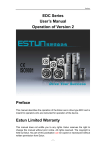
Figure 3.1 HSV-160B+-010A servo drive installation dimension
AC SERVO
SERIES
R
HSV -160B+-010
M S
AL
EN
COM
COMMAND
R
S
T
PE
ENCODER
U
V
W
PE
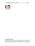
Figure 3.2 HSV-160B+-020/030A servo drive installation dimension
82
70
6
6
174
AC SERVO
SERIES
HSV-160B+-030
M S
190
ENCODER
U
V
W
PE
COMMAND
R
S
T
PE
1
2
EN
COM
178
AL
2-4.6
- 17 -
Chapter 3 Specification
Figure 3.3 HSV-160B+-050/075A servo drive installation dimension
AC SERVO
SERIES
R
HSV-160B+-050
M S
AL
EN
R
S
COM
T
PE
BK 2
COMMAND
BK 1
U
V
ENCODER
W
PE
3.2 Isolating transformer specification
HSV-160B+ AC servo drive uses 3-phase or single phase AC 220v power
supply. 3-phase 380/220v servo isolating transformer is recommended, and
the capacity of isolating transformer depends on the servo drive system
capacity. When you select the isolating transformer, it is necessary to take the
servo drive system capacity for each axis
into account comprehensively.
You can consider step by step in the following way:
1) Select suitable motors based on the mechanical load inertia, torque and
trasmission method adopted.
2) Select the servo drive type based on the selected motors.
3) Calculate the servo isolating transformer capacity based on the motor
technical datum.
Example: If a system adopts three HSV-160 B+ AC servo drives whose motor
powers are P1, P2, P3, the servo isolating transformer power must observe the
following formula:
- 18 -
Chapter 3 Specification
P0 >
(P1+P2+P3) * η
("η" is a conversion coefficient, and generally, adopts a value 0.6 to 0.8)
4)
Select the servo isolating transformer specification corresponds to the
calculated servo isolating transformer capacity.
- 19 -
Chapter 4 Installation
Chapter 4 Installation
4.1 Check on delivery
On receipt of products, users must check and confirm the following items:
Items to check
Content (for reference)
Whether the products are
Visual inspection to check whether the products
damaged or not
damaged or not during transportation
Whether the products are
Check the nameplates of servo drive units and
delivered in accordance with
servo motors
the indent or not
Whether the accessories are
Check the packing list and make sure that the
complete or not
accessory type and quantity is correct.
Whether the motor rotor can
Check and make sure that the motor rotor can be
be easily turned by hand
easily turned by hand, except motors with brakes.
Note: For the items mentioned above, if there's any problem, please feel free
to contact with the supplier or us.
Attention
�
Do not install servo drives and servo motors which are damaged
or with incomplete parts.
�
Use the specified combination of servo drives and servo motors.
�
Do not touch the motor rotor by hand directly, otherwise, it could
cause corrosion.
- 20 -
Chapter 4 Installation
4.2 Installation environment
�
Caution
�
�
�
The servo drive are supposed to be
installed in the well protected
switching cabinet to prevent dust,
corrosive gas, conductive foreign
bodies, fluids and inflammables from
entry.
The servo drives are supposed to be
installed in accordance with the
specified direction and side distance
to ensure good heat dissipation
conditions.
The servo drives and motors are
supposed to be free from vibration
and shock.
The servo drives are not supposed to
be installed near combustibles, in
order to avoid fire hazard.
4.2.1 Protection requirements
Structural protection are not specifically designed for the servo drives,
therefore, it is supposed to be installed in the well protected switching
cabinet to prevent corrosion, combustible gas, conductive foreign bodies,
metal powder, atomized oil and other fluids from entry of the servo drive .
4.2.2 Temperature requirements
�
Ambient temperature: 0℃ to 50℃
�
Safety long-time operating temperature: below 45℃
�
Ensure good heat dissipation.
4.2.3 Vibration and shock loading
Avoid vibration during servo drive installation, and adopt Vibration damping
measures to restrain the vibration below 0.5G (4.9m/S2). No vibration and
shock loading is permissible during servo drive installation.
4.3 Servo drive installation
Attention
�
Servo drives are supposed to be installed in the well protected electrical
cabinets.
- 21 -
Chapter 4 Installation
�
Servo drives are supposed to be installed in accordance with the specified
direction and distance to ensure good heat dissipation conditions.
�
The servo drives are not supposed to be installed adjacent to combustibles,
in order to avoid fire hazard.
4.3.1 Installation method
1) Installing the device
Adopt base plate installation method, and install the devie in a vertical
position. See Figure 4.1(4.2,4.3) for installing the device.
2) Installation spacing
Figure 4.4(4.6) shows the installing spacing for a solo servo drive and Figure
4.5(4.7) shows the installing spacing for multiple units. In actual installation,
keep the spacing as large as possible to ensure good heat dissipation
conditions.
3) Ventilation
In the electrical cabinet, airflow to the heat sink should be maintained to
ensure adequate cooling of the ambient temperature of the device.
- 22 -
Chapter 4 Installation
Figure 4.1 Schematic drawing of HSV-160B+-010 AC servo drive base plate mounting
Combination of bolts with
washer: M4×14
Standard:
GB/T9074.8-1988
Quantity: 4
- 23 -
Chapter 4 Installation
Figure 4.2 Schematic drawing of HSV-160B+-020/030 AC servo drive base plate
mounting
Combination of bolts
with washer: M4×14
Standard:
GB/T9074.8-1988
Quantity: 4
- 24 -
Chapter 4 Installation
Figure 4.3 Schematic drawing of HSV-160B+-050/075 AC servo drive base plate
mounting
Combination of bolts
with washer: M4×14
Standard:
GB/T9074.8-1988
Quantity: 4
- 25 -
Chapter 4 Installation
Figure 4.4 Installation spacing for a solo HSV-160B+-020/030 AC servo drive
AC SERVO
SERIES
R
M
HSV-160B+-050
S
AL
EN
R
S
COM
T
PE
BK 2
COMMAND
BK 1
U
V
ENCODER
W
PE
Figure 4.5 Installation spacing for the HSV-160B+-020/030 AC servo drive multiple
units
AC SERVO
M
AC SERVO
SERIES
SERIES
HSV-160B+-030
HSV-160B+-030
HSV-160B+-030
S
M
AL
S
M
AL
EN
1
2
- 26 -
R
S
T
PE
1
2
U
V
W
PE
EN
ENCODER
ENCODER
U
V
W
PE
AL
COMMAND
COMMAND
R
S
T
PE
S
COM
COM
ENCODER
U
V
W
PE
COMMAND
1
2
EN
COM
R
S
T
PE
AC SERVO
SERIES
Chapter 4 Installation
Figure 4.6 Installation spacing for a solo HSV-160B+-050/075 AC servo drive
AC SERVO
SERIES
R
M
HSV-160B+-050
S
AL
EN
R
S
COM
T
PE
COMMAND
BK 1
BK 2
U
V
ENCODER
W
PE
Figure 4.7 Installation spacing for the HSV-160B+-050/075 AC servo drive multiple
units
AC SERVO
AC SERVO
AC SERVO
SERIES
R
M
SERIES
R
HSV-160B+-050
S
M
AL
SERIES
R
HSV-160B+-050
S
M
EN
AL
HSV-160B+-050
S
EN
AL
S
T
T
T
PE
PE
BK 1
BK 2
U
U
U
V
V
V
PE
- 27 -
W
PE
ENCODER
W
ENCODER
PE
ENCODER
W
COMMAND
BK 2
COMMAND
BK 2
BK 1
COMMAND
BK 1
PE
COM
R
S
COM
R
S
COM
R
EN
Chapter 4 Installation
4.4 Installation of servo motors
Attention
�
To prevent the motor from vibration and impact, knocking on the motor
rotor or encoder is forbidden.
�
When transport the motor, you should not drag at the motor rotor, the
outlet wires, or the encoder.
�
Motor rotor cannot be overloaded, otherwise, the motor could be
damaged.
�
Make sure the motors are fastened, and take measures to avoid loose or
drop out.
4.4.1 Installation environment
1) Protection
If the servo motor is not waterproof type, you should prevent liquids splash
on the motor during installation and operation, especially avoid entry of
grease into the motor internal via lead wires or the motor rotor.
Note: If users demand for waterproof type servo motors, please declare in the
indent.
2) Temperature and relative humidity
Ambient temperature should be kept between 0 and 40 ℃ (No icing). The
motor temperature increases as the operating time last for long, therefore,
enforcing heat dissipation should be taken into account if the ambient space
is inadequate or other devices also heat the air. The relative humidity should
not be higher than 90% and no condensation.
3) Vibration
Avoid vibration for the servo motor installation. Vibration should be less
than 0.5G (4.9m/S2).
4.4.2 Servo motor installation method
1) Way of installation
GK6 motor series can be installed in a horizontal position or a vertical
- 28 -
Chapter 4 Installation
position.
2) Installation instructions:
�
When you assemble or disassemble the belt drive of the motor, do not
knock on the motor or rotor to avoid damage to the encoder. And use
helical drawing tools for thermal expansion joint assembly and
disassembly.
�
GK6 motors can't afford overload in the axial and radial direction.
Recommendation: Use resilient expansion joint to connect the loads.
�
When mounting the motors, you need to use spring plug to fasten the
bolts, and thereby avoid loose of drop-out.
- 29 -
Chapter 5 Wiring
Chapter 5 Wiring
Warning
�
Wiring and checking personnel must be qualified for this job.
�
Wait 5 minutes for wiring and checking after power off to avoid electric
shock.
Attention
�
Wiring is supposed to be done according to the terminal voltage and
polarity to avoid damage to the device and/or personal injuries.
�
The high frequency oscillated current flows through the servo motor, and
the leakage current will be heavy. Therefore, the servo motor earthing
terminal and the servo drive earthing terminal (PE) should be together
reliably grounded.
Attention
�
When assemble/disassemble the mechanical connection parts of the motor
rotor, do not use the hammer to knock on the rotor direclty, otherwise, the
motor encoder could be damaged.
�
Align the end faces of the motor rotor to the best condition,otherwise,
vibration could arise or the motor bearing could be damaged.
- 30 -
Chapter 5 Wiring
5.1 Standard wiring
The external connection of the servo drive depends on the selected control
mode.
5.1.1 Position control mode
For standard wiring (a) in the position control mode, see Figure 5.1; for
standard wiring (b), applicable to Siemens controller 801, in the position
control mode, see Figure 5.2.
5.1.2 Speed and torque control mode
For standard wiring in the speed and torque control mode, see Figure 5.3.
5.1.3 Conductor configuration
1) Mains terminals
�
Cross section of the wires for terminal R, S, T, PE, U, V, W ≥ 1.5 mm2
(AWG14-16).
�
Grounding: The cross section of the grounding wires should be as large
as possible. The servo drive and motor are supposed to be connected to
the PE terminal, and thereby grounded. Grounding resistor <4Ω.
�
Adopt UT1.5-4 cold pressed pre-insulated terminals. Make sure the
terminals are tightly connected.
�
It is recommended to use 3-phase isolating transformer for power supply,
in order to reduce the possibility of electric shock.
�
It is recommended to use mains filter before supply to reduce
interference.
�
Install No Fuse Breaker (NFB) to enable the power shutdown of the
external mains in the event of drive fault.
2) Command signals and encoder signals
�
Cross section of the wires: Use shielded cables (shielded cables with
twisted-pair are recommended). The cross section of the wires 0.12 ≥
mm2 (AWG24-26). The shielding is supposed to be connected with the
PE terminal.
�
Cable lengths: The cables should be as short as possible. Control cable
length ≤ 10 meters; feedback signal cable lenth ≤ 40 meters.
- 31 -
Chapter 5 Wiring
�
Wiring layout: The signal wirings should be kept away from the power
cables to prevent the entry of interference.
�
Install surge absorbers with inductive components (coils) for related
circuits. Freewheeling diodes are antiparallelly connected to the DC
coils, and RC absorbed circuits are parallelly connected to the AC coils.
Caution
�
U, V, W must be connected to the motor windings exactly in corresponding
order. Note that you can not adjust the positions of the three terminals to
make the motor run in the reverse direction. This is different from the
asynchronous motors.
�
Cables and lead wires are supposed to be fixed avoiding the heat sink of
the drive and the servo motor. Otherwise, the insulation property could be
reduced due to overtemperature.
�
There is large-capacity of electrolytic capacitance storing in the servo
drive, even after power removal, the voltage supply will remain high for a
period of time. Do not touch the servo drive or motor within 5 minutes
after power removal.
- 32 -
Chapter 5 Wiring
Figure 5.1Standard wiring (a) in the position control mode
AC
Servo Drive
交流伺服驱动器
/050/075
HSV
HSV--160
160BB-010/020/030
010/020/030/050/075
Golden age motor
登奇电机
Single phase
or 3-phase
单相或三相
R
S
T
PE
AC220V
NFB
MC
U
V
W
PE
COMMAND
position
command
位置指令
(plus) PLUS
位置指令
position
SIGN
command
(sign)
A+
AB+
BZ+
ZCP+
CPDIR+
DIRGD
GD
32
33
18
36
35
34
14
15
16
17
23
24
EN
1
A-CL
2
ENCODER
16,17
18,19
23,24
25
1
2
3
4
5
6
7
8
9
10
11
12
13
26
14,15
+24V ISO
�
�
�
�
�
�
�
�
�
�
Servo enable
伺服使能
报警清除
cleared
Alarm
Deviation
偏差计数器清零
counter clear
指令脉冲禁止
Command
pulse
CCW 驱动禁止
prohibition
CCW CW驱动禁止
drive
prohibition
CW drive
24V 电源地
prohibition
24v Mains
earthing
定位完成/速度到达
Target-position/
伺服准备好
Target-speed
achieve 伺服报警
Drive ready
Drive Alarm
M
3~
BK1
BK2
External外接制动电阻
braking
resistor
Encoder
signal
编码器信号
feedback
反馈
U
W
V
PE
CLEE
INH
L-CCW
3
4
5
L-CW
6
COM
COM
19
20
GET
7
READY
8
ALM
9
1
4
2
3
104 1N4148
2.7K
+24V ISO
1
4
2
3
104 1N4148
2.7K
+24V ISO
1
4
2
3
104 1N4148
2.7K
+5V
+5V
GND
GND
A+
AB+
BZ+
ZU+
UV+
VW+
WOH1
OH2
PE
12 +5V
13 GND
2 A+
3 A4 B+
5 B16 Z+
17 Z6 U+
7 U8 V+
9 V10 W+
11 W14 电机过热
motor
15 电机过热
1 PE
overheat
+24V ISO
1
4
2
3
104 1N4148
2.7K
+24V ISO
1
4
2
3
104 1N4148
2.7K
+24V ISO
1
4
2
3
104 1N4148
故障连锁端子
2.7K
4
3
2
1
- 33 -
READY
COM
MC1
MC2
�
Drive ready
伺服准备好
24V电源地
24v mains earthing
�
�故障连锁Fault interlock
�故障连锁Fault interlock
Chapter 5 Wiring
Figure 5.2 Standard wiring (b), applicable to Siemens controller 801
AC Servo drive
交流伺服驱动器
HSV
B-010/
020/030
/050/075
HSV--160
160B
010/020/030
020/030/050/075
Golden登奇电机
Age motor
Single or
单相或三相
3-phase AC
220vAC220V
NFB
R
S
T
PE
MC
External
braking
外接制动电阻
resistor
U
V
W
PE
PLUS
Position
位置指令
SIGN
Command
SIGN24V 电源地
Z
CP+(801)
CP-(801)
DIR+(801)
DIR-(801)
COM
21
26
25
29
30
19
EN
1
16,17 +5V
18,19 +5V
23,24 GND
25
GND
1
A+
2
A3
B+
4
B5
Z+
6
Z7
U+
8
U9
V+
10
V11
W+
12
W13
OH1
26
OH2
14,15 PE
+24V ISO
�
�
�
�
�
Drive enable
伺服使能
Alarm cleared
Deviation
报警清除
counter clear
Command pulse
偏差计数器清零
prohibition
Command pulse
指令脉冲禁止
prohibition
CCW drive
CCW 驱动禁止
prohibition
CW drive
CW 驱动禁止
prohibition
24v mains
earthing
24V 电源地
�
�
�
Target-position-ac
定位完成/速度到达
hieve/target-speed
-achieve 伺服准备好
Drive ready
伺服报警
Drive alarm
12
13
2
3
4
5
16
17
6
7
8
9
10
11
14
15
1
+5V
GND
A+
AB+
BZ+
ZU+
UV+
VW+
W电机过热
motor
电机过热
PE
ENCODER
24v mains
earthing
�
�
�
M
3~
BK1
BK2
COMMAND
Z pulse output
Position
Z 脉冲输出
command
PLUS 位置指令
U
W
V
PE
A-CL
2
1
4
2
3
104 1N4148
2.7K
+24V ISO
1
4
2
3
104 1N4148
2.7K
+24V ISO
CLEE
3
INH
4
L-CCW
5
1
4
2
3
104 1N4148
2.7K
+24V ISO
1
4
2
3
104 1N4148
2.7K
overheat
+24V ISO
1
4
2
3
104 1N4148
2.7K
+24V ISO
L-CW
6
1
4
2
3
104 1N4148
2.7K
Fault interlock terminals
故障连锁端子
COM
20
GET
7
READY
8
ALM
9
4
3
2
1
- 34 -
READY
COM
MC1
MC2
伺服准备好
�
Servo ready
24V
24v mains
� 电源地
故障连锁
earthing
故障连锁
�
�
Fault interlock
Fault interlock
Chapter 5 Wiring
Figure 5.3 Standard wiring in the speed and torque control mode
AC servo Drive
交流伺服驱动器
B-010/
020/030
/050/075
HSV
HSV--160
160B
010/020/030
020/030/050/075
Golden登奇电机
Age motor
R
S
T
PE
single or单相或三相
3-phase
AC 220v AC220V
NFB
MC
U
V
W
PE
COMMAND
Analogue
模拟电压指令
voltage
-10V~+10V
command
-10 to +10v
A+
AB+
BZ+
ZAN+
ANGN
GN
ENCODER
32
33
18
36
35
34
12
13
27
28
+24V ISO
�
�
�
�
�
�
�
�
�
�
Servo伺服使能
enable
Alarm cleared
报警清除
Deviation
counter
clear
偏差计数器清零
Command pulse
prohibition
指令脉冲禁止
CCW drive
CCW 驱动禁止
prohibition
CW drive
CW 驱动禁止
prohibition
24v mains
earthing
24V 电源地
Target-position
-achieve/
定位完成/速度到达
target-speed-ac
hieve
伺服准备好
Drive ready
Drive alarm
伺服报警
M
3~
BK1
BK2
External braking
外接制动电阻
resistor
Encoder
signal编码器信号
feedback反馈
U
W
V
PE
EN
A-CL
CLEE
INH
L-CCW
1
2
3
4
5
L-CW
6
COM
COM
19
20
GET
7
READY
8
ALM
9
1
4
2
3
104 1N4148
2.7K
+24V ISO
1
4
2
3
104 1N4148
2.7K
+24V ISO
1
4
2
3
104 1N4148
2.7K
16,17
18,19
23,24
25
1
2
3
4
5
6
7
8
9
10
11
12
13
26
14,15
+5V
+5V
GND
GND
A+
AB+
BZ+
ZU+
UV+
VW+
WOH1
OH2
PE
12
13
2
3
4
5
16
17
6
7
8
9
10
11
14
15
1
+5V
GND
A+
AB+
BZ+
ZU+
UV+
VW+
W电机过热
电机过热
PE
motor
overheat
+24V ISO
1
4
2
3
104 1N4148
2.7K
+24V ISO
1
4
2
3
104 1N4148
2.7K
+24V ISO
1
4
2
3
104 1N4148
Fault
interlock terminals
故障连锁端子
2.7K
4
3
2
1
- 35 -
READY
COM
MC1
MC2
伺服准备好
Drive ready
24V
24v电源地
mains earthing
故障连锁
Fault
interlock
故障连锁
Fault interlock
Chapter 5 Wiring
5.2 Signals and functions
5.2.1 HSV-160B+-010/020/030 AC servo drive terminal configuration
Figure 5.4 shows configuration of HSV-160B+-010/020/030 AC servo drive
interface terminals, including mains terminals, serial-port communication
terminals (COM), signal control socket (Command), encoder interface and
fault interlock terminals.
Figure 5.4 HSV-160B+-010/020/030 AC servo drive interface terminal configuration
Mains terminals
电源 端子
4
3
5
2
6
1
R
COM
S
36
19
T
PE
BK1
BK2
1
18
C OM MA ND
14
U
26
1
13
V
E NCODE R
W
PE
1
2
3
4
Fault故interlock
障 连 锁 端 子terminals
( 端 子 顺 序(The
是 驱 动terminal
安 装后 以
1-2-3-4is
外1-2-3-4
向 里为准 )
sequence
looking from the
external to the internal) after drive
installation.
- 36 -
Chapter 5 Wiring
5.2.2 HSV-160B+-050/075 AC servo drive terminal configuration
Figure 5.5 shows HSV-160B+-050/075 servo drive interface terminal
configuration,
including mains
terminals,
serial-port
communication
terminals (COM), control terminals (Command), encoder signal terminals
and fault interlock terminals.
AC SERVO
S E R IE S
R
M
H S V -1 6 0 B +-0 5 0
S
AL
EN
R
S
PE
BK 2
U
CO M M AND
BK 1
COM
T
V
PE
ENCO DER
W
4
1
MC
- 37 -
Chapter 5 Wiring
Figure 5.5 HSV-160B+-020/030 AC servo drive interface terminal configuration
Mains
terminals
电源端子
1
R
2
S
3
T
4
PE
5
BK1
6
BK2
7
U
8
V
9
W
10
PE
4
3
5
2
6
1
COM
36
19
1
18
COMMAND
14
26
1
13
ENCODER
1
2
3
4
故障连锁端子
Fault interlock terminals
(The terminal
sequence
is
1-2-3-4
looking
from
the external
(端子顺序是驱动安装后以
1-2-3-4
外向里 to
the internal
after
drive
installation)
为准)
- 38 -
Chapter 5 Wiring
Plugs, lugs and pins of the COMMAND and ENCODER sockets are shown
as follows:
Figure 5.6 Lugs and pins of the (Command) control terminals (looking in the face of the
lugs)
Figure 5.7 Plug of the control terminals (Command) (looking in the face of the plug)
Figure 5.8 Lugs of the encoder socket (looking in the face of the plug)
- 39 -
Chapter 5 Wiring
Figure 5.9 Plug of the encoder (looking in the face of the plug)
5.2.3 HSV-160B+-010 AC servo drive mains terminals
HSV-160B+ -010/020/030 mains terminals
Table 5.1
Terminal
No.
Terminal
Mark
1
R
Signal
Designation
Main circuit
power
(Single or
3-phase)
2
S
3
T
4
PE
5
BK1
System
grounding
External
braking
resistor
6
BK2
Terminal
No.
Terminal
Mark
1
U
2
V
3
W
Decription
Main circuit power input terminal
supply: AC220V/50Hz
Single phase power supply is not
recommended, which only can be
used in low power occasions.
Note:Do not connect the mains
input terminal with the motor
output terminal U, V, W.
Grounding terminal.
Grounding resistor <4Ω.
Motor output terminal and power
input terminal should share one
connection point.
The external and internal braking
resistor should be parallelly
connected. The internal braking
resistance is of HSV160B-030A is
200W 70Ω. For selection and
connection of the braking resistors
see the Annexure.
Warning: Do not short circuit
BK1 and BK2, otherwise, the
drive could be burnt.
Signal
Designation
Servo motor
output
- 40 -
Description
The servo motor output
terminals should be
connected with the
terminal U,V,W
correspondingly in the
right order.
Chapter 5 Wiring
4
PE
System
grounding
System
grounding
Grounding terminals.
Grounding resistance <4Ω
Servo motor output
terminal and power input
terminal should share one
connection point.
Grounding terminals.
Grounding resistance <4Ω
Servo motor output
terminal and power input
terminal should share one
connection point.
5.2.4 HSV-160B+ -050/075 mains terminals
Table 5.2 HSV-160B+ -050/075 mains terminals
Terminal
Terminal
Signal
No.
Mark
Designation
1
R
2
S
3
T
4
PE
Main circuit
power
(single phase or
three-phase)
Grounding
- 41 -
Description
Main circuit power input
terminal supply:
AC220V/50Hz
Single phase power
supply is not
recommended, which
only can be used in low
power occasions.
Note:Do not connect
the mains input
terminal with the
motor output terminal
U, V, W.
Grounding terminals.
Grounding resistance
<4Ω.
The servo motor output
terminal and power
input terminal should
share one connection
point.
Chapter 5 Wiring
5
BK1
6
BK2
7
U
8
V
9
W
10
PE
External braking
resistance
Servo motor
output
Grounding
Grounding
The external and
internal braking
resistance are supposed
to be connected
parallelly. The internal
braking resistance is
200w 7Ω. For selection
and connection of , see
the Annexure.
Warning: Do not short
circuit BK1 and BK2,
otherwise, the drive
could be burnt.
Servo motor output
terminals are supposed
to be connected with
terminal U, V, W
correspondingly in the
right order.
Grounding terminals.
Grounding resistance
<4Ω.
The servo motor output
terminal and power
input terminal should
share one connection
point.
Grounding terminals.
Grounding resistance
<4Ω.
The servo motor output
terminal and power
input terminal should
share one connection
point.
5.2.5 Serial-port communication interface (COM)
Table 5.3 Serial-port communication interface (COM)
Terminal
Terminal
Terminal
No.
Mark
Designation
2
TXD
Datum
receive
3
RXD
Datum
transmit
- 42 -
Description
This terminal should be
connected with the controller
or PC serial-port TXD to
realize serial-port
communication.
This terminal should be
connected with the controller
or PC serial-port RXD to
Chapter 5 Wiring
1, 5
realize serial-port
communication.
Data signal grounding
Signal
grounding
GND
If you want to use serial-port communication function, please contact our
after-sale service or development department for the communication
softwares. For connection of communication cables, see the drawing below:
PC
terminal
PCserial-port
机串口端子
Drive COM
terminal
驱动器
COM
端子
RXD
2
2
RXD
TXD
3
3
TXD
GND
5
1,5
GND
DB9 pins
DB9
头孔
Keypad
socket
键盘插座
5.2.6 Fault interlock terminals
Figure 5.4 Fault interlock terminals
Terminal
Terminal
Signal
No.
Mark
Designation
Drive ready for
4
READY
3
COM
24 V power input
2
MC1
Fault interlock
output
- 43 -
Description
Drive ready for terminal
output
SRDY ON: It indicates that
power supply is normal, no
alarm occurs, and the drive is
ready for the output of signal
"ON";
SRDY OFF: It indicates that no
power supply is available or
alarm occurs, so the drive is
ready for the output of signal
"OFF".
Power supply of the input
terminal is used to drive the
optical coupler
DC 24V, current ≥ 100mA
Fault interlock output
terminals output relay.
Chapter 5 Wiring
1
Relay connection breaks off in
the event of drive fault.
MC2
5.2.7 Control Signal terminals (COMMAND)
Table 5.5 Control terminals (COMMAND)
Terminal
Terminal
Signal
No.
Mark
Designation
1*
EN
Drive enable
signal
2*
A-CL
Alarm clear
signal
3*
CLEE
Deviation
counter clear
signal
4*
INH
Command
pulse
prohibition
signal
L-CCW
CCW servo
drive
prohibition
signal
5*
- 44 -
Description
Input terminal of drive
enable
EN ON: Servo drive
operating is permitted.
EN OFF: If the servo drive
shut off,operating stops,
the motor will be in the
free state.
Note 1:Before you change
the state from EN OFF to
EN ON, the motor should
be at a standstill.
Note 2: After tuning to
EN ON state, wait at
least 50ms to input
commands.
Note 3: You can shield
this signal via parameter
STA-6 or always keep the
switch "ON".
Input terminal of alarm
clear
ACL ON: System alarm
cleared
ACL OFF: Hold system
alarm
Input terminal of position
deviation counter clear
CLEE ON: In the position
control mode, position
deviation counter clear.
Input terminal of position
command pulse
prohibition
INH ON: Command pulse
input prohibition
INH OFF: Command pulse
input effect
Input terminal of L-CCW
(counter-clockwise direction)
drive prohibition
OFF: CCW drive permitted
ON: CCW drive prohibited
Chapter 5 Wiring
6*
L-CW
7*
GET
8*
READY
Note 1: This signal is
used in the event of
mechanical limit exceed.
In the switch-ON
condition, motor torque
outputs 0 in CCW
direction;
You can shield
Note 2:
2:You
this signal via parameter
STA-8 or always keep the
switch "OFF".
Input terminal of L-CW
(clock wise direction) drive
prohibition
OFF: CW drive is permitted
ON: CW drive is prohibited
Note 1:This signal is used
CW servo
for mechanical limit
drive
exceed. In the switch-ON
prohibition
condition, motor torque
signal
outputs 0 in CW
direction;
You can shield this
Note2:
Note2:You
signal via parameter
STA-9 or always keep the
switch "OFF".
Output terminal of
Target-position
-achieve
Target-position- If the position deviation
achieve output counter value is within the
signal
preset positioning area, the
target-position-achieve
terminal outputs signal
"ON".
Output terminal of
target-speed
Target-speed- -achieve
achieve output When the target-speed is
signal
reached or exceeded, this
terminal outputs signal
"On".
Output terminal of drive
ready
SRDY ON: Power supply
is normal, no alarm occurs,
and the drive is ready for
Drive ready for
the output of signal "ON"
output signal
SRDY OFF: No power
supply is available or
alarm occurs, so the drive
is ready for the output of
signal "OFF".
- 45 -
Chapter 5 Wiring
9*
ALM
10
Reserved
11
Reserved
12
AN+
13
AN-
14
CP+
15
CP-
16
DIR+
17
DIR-
32
A+
Drive alarm
output signal
Analog
input positive
signal
Output terminal of drive
alarm
ALM OFF: When no drive
alarm occurs, this terminal
will output "OFF".
ALM ON: When drive
alarm occurs, this terminal
will output "ON".
Analog input command
positive.Connect with PC
analogue command output
terminal
Analog input command
negative.
Analog
input negative
signal
Command pulse Input terminal of external
command pulses.
input signal
Note 1: Set pulse input
(PLUS mode) mode via parameter
PA22
① Command pulse +
Command pulse Sign mode.
input signal ② CCW/CW command
pulse mode.
(SIGN mode)
③ 2-phase command
pulse mode.
Encoder A+
phase output Servo motor encoder A+
phase output terminal
signal
Encoder A-
33
A-
phase output
signal
Servo motor encoder Aphase output terminal
Encoder B+
18
B+
phase output
signal
Servo motor encoder B+
phase output terminal
Encoder B36
B-
phase output
signal
Servo motor encoder Bphase output terminal
Encoder Z+
35
Z+
phase output
signal
- 46 -
Servo motor encoder Z+
phase output terminal
Chapter 5 Wiring
Encoder Z34
Z-
phase output
signal
Servo motor encoder Zphase output terminal
31
26
Reserved
25
Reserved
29
Reserved
30
Reserved
27,28
GN
23,24
GD
21,22
Z
19,20
COM
Analog signal
ground
Mains output "-"
signal
Z pulse output
signal
Power input
signal ground
Analog signal ground
terminal
Control circuit reference
ground
Encoder Z pulse output to
Siemens 801 System
Power ground of the input
terminal.
It is used to drive the
optoelectronic coupler of
the input terminal.
DC24V power ground,
current ≥ 100 mA
5.2.8 Encoder signal terminals
Table 5.6 Encoder signal terminals
Terminal
Terminal
Signal
No.
Mark
Designation
1
A+
Encoder A+ input
2
A-
Encoder A- input
3
B+
Encoder B+ input
4
B-
Encoder B- input
5
Z+
Encoder Z+ input
6
Z-
Encoder Z- input
- 47 -
Description
Connect with servo
motor optical encoder
A+
Connect with servo
motor photoelectric
encoder AConnect with servo
motor photoelectric
encoder B+
Connect with servo
motor photoelectric
encoder BConnect with servo
motor photoelectric
encoder Z+
Connect with servo
motor photoelectric
encoder Z-
Chapter 5 Wiring
7
U+
Encoder U+ input
8
U-
Encoder U- input
9
V+
Encoder V+ input
10
V-
Encoder V- input
11
W+
Encoder W+ input
12
W-
Encoder W- input
13
OH1
Thermal resistor
26
OH2
Thermal resistor
20, 21,
22
5V2
Encoder power
feedback
16, 17,
18, 19
+5V
Power output "+"
23,24,
25
GND
Power output "-"
14,15
PE
Shielding layer
Connect with servo
motor photoelectric
encoder U+
Connect with servo
motor photoelectric
encoder UConnect with servo
motor photoelectric
encoder V+
Connect with servo
motor photoelectric
encoder VConnect with servo
motor photoelectric
encoder W+
Connect with servo
motor photoelectric
encoder WServo motor thermal
resistor output
Encoder power
feedback, the servo
drive automatically
performs voltage
compensation
according to the
encoder power.
Servo motor
photoelectric encoder
uses +5 V power;
If the cable is long,
you should use
multiple cables to
connect parallelly
Connect with the servo
motor external shell
Note:
1) Control signal terminals No.1 to No.6 are used to specify input terminal
signals. The details can be defined via parameter
to
. Table 5.5 shows the default definition of the terminal signal.
2) Control signal terminals No. 7 to 9 are used to specify terminal output
signals. The details can be defined via parameter
to
. Table 5.5 shows the default definition of the terminal signal.
3) You can customize the Input/Output signal of the control signal
terminals, either "low level access" or "high level access". If the
- 48 -
Chapter 5 Wiring
corresponding PB parameter is positive, it indicates "low level access";
If it is negative, it indicates " high level access". See 7.3 Expansion
parameter mode for details.
5.3 Interface circuit
5.3.1 Switch value input interface
Figure 5.10 Switch value input interface
PC device
上位装置
Servo
drive
伺服驱动器
+24V
+24V
2.7k 2.7k
104
GND
GND
1) Power supply from servo drive internal is DC 24 V, current ≥ 100
mA.
2) Pin 19 and 20 pins of the control terminal should be duly connected
with the PC 24 V ground.
Note: Incorrect connection of 24 V ground will result in the abnormal
function of the servo drive.
5.3.2 Switch value output interface
- 49 -
Chapter 5 Wiring
Figure 5.11 Switch value output interface
上位装置
PC device
Servo伺服驱动器
drive
+24V
20Ω
max50mA
24VG
A: Relay connection
上位装置
PC device
+5V
伺服驱动器
Servo
drive
+24V
max50mA
20Ω
GND
24VG
B: Optoelectronic coupler connection
1) The external power supply DC 24V should be provided by users. Note:
If you invert the connection of power polarities, the servo drive could be
damaged.
2) Output uses open collector circuit form. The max. current is 50 mA and
the external power supply is DC 24V. Therefore, switch value output
signal load should observe the limit. Exceeding the limit or connecting
the output with the mains directly will result in damage of the servo
drive.
3) If you use relay like inductive load, the freewheeling diodes should be
connected with the load at both ends in inverted parallel. If the
freewheeling diodes connect reversely, the servo drive could be
damaged.
5.3.3 Pulse array input interface
- 50 -
Chapter 5 Wiring
Figure 5.12 Differential drive mode of pulse input interface
PC 上位装置
device
Servo伺服驱动器
drive
CP+
100Ω
Ω
CP-
100Ω
DIR+
100Ω
DIR-
100Ω
Ω
Ω
Ω
Figure5.13 Single-ended drive mode of pulse input interface
Servo
drive
PC
上位装置
伺服驱动器
VCC
R
CP+
100Ω
CP-
100Ω
Ω
Ω
R
DIR+
100Ω
DIR-
100Ω
Ω
Ω
1) In order to send the pulse data correctly, it is suggested to select
differential drive mode for the input interface. (especially when the
signal wires are long).
2) In the differential drive mode, use AM26LS31 or RS422 line to drive.
3) Single-ended drive mode will lower the action frequency. As pulses
input in the circuit, the drive current varies between 10 and 15 mA. The
max. external voltage supply should not be greater than 25 V, based on
- 51 -
Chapter 5 Wiring
which, we can calculate the value of the resistance.
Data summarised via our experience (for your reference):
VCC=24 V, R=1.3 to 2 k
VCC=12V, R=510 to 820Ω
VCC=5V, R=82 to 120Ω
4) Adopt single-ended drive mode, the external power should be provided
by the users. Note: If you invert the connection of power polarities, the
servo drive could be damaged.
5.3.4 Servo motor photoelectric encoder input interface
Figure 5.14 Servo motor photoelectric encoder input interface
+5V
10K
10K
A+
(B+、Z+ )
+
A(B、Z)
100Ω
A(B-、 Z-)
5.3.5 Analog command input interface
Figure 5.15 Analog command input interface
a: Analog differential input interface
Servo drive
PC上位装置
伺服驱动器
AN+
+
50K
AN CMD
+
-
AN-
50K
-
GN
10K
b: Analog single-ended input interface
- 52 -
Chapter 5 Wiring
PC
Servo drive
上位装置
伺服驱动器
AN+
+
50K
AN CMD
+
-
AN-
50K
-
GN
10K
1) If the analog input interface adopts differential mode, weather to use
differential input interface or single-ended input interface depends on the
connecting methods. The resistor is 765 KΩ and the input voltage supply
range from -10 V to + 10 V or 0 V to + 10V.
2) In the differential connection mode, the analog grounding wire and the
input terminal negative should be connected at the controller side.
Besides, three wires are required for the connection of controller and the
servo drive.
3) In the single-ended mode, the analog grounding wire and the input
terminal negative should be connected at the controller side. Besides,
two wires are required for the connection of the controller and the servo
drive.
4) Differential connection mode excels single-ended connection mode,
since it can inhibit interference of common mode.
5) The input voltage supply can not exceed the range: -10 V to +10 V,
otherwise, the drive could be damaged.
6) It is suggested to use shielding cables for connection in order to reduce
noise interference.
7) Existing of zero drift at the analog input interface is normal, but zero
drift compensation can be made via adjusting parameter PA8.
8) The analog interface is not isolated (non-insulated).
5.3.6 Analog command output interface
Figure 5.16 Analog command output interface
- 53 -
Chapter 5 Wiring
5.3.7 Position feedback signal output interface
Figure 5.17 Position feedback signal output interface (a)
Servo drive
伺服驱动器
PC device
上位装置
A+
A
A-
B+
B
B-
Z+
Z
ZAM26LS31
AM26LS32
GND
Figure 5.18 Position feedback signal output interface (b)
Servo drive
伺服驱动器
PC device
上位装置
220Ω
A+
A
IN 4 1 4 8
A-
220Ω
B+
B
IN 4 1 4 8
B-
220Ω
Z+
Z
IN 4 1 4 8
Z-
6N137
A M 2 6 LS 3 1
- 54 -
Chapter 5 Wiring
1) Encoder position feedback signals output via differential drive
AM26LS31.
2) Controller input interface may use AM26LS32 receiver, which is
supposed to be connected with the terminal resistor about 330Ω.
3) The controller grounding wires should be reliably connected with the
servo drive grounding wires.
4) Non-isolated output.
5) The controller input interface may also use photoelectric coupler for
receipt, however, it is supposed to be the high speed photoelectric
coupler like 6N137.
5.3.8 Open collector output interface for the encoder Z-phase signal
6) The encoder Z-phase signal outputs via open collector. When the
encoder Z-phase signal arises, it outputs "ON" signal to conduct the
access, otherwise, it outputs "OFF" signal to stop the access.
7) Non-isolated output ( not insulated).
8) In PC, the width of the Z-phase signal pulse is normally narrow,
therefore, you should use high speed photoelectric coupler receiver like
6N137.
Figure 5.19 Open collector output interface for the encoder Z-phase signal
Servo
drive
伺服驱动器
PC
上 位device
装置
+ 5V
m ax 2 5 V
m ax 5 0 m A
Z
Z
C OM
GND
- 55 -
Chapter 6 Operation and Display
Chapter 6 Operation and Display
pad operation and display
6.1 Key
Keypad
�
Figure 6.1 shows the panel.
Figure 6.1 HSV-160B+-010/020/030/50/075A AC Servo drive panel
�,�
�, �, M,
The drive panel comprises 6 LED segment displays and 5 keys (�
S), which are used to show various status of the system and parameter
settings etc. Functions of the keys:
M: Mode changing in the main menu category
S: Entry of the submenu, or return, or input saving
▲: Increase in serial number or value, or forward to the next option
▼: Decrease in serial number or value, or back to the previous option
: Replacement
�
After connecting the drive power, the 6 LED segment will appear on the
display.
�
Users are supposed to operate on the multi-level menus. The first-level
menu is the main menu which includes five operation modes. In each
operation mode, there's a function submenu. Figure 6.2 shows the main
menu diagram:
- 56 -
Chapter 6 Operation and Display
Figure 6.2 HSV-160B+ Series servo drive main menu
Status display mode
Motion parameter mode
Press
M
Press S
Submenu
Expansion parameter mode
Press S
Auxiliary function mode
Status control mode
�
Press M to change the operation mode in the main menu. Via pressing
�,�, you can enter the function submenu.
�
Select
in the main menu, press �,�to enter the display
mode. HSV-160B+ AC servo drive has 19 displays (see table 6.1). Users
can select the required display usage via pressing �,�and then press S
to observe the status information of the servo drive in the selected
display mode. To quit the selected display mode, press S again; To
return to the main menu, press M.
- 57 -
Chapter 6 Operation and Display
Figure 6.3 Status monitoring mode menu and demonstrations
Position deviation: -634 pulses
S
Actual speed: -463 r/min
Display of motor torque (Unit:
0.1%)
Target position command pulses:
1436875
Actual feedback position pulses:
1436875
Position command input
frequency: 75 Kpps
Target speed command: -463
r/min
Display of motor current: 1.2 A
Alarm code. "0": No alarm
reported.
Input interface status
Output interface status
U-phase momentary current
feedback
Current position of motor
magnetic pole
Motor absolute position
mechanical angle
Pumping braking load ratio
Motor actual load ratio in the
past 10s.
S
Reserved
- 58 -
Chapter 6 Operation and Display
Table 6.1 Display modes list
S.N.
Segment Display
Description
1
Display of position tracking error (Unit: pulse)
2
Display of actual speed (Unit: 1r/min)
3
Display of motor torque (Unit: 0.1%)
4
Display of position specified 4 bits (low)
5
Display of position specified 4 bits (high)
6
Display of position feedback 4 bits (low);
7
Display of position feedback 4 bits (high)
8
Display of position command input frequency:
(Unit: 0.1 Kpps);
9
Display of speed command (Unit: r /min);
10
Display of motor current (Unit:0.1A);
11
Display of alarm interface status;
12
Display of input interface status;
13
Display of output interface status;
14
Display of U-phase current feedback (Unit: digital,
"32767" indicates the max. positive current);
15
Display of motor magnetic pole position;
16
Display of motor absolute position mechanical
angle;
17
Display of pumping braking load ratio (Unit: %)
18
Display of motor actual load ratio in the past 10s
(Unit: %)
19
Reserved
Note:
1) When the motor operates in the clockwise direction (reverse),
displays decimal; when the motor operates in the counter
clockwise direction,
2) If the display of
displays integer.
increases 10000, then the display of
- 59 -
Chapter 6 Operation and Display
will increase 1.
3) If the display of
increases 10000, then the display of
will increase 1.
4)
displays the command frequency, unit: 0.1 KPPS. For
example, the century star triggers pulses,
displays 840,
value can be calculated by the following formula:
(840 × 0.1 × 1000 × 60) / 10000 = 840 × 0.1 × 6 = 84 × 6 = 504
5)
displays speed command, unit: r/min. For example,
=100,
6)
will display 10 (when
= 0).
displays hardware alarm interface status. When the lamp
(alarm indicator) on the panel is red, it means a servo drive hardware
alarm is reported. Alarms can be reported via this monitoring display, for
example
. After trouble shooting and fault clearance, the
servo drive system can be recovered via alarm reset function in the
auxiliary mode or servo drive powerdown recovery.
7)
displays the input interface status. It shows the input voltage
situations of the 6 pins, DIN1 to DIN6. For example, if the DIN1 input
voltage value = 24v (the input optical coupler is disconnect), the
corresponding segment displays lower parts blink; If the input voltage
value = 0v( the input optical coupler is connected), the corresponding
segment displays upper parts blink.
- 60 -
Chapter 6 Operation and Display
Figure 6.4 Indication of the input interface status
Bits:
Status
high level(1): lower
part blinks;
low level(0): upper
part blinks
Note:
�
High level (1) indicates the voltage value with which the optical coupler
cannot be connected. Generally, it is 24v;
�
Low level (0) indicates the voltage value with which the optical coupler
can be connected. Generally, it is 0v;
�
Input of which voltage value can effect the function depends on the
value of the 6 parameters,
to
. If the parameter
set values are positive, the function effects when input 0v; If the set
parameter set values are negative, the function effects when input 24v.
As for DIN1 to DIN6 represent which function, it depends on the
absolute values of the parameters
8)
to
.
indicates output interface status. When the corresponding
output function performs, the upper part of the digital segment displays.
Input of which voltage can effect the function depends on the pos. or neg.
of the set values of the parameters PB21 to PB23.
- 61 -
Chapter 6 Operation and Display
Figure 6.5 Indication of input interface status
Bits:
Status
ON: upper part blinks;
OFF: lower part blinks
9)
displays motor magnetic pole position. When the motor
operates counter clockwise at low speed, it blinks 3-1-5-4-6-2 sequential
numbers in turn; when the motor operates clockwise at low speed, it
blinks 2-6-4-5-1-3 invert sequential numbers in turn.
�
in the main menu, and then press �,� to
You can select
enter the motion parameter mode. HSV-160B+ AC servo drive has in
total 44 motion parameters.
Figure 6.6 Motion parameter mode menu
Press�
press M
�
Select parameter
value to
in the motion parameters and set its
, and then you may enter expansion parameter mode.
HSV-160B+ AC servo drive has 28 expansion parameters (including 2
reserved parameters).
- 62 -
Chapter 6 Operation and Display
Figure 6.7 I/O parameter setting mode menu
Press�
Press M
�
in the main menu, and then press �,� to
You can select
enter the auxiliary mode. HSV-160B+ has 7 auxiliary operation functions,
see Table 6.2)
Figure 6.8 Auxiliary operation mode menu
Press�
Press M
Table 6.2 Auxiliary mode list
Display
Mode
Function
Control parameter
saving
JOG operation
mode
Save the preset drive control
parameters to EEPROM
Drive and motor operate at the preset
speed in the JOG mode
Alarm reset mode
Drive reset, clear the history faults
- 63 -
Chapter 6 Operation and Display
Drive internal open loop testing
(Note: This mode is not applicable to
long time operation)
Parameter defaults All PA parameters reset to factory
recovery
default values
Calibrate the
Calibrate the motor encoder 0
encoder 0 position position
Parameter
Autotuning drive parameters to match
autotuning
with the motor load inertia
Internal testing
mode
�
in the main menu, and then press � , � to
You can select
enter the control parameter mode. HSV-160B+ AC servo drive has 16
control parameters including 6 reserved parameters.
Figure 6.9 Control parameter mode menu
Press
Press M
�
6-bit LED segment displays various status and datum of the servo drive
system. When "A" appears at the first bit, it indicates an alarm is
reported, and the rest segment indicates the alarm number.
Figure 6.7 Alarm display
�
After trouble shooting and fault clearance, the servo drive system can be
recovered via alarm reset function in the auxiliary mode or servo drive
powerdown recovery.
6.2 Parameter management
�
Attention
After parameter revision, you should select "EE-WRI" in the
auxiliary mode, and then press S to activate the revised parameter.
� Parameter setting takes effect immediately, so wrong setting could
- 64 -
Chapter 6 Operation and Display
result in unexpected actions of the device or even accidents.
6.2.1. Parameter change and saving
1)
Motor and drive code & expansion parameter changing and saving
To change the paramter
and the expansion parameters from
to
, select
press � , � to select
in the first layer, and then
. Press S, the parameter value is displayed.
Press � , � to change the parameter value. Pressing � or � once, the
parameter value changes 1; Keep pressing � or � , the parameter value
changes continuously. Press � , the modifying position moves one bit left
(left cycle). When you change the parameter, the LED display right end
decimal point is bright. If you set
=
, you can change
via operating ditto. Press M to switch to
the value of the parameter
expansion parameter
, and you can modify expansion parameters
via operating ditto; Otherwise, press S to return to parameter selection menu
without effecting. To save the parameter modification or setting, first you
need to input the password
to the parameter
then press M to switch to
, and
mode. Press S to save the
modification or set value to the drive EEPROM. After saving complete, the
segment displays
; Or if it fails, the segment displays
.
Press M, you can switch to other modes; Or press �, � to change the motion
parameters.
2) Modifying and saving motion parameters
To modify and save the control parameters:
to
parameter
,
to
to
. First, select
to
,
, and control status
in the first layer,
press � , � to select the parameter number. Press S to view the parameter
� to change the parameter value. Press � or � once, the
value. Press � 、�
- 65 -
Chapter 6 Operation and Display
parameter value changes 1; Keep pressing � or � , the parameter value
changes continuously. Press � , the modifiying position moves one bit left
(left cycle). When you change the parameter, the LED display right end
decimal point is bright. And then you can change the parameter via operating
ditto. Press S to return to the parameter selection menu without effecting. To
save the parameter modification or setting, first you need to input the
password
, and then press M to
to the parameter
mode. Press S to save the modification or set value to
switch to
the drive EEPROM. After saving complete, the segment displays
;
. Press M, you can switch to
Or if it fails, the segment displays
other modes; Or press �, � to change the motion parameters.
6.2.2. Parameter recovery
Press M to switch to
mode, select
and press � , � to select the parameter
displays
in the first layer,
. Press S, the segment
.The parameter recovery is completed. However, it takes
effect only after saving. Press S again, and then press M to switch to
. Press � or � to select the parameter, and set or change its value.
Press S to return to the parameter without effecting.
To save the parameter modification or setting, first you need to input the
password
switch to
to the parameter
, and then press M to
mode. Press S to save the modification or set value to
the drive EEPROM. After saving complete, the segment displays
.
Parameter recovery saving is complete. Reconnect the power supply after
powerdown, the parameters will recover to defaults. If the saving fails, the
segment displays
. Parameter recovery saving fails. Reconnect
the power supply after powerdown, the parameters can not recover to
defaults.
Parameter defaults depend on the servo motor brands selected. Now we use
- 66 -
Chapter 6 Operation and Display
Huada servo motors and Golden servo motors. The servo motor brand can be
told via the kilobit value of the parameter
. If you use Huada
servo motors, the parameters recover to Huada motor parameter defaults; If
you use Golden servo motors, the parameters recover to Golden motor
parameter defaults.
- 67 -
Chapter 7 Parameter Setting
Chapter 7 Parameter Setting
�
Attention
The technical persons who attend parameter adjustment should
understand the indications of the parameters. Wrong setting could
result in damages and/or injuries.
�
Suggestion: After parameter adjustment, first carry out the free-load
test run of the motor.
7.1 Function menu
HSV-160 B+ has various parameters, with which you can adjust or set the
drive performance and functions. In this chapter, it describes the usages and
functions of various parameters. It is crucial to master the optimal use of the
parameters and the operation of the drive.
HSV-160B+ parameters can be divided into three categories: First, motion
parameters; Second, expansion parameters; Third, control parameters. These
three categories respectively corresponding to the three parameter modes,
namely, motion parameter mode, expansion parameter mode and control
parameter mode. And the parameters can be checked, set and adjusted via
drive panel keys or computer serial ports.
Table 7.1 Explanation of parameter categorizing
Category
Motion
parameter
mode
Expansion
parameter
mode
Control
parameter
mode
Display
Parameter
Brief
No.
Description
0 to 43
You can ajust various characteristics,
set control operation methods and
motor related parameters.
0 to 23
You can set the second gain, the
third gain, and the I/O interface
function etc.
0 to 15
You can select alarm shielding
function or selection methods of
internal control function etc.
7.2 Motion parameter mode
HSV-160 B+ type servo drive has 44 motion parameters (thereof, 1 is
- 68 -
Chapter 7 Parameter Setting
reserved). The definitions are as follows:
�
Table 7.2 shows the drive factory defaults when it is in combination with
Golden Age motor GK 6060-6 (3 Nm, 2000 rpm). If combined with
other motor type, the usage and value of the parameters marked with "*"
may be different.
�
In the column "control modes applicable": "P" stands for position
control mode; "S" stands for speed control mode; "T" stands for torque
control mode.
Table 7.2 Motion parameter list
Parameter
No.
0
1
2
3
4
5
6
7
8
9
Name of the
Parameter
Position
loop
proportional
gain
Position
loop
feedforward
gain
Velocity
loop
proportional
gain
Velocity
loop
integral time
constant
Velocity
feedback filter
factor
Max. torque
output value
Acceleration
time constant
Velocity
command input
gain
Velocity
command zero
drift
compensation
Torque
command input
gain
Control
modes
applicable
Range
of
parameter
value
Factory
defaults
Unit
P
20 to 10000
400*
0.1Hz
P
0 to
150
0
%
P, S
200 to
20000
2500*
P, S
5 to 500
20*
P, S
0 to 7
0
P, S, T
30 to 500
250
1%
P, S
1 to 32000
200
ms
S
1 to 9000
2000
S
-1023
to 1023
T
- 69 -
1 to 300
ms
0
200
1%
Chapter 7 Parameter Setting
Torque
command zero
drift
compensation
Range
of positioning
completion
Range of
positioning
out-of-tolerance
T
-1023 to
1023
0
P
0 to 32767
20
Pulse
P
1 to 32767
20000
Pulse
13
Position
command pulse
numerator
frequency
P
1 to 32767
1
14
Position
command pulse
denominator
frequency
P
1 to 32767
1
P, S, T
0 to 500
250
1%
P, S, T
-500 to 0
-250
1%
P, S, T
100 to
12000
2500
1 r/min
10
11
12
15
16
17
Max. torque
output value in
the positive
direction
Max. torque
output value in
the negative
direction
Max.
velocity limit
18
System
overload torque
setting
P, S, T
10 to 120
120
0.1 %
19
Software
overtemperature
time setting
P, S
40 to 32000
4000
1 ms
20
Internal speed
S
-32000 to
32000
0
0.1 r/min
21
JOG mode
operation
P, S
0 to 2000
300
1
r/min
22
Position
command
pulse input
method5)
P
0 to 2
1
23
Control method
selection4)
P, S, T
0 to 3
0
- 70 -
Chapter 7 Parameter Setting
24
25
26
27
28
29
30
31
32
33
Servo
motor magnetic
pole
logarithm3)
Encoder
resolution2)
Encoder
zero position
offset1)
Current
control
proportional
gain
Current
control integral
time
The second
position
command pulse
numerator
frequency
The third
position
command pulse
numerator
frequency
P, S, T
1 to 4
3
P, S, T
0 to 3
2
P, S, T
-32767 to
32767
150
P, S
10 to 32767
2500
P, S
1 to 2047
45
P
1 to 32767
1
P
1 to 32767
1
P, S
0 to 500
1
0.1 ms
P, S
0 to 3000
0
1 ms
Pulse
0.1 ms/unit
Reserved
Torque
command filter
time constant
Position
feedforward
filter time
constant
34
Software
version/user's
password
P, S
0 to 2806
100
1. Password
for modifying
expansion
parameters or
motor related
parameters:
2003.
2. Password
for
parameter
saving:
1230.
35
Position
command for
smoothing
filter
time
P
0 to 3000
0
1 ms
- 71 -
Chapter 7 Parameter Setting
36
Communication
baud rate
37
Axis address
38
39
40
41
42
43
Deceleration
time constant
The fourth
position
command pulse
numerator
frequncy
Brake output
delay
Velocity
threshold
allowed for
brake output
Range of
target-speedachieve
Drive type code
0 to 3
2
P, S
1 to 15
1
S
1 to 32000
200
P
1 to 32767
1
P, S
10 to 2000
200
Unit: ms
P, S
10 to 300
100
Unit:
1rpm
P, S
1 to 500
10
Unit:
1rpm
2206
Kilobit: "1"
indicates
"Huada
motor";
"2"indicates
"Golen Age
motor";
Hundred bit:
"0" = 10A
"1" = 20A
"2" = 30A
"3" = 50A
"4" = 75A
"5" = 100A
tens place
and units
order
indicate the
motor type.
P, S
1000 to
2550
ms
Note:
To enable the parameters marked with 1), 2), 3), 4), 5) after changing, you
should save the changes first and then restart. To enable other parameters,
you can direct make changes on-line. However, the changes can not be
automatically saved.
7.2.1 Elaborate on motion parameter
Table 7.3 Parameter function list
S.N
.
Parameter
Name
0
Position loop
proportional
gain
Function
① Set position controller proportional gains
② The gain and rigidity increase as the set
- 72 -
Default
Range
of the
parameter
400
20 to
10000
Unit:
Chapter 7 Parameter Setting
1
Position loop
feedforward
gain
2
Velocity loop
proportional
gain
3
Velocity loop
integral time
constant
4
Speed
feedback filter
factor
5
Max. output
torque
percentage
setting
value increases, and in the same frequency
command pulse condition, the position lag is
less. But if the set value is too great, the
oscillation or overshooting may arise.
③Parameter values depend on the drive type
and load conditions.
①Set position loop feedforward gain.
②When set 100%, it indicates the position lag
is zero in any command pulse frequency
condition.
③As the position loop feedforward gain
increases, the position controller response
speed enhances, but the oscillation may occur
easily.
④When no fast response characteristic is
required, the parameter value is normally set to
0.
①Set the velocity controller proportional gain.
②The gain and rigidity increase as the set
value increases. The parameter values depend
on the drive system type and load conditions. In
general, the set value should increase as the
load inertia increases.
③Set a great value as possible, provided no
oscillation of the system occurs.
①Set velocity controller integral time constant.
②The integral speed increases as the set value
decreases. The parameter values depend on the
drive system type and load conditions. In
general, the set value should increase as the
load inertia increases.
③Set a small value as possible, provided no
oscillation of the system occurs.
①Set speed feedback low pass characteristic.
②As the set value increases, the cut-off
frequency lowers, and the motor noise
decreases. If the load inertia is great, the set
value can be duly reduced. If the set value is
too great, the response slows down and the
oscillation could arise.
③As the set value reduces, the cut-off
frequency increases, and the response speed
enhances. If high speed response is required,
the set value can be duly reduced.
①Set the internal torque limit of the servo
motor.
②The set value is the max. permissible
nominal input current of the motor.
③Whensoever, the limit is valid.
④"30 to 500" indicates the set range: 30 % to
500 % of the drive's max. output current.
Max. output torque = IRmotor*PA5
Thereof, IRmotor indicates the motor nominal
current (expansion parameter PB24). In
general, you can select Max. output current =
3*IR. Unit of parameter PA5: 1%.
- 73 -
0.1 Hz
0
0 to 150
indicates
the range
0 to 150 %
20000
200 to
20000
5
5 to 500
mS
0
0 to 9
300
30
to 500
Chapter 7 Parameter Setting
6
7
8
9
10
11
12
①The set value indicates the acceleration time
required by the motor to speed up from 0 to
Acceleration
2000 r/min.
time constant
②The characteristic of acceleration and
deceleration is linear.
①Set the relation between analog speed
command voltage and rotary speed.
Velocity
The set value indicates the corresponding
command
rotary speed when the voltage supply is +10V.
input gain
(Unit: 1 r/min)
②It is available only under analog speed input
mode.
In the analog speed control mode, via this
parameter, you can adjust the analog speed
Velocity
command input zero drift. Adjusting methods
command zero are as follows:
drift
① Shorting the analog control input terminal
compensation
and the signal ground terminal.
②Set the parameter value to stop the motor.
①Set the relation between analog torque
command voltage and the torque. The set value
indicates the corresponding torque when the
Torque
voltage supply is +10 V.
command
②It is available only in the analog torque input
input gain
mode.
③"0 to 300" indicates the range: 0 to 300% of
the drive's max. ouput current.
In the torque control mode, use this parameter
to adjust the analog torque command input zero
Torque
drift. The adjusting methods are as follows:
command
①Shorting the analog control input terminal
zero drift
compensation
and the signal ground terminal.
②Set this parameter value to stop the motor.
①Set pulse range of positioning completion in
the position control mode.
②This parameter provides a basis for the drive
to judge whether positioning is completed or
not in the position control mode. If the
Range of
remaining pulse quantity displays on the
positioning
position deviation counter is not greater than
completion
the set value, the drive takes it as positioning
completed. The positioning complete switch
outputs signal "ON"; Otherwise, it outputs
signal "OFF".
③In the position control mode, it outputs
positioning completion signal.
①Set the positioning deviation
Positioning
out-of-tolerance.
deviation
②In the position control mode, if the display of
out-of-tolerance the positioning deviation counter excelled this
detection range parameter value, the alarm of positioning
deviation out-of-tolerance is reported.
- 74 -
200
1 to 32000 ms
2000
0 to 9000
0
-1023 to
1023
200
10 to 300
0
-1024 to
1023
20
0 to 30000
Pulses
20000
1 to 32767
Pulses
Chapter 7 Parameter Setting
13
Position
command
pulse
numerator
frequency
①Set the position command pulse
fractional-octave-band. (electronic gear)
②In the position control mode, via setting the
parameter No.13 and No. 14, the device can be
matched with various pulse types, and the
optimal control resolution (angle/pulses) can be
achieved.
③ P×G=N×C×4
P: Input command pulses;
G: Electronic gear ratio
G= Frequency division numerator/ frequency
division denominator
N: Number of turns of the motor
C: Photoelectricity encoder winding/round,
for this system
C=2500
④ For example, if the input command pulse is
6000, the servo motor rotates per revolution.
Set the value of parameter No.13 = 5, and No.
14 = 3.
G=
1
1 to 32767
1
1 to 32767
N ×C ×4 1×2500×4 5
=
=
P
6000
3
⑤The recommended range for the electronic
gear ratio should be: 1 ≤ G ≤ 50
50
14
Position
command
pulse
denominator
frequency
15
CCW torque
limit
16
CW torque
limit
① See the parameter No. 13
①Set the internal torque limit of the servo
motor in the CW direction.
②The set value is the max. input current of the
servo motor.
③If the set value excels the max. output torque
permitted by the system, the actual torque limit
should be the max. output torque permitted by
the system.
④"0 to 500" corresponds to the range "0 to 250
500%" of the drive max. output current in the
positive direction.
CCW torque max. output current =
IRmotor*PA15
Thereof, IRmotor indicates the motor nominal
current (expansion parameter PB24). In general,
the max. output current in the pos. direction = 3 *
IRmotor. The unit of the PA15 is 1%.
① Set the internal torque limit of the servo
motor in the CW direction.
② The set value is the max. input current of
the servo motor.
③.If the set value excels the max. output
torque permitted by the system, the actual
-250
torque limit should be the max. output torque
permitted by the system.
④"-500 to 0" corresponds to the range:"-500%
to 0" of the max. output current of the servo
drive in the negative direction.
CW torque max. output current = IRmotor *
- 75 -
0 to 500
-500 to 0
Chapter 7 Parameter Setting
17
Max. speed
limit
18
Overload
tolerance
19
Software
overload time
setting
20
Internal speed
21
JOG operation
speed
22
Position
command
pulse input
method
23
Control modes
selection
PA16
Thereof, IRmotor indicates the motor nominal
current. In general, the max. output current in
the neg. direction = 3 * motor nominal current.
① Set the max. speed limit of the servo motor.
② Regardless of the rotatory direction.
③ If the set value is greater than the nominal
rotatory speed, the nominal rotary speed will be
taken as the actual max. speed limit.
Unit: 1 r/min
①Set the servo motor torque value for overload
protection.
②The set value indicates the long-time
overload input current permitted by the motor.
③Whensoever, this limit is valid.
④The set value is the motor nominal torque
percentage.
Motor max. output torque = IRmotor * PA 18
Thereof, IRmotor indicates the nominal current
of the motor. In general, motor max. output
torque = 2 * motor nominal current. Unit of PA18
is 1%.
①Set the permissible overload time by the
system.
②The set value indicates the quantity counted in
one time unit, and the unit of the value is 1 ms,
i.e.: the set value=1000, it indicates that overload
time permissible is 1s.
③Whensoever, this limit is applicable.
① Internal speed setting.
② In the internal speed control mode, select the
internal speed as the speed command.
Unit: 0.1 r min
① Set the operation speed in the JOG mode
② Unit: 1 r/min
①Set the form of the position command input
pulse.
②Select one of the 3 input methods via
parameter setting:
0: 2-phase orthogonal pulse input
1: Pulse + direction (P or N)
2: CCW pulses/CW pulses
③ Looking from the axial direction of the
motor, CCW is defined as positive direction;
④ Looking from the axial direction of the
motor, CW is defined as negative direction.
Use this parameter to select the control mode of
the servo drive:
"0" indicates position control mode. In this
mode, the drive can receive position pulse input
command;
"1" indicates analog speed control mode. In this
mode, the drive can receive analog speed
command;
"2" indicates analog torque control mode. In
this mode, the drive can receive analog torque
command;
"3" indicates internal speed control mode. In
this mode, set the digital speed command via
- 76 -
2500
100 to
12000
200
10 to 200
4000
40 to
32000
0
-32000 to
32000
300
0 to 2000
1
0 to 2
0
0 to 3
Chapter 7 Parameter Setting
Parameter 20.
24
Motor
magnetic pole
logarithm
25
Encoder
resolution
26
Encoder zero
position offset
27
Current
control loop
proportional
gain
28
Current
control loop
integral time
29
30
31
32
The second
position
command
pulse
numerator
frequency
The third
position
command
pulse
numerator
frequency
Set the motor magnetic pole logarithm:
1: the magnetic pole logarithm of the servo
motor is 1;
2: the magnetic pole logarithm of the servo
motor is 2;
3: the magnetic pole logarithm of the servo
motor is 3;
4: the magnetic pole logarithm of the servo
motor is 4.
Set the motor photoelectricity windings:
0 indicates the encoder resolution is 1024
pulse/r;
1 indicates the encoder ;
resolution is 2000 pulse/r
2 indicates the encoder resolution is 2500
pulse/r;
3 indicates the encoder resolution is 6000
pulse/r.
Set encoder zero position offset:
For Golden age motor, the set value is 150
For Huada motor, the set value is -1650
"-32767 to 32767" correspond to the angle
range "-180 to 180".
①Set the current control loop proportional
gain.
②If the current noise is too big whilst the
motor operation, the set value can be duly
reduced.
③If the set value is too small, the speed
response could lag behind.
①Set the current control loop integral time.
②If the current noise is too big whilst the
motor operation, the set value could be duly
increased.
③If the set value is too big, the speed response
could lag behind.
4
1 to 4
2
0 to 3
150
-32767 to
32767
25000
10
to 32767
45
1
to
2047
Set the second position command pulse
numerator frequency.
1
1
to
32767
Set the third position command pulse
numerator frequency.
1
1
to
32767
0
0 to 255
indicates
the range 0
to 25.5ms
Reserved
Torque
command
filter time
constant
①Set the filter time constant in the torque
command mode
②As the time constant decreases, the response
speed of the controller increases, but it could
result in instability and oscillation of the
system.
③If low response characteristic is not required,
- 77 -
Chapter 7 Parameter Setting
this parameter value is normally set to 0.
33
34
35
36
37
①Set the filter time constant of the position
loop feedforward.
Position loop
②As the time constant decreases, the response
feedforward
speed of the controller increases, but it could
filter time
result in instability and oscillation of the
constant
system.
③If low response characteristic is not required,
this parameter value is normally set to 4.
Display of default software version;
Software
For parameter saving, the password is 1230
version/user's For checking and changing PB expansion
password
parameters and the servo motor type, the
password is 2003
①Set the filter time constant in the position
command mode.
Position
command
②As the filter time constant decreases,
smoothing
response speed of the controller increases.
filter time
③As the filter time constant increases,
response speed of the controller slows down.
Set the communication baud rate:
0: 2400 bps
Communication
1: 4800 bps
baud rate
2: 9600 bps
3: 19200 bps
Axis address
38
Deceleration
time constant
39
The fourth
position
command
pulse
numerator
frequency
40
41
42
Brake output
delay
0
0 to 255
indicates
the range 0
to 25.5ms
100
0 to
2806
0
0 to
3000
2
0 to 3
Set the axis address
1
1 to 15
①The set value indicates the deceleration time
required by the motor to reduce the speed from
2000 to 0 r/min.
②The characteristic of acceleration and
deceleration is linear.
200
1 to 32000
ms
Set the fourth position command pulse
numerator frequency.
1
1
to
32767
Output brake time delay after the drive shut
down.
200
10 to
2000
ms
Speed
threshold
permitted for
brake output
Brake activates when the actual value is under
the set value.
100
10
to
300
rpm
Range of
target-speedachieve
①Set the target speed.
②In the speed control mode, if the actual
motor speed is lower than the set value, the
target-speed-achieve switch outputs signal
"On"; Otherwise, it outputs signal "OFF".
③In the position control mode, this parameter
is invalid.
④This parameter is regardless of rotary
direction.
Unit: 1 r/min
10
1 to 500
rpm
- 78 -
Chapter 7 Parameter Setting
Kilobit
indicates the
motor brand
43
Hundred
bit
indicates
the drive
type
Tens place and unit bit
indicates the motor
size
1 Huada
0:10A
2 Golden Age 1:20A
2:30A
3:50A
4:75A
5:100A
For example.:
Drive type code 110ST-M06020LFBindicates Huada motor
configuring HSV-160B+-30A AC servo drive,
set the parameter PA-43 = 1206 ("06"for Huada
motor).
GK6083-6AC31 Golden Age motor
configuring HSV-160B+-50A AC servo drive,
set the parameter PA-43 = 2411 ("11" for
Golden Age motor).
For the servo motor type, see the table 7.4, and
table 7.5.
Note: To change the drive type code and the
motor related parameters, first, you need to set
PA34 = 2003. To save the changes, set the
PA34 = 1230.
1206
Digit
on
kilobit:
1: Huada
Motor
2:
Golden
Motor
The digit
on
the
hundred:
0: 10A
1: 20A
2: 30A
3: 50A
4: 75A
5: 100A
the digit on
the unit
order and
tens place
indicates
the servo
motor type
Table 7.4 Code parameter list for Huada motors
Huada Motor Type
(1)
110ST-M02030LFB
Rated Rated
Torque Speed
(Nm)
(Rpm)
Rated
Current
(A)
Motor
Code
2.0
3000
4.0
03
110ST-M04030LFB
110ST-M05030LFB
110ST-M06020LFB
110ST-M06030LFB
130ST-M04025LFB
130ST-M05020LFB
130ST-M05025LFB
130ST-M06025LFB
130ST-M07720LFB
130ST-M07725LFB
130ST-M07730LFB
130ST-M10015LFB
130ST-M10025LFB
130ST-M15015LFB
130ST-M15025LFB
4.0
5.0
6.0
6.0
4.0
5.0
5.0
6.0
7.7
7.7
7.7
10
10
15
15
3000
3000
2000
3000
2500
2000
2500
2500
2000
2500
3000
1500
2500
1500
2500
150ST-M15025LFB
150ST-M18020LFB
150ST-M23020LFB
150ST-M27020LFB
15
18
23
27
2500
2000
2000
2000
5.0
6.0
6.0
8.0
4.0
5.0
5.0
6.0
6.0
7.5
9.0
6.0
10.0
9.5
17.0
16.5
16.5
20.5
20.5
04
05
06
07
08
09
10
11
12
13
14
15
16
17
18
19
20
21
22
- 79 -
Servo
drive
code
configurable
1
(20A)
2
(30A)
3
(50A)
4
(75A)
P43 matching code
setting
(Recommended
combination)
1103
1204
1205
1206
1207
1208
1209
1210
1211
1212
1313
1314
1315
1316
1317
1418
1419
1420
1421
1422
Chapter 7 Parameter Setting
Table 7.5 Code parameter list for Golden motors
Static
torque
(Nm)
Rated
speed
(Rpm)
Phase
current
(A)
Motor
code
GK6023-8AF31
0.8
3000
1.8
00
GK6025-8AF31
GK6031-8AF31
GK6032-8AF31GK6042-6AC31
GK6064-6AC31
GK6061-6AC31
GK6062-6AC31
GK6063-6AC31
GK6080-6AC31
GK6081-6AC31
GK6083-6AC31
GK6085-6AA31
GK6087-6AA31
GK6089-6AA31
1.6
3.2
4.3
3.2
4.5
6
7.5
11
16
21
27
33
37
42
3000
3000
3000
2000
2000
2000
2000
2000
2000
2000
2000
1200
1200
1200
3.6
4.7
6.3
3.0
3.7
5.5
6.2
9.0
16
20
26.5
19.8
22.2
25.2
01
02
03
04
05
06
07
08
09
10
11
12
13
14
Golden Motor
Type
(2)
Servo
drive
code
configurable
P43 matching
code
setting
(Recommended
combination)
0
(10A)
1
(20A)
2000
2101
2102
2203
2204
2205
2206
2207
2308
2309
2310
2411
2412
2413
2414
2
(30A)
3
(50A)
4
(75A)
7.3 Expansion parameter mode
�
Select the parameter
=
�
in the motion parameter mode, set
to enter the expansion parameter mode;
HSV-160B+ has 28 expansion parameters, and thereof, 3 are reserved.
Table 7.7 Expansion parameter list
S. N.
0
1
2
3
4*
Parameter
designation
The second
position
proportional gain
The second speed
proportional gain
The second speed
integral time
constant
The second torque
command filter
time constant
Gain changeover
condition
Control
modes
applicable
P
20 to 10000
400*
P, S
200 to 25000
2000*
P, S
1 to 500
20*
ms
P, S
0 to 500
0
0.1ms
P
0 to 5
0
0:
Fixed first gain;
1:
Fixed second
gain
2:
Switch control
changeover
3:
Command
frequency control
4:
Range of the
parameters
- 80 -
Factory
default
Unit
0.1Hz
Chapter 7 Parameter Setting
5
Gain threshold
changeover
P
0 to 10000
10
6
Hysteresis band
width of the gain
changeover
Hysteresis time of
the gain
changeover
Hysteresis time for
position gain shift
Checking range
when the output
speed is 0
Motor powerdown
delay after the
enable turned off.
Starting speed of
the weak magnetic
field
P
1 to 10000
5
Deviation pulse
control
5:
Motor rotary
speed control
Command
frequency:0.1Kp
ps/
unit;
pulse deviation
Motor rotary
speed:
1 rpm
Unit ditto
P
0 to 10000ms
2
ms
P
0 to 1000ms
5
ms
P, S
1 to 100
10
1 rpm
P, S
0 to 3000
0
Unit: ms
1000 to 4500
1800
1 r/m
100 to 20000
1253
10 to 400
10
Unit: Nm/Kgm2
100 to 2000
800
0.1 %
P, S
-12 to +12
1
P, S
-12 to +12
2
P, S
-12 to +12
3
P, S
-12 to +12
4
P, S
-12 to +12
-5
P, S
-12 to +12
-6
P, S
-9 to +9
5
P, S
-9 to +9
2
P, S
-9 to +9
3
7*
8*
9
10*
11
12
Torque inertia ratio
13
load inertia ratio
14
Norm current of
the weak magnetic
Digital input
function I1
Digital input
function I2
Digital input
function I3
Digital input
function I4
Digital input
function I5
Digital input
function I6
Digital input
function O1
Digital input
function O2
Digital input
function O3
Motor nominal
current
Motor nominal
rotary speed
Motor rotatory
inertia
Motor nominal
15
16
17
18
19
20
21
22
23
24
25
26
27
P, S
P, S, T
550
0.01 A
P, S, T
2000
1 r/min
P, S, T
870
10-6 Kgm2
P, S, T
600
0.01 Nm
- 81 -
Chapter 7 Parameter Setting
torque
�
To effect the gain changeover function of the parameter
should set
, you
= 1. The mapping relation is listed below:
"0 "is defined as the first gain.
"1" is defined as the second gain.
"2" is defined as switch control changeover.
The mapping of the corresponding switch value input, for example, set
= 8, if this switch value is effective, after setting delay time via
parameter
, the gain value will shift from the first gain value to the
second gain value, and vice versa.
"3" is defined as command frequency control.
When
≥ (
prameter
+
), after setting the delay time via
, the gain value will shift from the first gain value to the
second gain value;
When
<(
parameter
-
), after setting the delay time via the
, the gain value will shift from the first gain value to the
second gain value;
"4" is defined as deviation pulse control
When
≥(
prameter
+
), after setting the delay time via the
, the gain value will shift from the second gain value to the
first gain value;
When
<(
parameter
-
),after setting the delay time via the
, the gain value will shift from the second gain value to
the first gain value;
"5" is defined as motor rotary speed control
When
≥(
parameter
+
), after setting the delay time via the
, the gain value will shift from the first gain value to the
second gain value;
- 82 -
Chapter 7 Parameter Setting
When
-
<(
parameter
)after setting the delay time via the
, the gain value will shift from the second gain value to
the first gain value;
�
indicates the gain changeover threshold
indicates the hysteresis band width of gain changeover
�
The meanings of the above-mentioned 2 parameters are influenced by the set
value of the parameter
. When set the parameter
= "3", "4",
"5" respectively, these 2 parameters indicate "command frequency", "deviation
pulse" and "motor speed" correspondingly.
�
Parameter
indicates the gain changeover lag time or the
duration between gain changeover preparation ready and changeover starts;
�
Parameter
indicates position loop gain changeover delay
function. Via this parameter, you can set a first-order low pass filter for
position loop gain at the time of gain changeover. The gain value will not
shift abruptly from parameter PA to PB, instead, after calculation of the slope
based on this parameter, and step by step converting to another set of
parameters (For calculating changeover step length);
� Parameter
indicates motor powerdown delay after the enable
is turned off, or PWM close time delay after enable is turned off. Note that
this parameter is not applicable when the enable is turned off due to the
alarm.
Input function mapping relations:
Input Pin
DIN1
Mapping parameter
Function
If the parameter set value is positive, it functions when
input 0v;
DIN2
DIN3
If the parameter set value is negative, it functions
when input 24v.
0: Input invalid
DIN4
DIN5
1: Drive enable
2: Alarm clear
- 83 -
Chapter 7 Parameter Setting
3: Deviation clear
4: Pulse prohibition
5: Over travel in the positive direction
6: Over travel in the opposite direction
DIN6
7: Zero speed hold 8: Gain shift switch
9: Electronic gear changeover switch 0
10: Electronic gear changeover switch 1
11: Torque limit in the positive direction
12: Torque limit in the negative direction
In the parameter
to
, if the set values (absolute values)
of 2 parameters are the same, the parameter with a larger serial number takes
the priority. However, you'd better avoid setting the same values to the
parameters
to
.
Output function mapping relations:
Output pin
Mapping parameter
Remark
If the parameter set value is positive, it functions when
DOUT1
input 0v;
If the parameter set value is negative, it functions
when input 24v.
DOUT 2
0: Invalid
1: Force effective
2: Servo ready
3: Alarm output
4: Reaching zero speed
5: Positioning completed
6: Reaching the set speed
7: Under torque limit
8: Electromagnetic brake output
9: Zero speed hold
DOUT 3
Of these three parameters
to
, if the set values of 2
parameters are the same, and the functions of the corresponding pins are the
same.
7.4 Control parameter mode
Table 7.7 Control parameter list
Parameter
Designation
Function
Default value
Reserved
0
- 84 -
Explanation
Chapter 7 Parameter Setting
Position command pulse
direction or speed command
input in the reverse
direction
Whether it allows response
off alarm.
Whether it allows system
overspeed alarm.
Whether it allows over
position tolerance alarm.
0
0
0
0
Whether it allows software
overtemperature alarm.
0: Normal
1: Opposite direction
0: Allow
1: Not allow
0: Allow
1: Not allow
0: Allow
1: Not allow
0: Allow
0
Whether it allows start of
SVR-ON control from the
internal system.
Whether it allows main
power under voltage alarm.
Whether it allows switch
input of over travel in the
positive direction.
Whether it allows switch
input of over travel in the
negative direction.
0
1: Not allow
1: Allow
0: Not allow
0
0
0: Allow
1: Not allow
0: Not allow
1: Allow
0
0: Not allow
1: Allow
0: Not allow
Whether it allows positive
and negative torque limit
0
Allow weak magnetic field
control.
0
Whether it allows servo
motor overheat alarm.
1
Dynamic switch selection of
electronic gear ratio.
0
Gain changeover enable
0
Speed low pass filter
0
- 85 -
1: Allow
0: Use no weak magnetic field
control
1: Use weak magnetic control
0: Allow
1: Not allow
0:Not allow dynamic switch
selection of electronic gear ratio
1: Allow dynamic switch
selection of electronic gear ratio
0: Not allow gain changeover
1: Allow gain changeover
0: Use the first-order low pass
filter
1: Use the second-order low
pass filter
Chapter 8 Operation Tuning
Chapter 8 Operation Tuning
Attention
�
The servo drive and motor are supposed to be reliably grounded.
PE terminal should be reliably connected with the grounding
terminal of the equipment.
�
It is suggested that servo drive power be supplied via isolation
transformer or power filter to ensure safety and avoid interference.
�
The wirings must be checked and confirmed before power
connection.
�
An emergency stop circuit must be set to enable immediate power
removal in the event of malfunctions.
�
If the malfunction alarm is reported, before restart, you need to
confirm that the error is eliminated and the drive enable input
signal is disabled.
�
Do not touch the servo drive or motor within 5 minutes after
power removal, otherwise, it could result in electric shock.
�
Be cautious to prevent burnt, since the temperature may go up
after the servo drive and motor operate for a period of time.
8.1 Power connection
See Figure 8.1 for the power connection wirings. Connect the power supply
in the following sequence:
1.
Connect the mains to the main circuit power input terminal (3-phase
connect with R, S, T respectively) via electromagnetic contactor. Note:
Terminal R, S, T should be correctly connected with the corresponding
terminal U, V, W, otherwise, the servo drive could be damaged.
2.
After the main circuit power connected, if no alarm is reported from the
drive, the signal of servo ready should be valid. The time of delay is 1.5
seconds. At this moment, the enable signal can be received. If the
- 86 -
Chapter 8 Operation Tuning
detected servo enable signal is valid, the servo drive output will be
effective, and the motor can be excitated and operate. If the detected
servo enable signal is invalid or the alarm is reported, the control circuit
will shut down, and the motor will be in the free status.
Figure 8.1 Power connection wirings
HSV-160B-010/030/050/075 A
MC
3-phase三相 AC220V
Drive
transformer
R
伺
服
变
压
器
U
Golden Age
登奇电机
motor
V
S
W
T
PE
MC
ON
External braking
OFF
外接制动电阻。警告:
resistor.
OFF
+24V
Warning: Do not
short BK1 and
BK2, otherwise,
否则会烧坏驱动器。
the drive could be
burnt.
切勿短接 BK1 和BK2,
BK1
ALM
BK2
急停按钮
Emergency
Stop
9
19、20
COMMAND
ALM
COM
PE
Note:
�
When the drive enable and the mains are connected, the control circuit is
supposed to be generated after about 1.5 seconds.
�
Frequent power on and off could damage the soft start circuit.
�
For the main circuit and energy consumption braking circuit, the power
on and off frequency is limited to 15 times per minute. If the drive or
motor is overtemperature, you should first eliminate the faults, and wait
30 minutes for connecting the power again.
Mains connection sequence:
Figure 8.2 Mains connection sequence
- 87 -
Chapter 8 Operation Tuning
3-phase AC 220
Power
三相 AC220 电源
Drive enable
伺服使能输入
ON
OFF
input
50ms
伺服准备好输出
Drive
ready
output
ON
OFF
Free
status
自由状态
Motor
current
电机电流
通电状态
Power-on status
Position/Speed
位置/速度指令
command
50ms
Alarm sequence:
Figure 8.3 Alarm sequence
报警输出
Alarm
output
Drive
ready
伺服准备好
Drive
enable input
伺服使能输入
Motor
status
电机状态
ON
OFF
ON
OFF
ON
OFF
Free status
自由状态
通电状态
Power-on status
1S
Note: When the alarm is reported, the main power should be cut off
immediately via the external control circuit when the output alarm signal is
generated.
8.2 Trial Operation
8.2.1 Checking before operation
After completion of the installation and connection, you should check the
following items before connecting the power:
�
Are all the power terminal wirings correct and reliable? Is the input
- 88 -
Chapter 8 Operation Tuning
voltage correct?
�
Is there any short-circuit of power cables or servo motor wires? Are they
grounded?
�
Are the encoder cable connections correct?
�
Are the control signal terminal connections correct? Are the mains
polarity and power correct?
�
Are the servo drive and motor fixed firmly?
�
Is the motor shaft not connected to the loads?
8.2.2 Power-on Trial Operation
1.
Before power-on
�
Free the motor from all loads.
�
Fix the motor tightly to reduce the impact of acceleration and
deceleration.
2.
Wirings
See Figure 8.4 for wirings.
1
The main circuit terminals are 3-phase AC 220V, and should be well
connected with the terminal R, S, T;
2
Encoder signal wire connect with encoder plug-in and servo motors;
3
See the figure below for connection of control signal wire and encoder
plug-in
- 89 -
Chapter 8 Operation Tuning
Figure 8.4 Trial operation wiring diagram
AC交流伺服驱动器
Servo Drive
B - 010/020/030/050/075
HSV
HSV-- 160
160B
登奇电机
R
S
T
PE
单相或三相
AC220V
NFB
MC
U
V
W
PE
U
W
V
PE
M
3~
ENCODER
16,17
18,19
23,24
25
1
2
3
4
5
6
7
8
9
10
11
12
13
26
14,15
COMMAND
+24 V ISO
伺服使能
EN
A-CL
CLEE
INH
L-CCW
24V 电源地
3.
1
2
3
4
5
L-CW
6
COM
COM
19
20
1
4
2
3
104 1N4148
2.7K
+24 V ISO
1
4
2
3
104 1N4148
2.7K
+24 V ISO
1
4
2
3
104 1N4148
2.7K
+5V
+5V
GND
GND
A+
AB+
BZ+
ZU+
UV+
VW+
WOH1
OH2
PE
12
13
2
3
4
5
16
17
6
7
8
9
10
11
14
15
1
+5V
GND
A+
AB+
BZ+
ZU+
UV+
VW+
W电机过热
电机过热
PE
+24V ISO
1
4
2
3
104 1N4148
2.7K
+24 V ISO
1
4
2
3
104 1N4148
2.7K
+24 V ISO
1
4
2
3
104 1N4148
2.7K
JOG mode Operation
1) Connect the main power supply and command terminals. Disconnect the
motor power cable U, V, W. For setting and saving the parameter
, see 6.2 Parameter Saving and Power Removal
Removal..
2) Connect the motor power cable U, V, W to conduct the main circuit
power supply. Activate the drive enable, and it outputs control signal
"ON". The drive display indicator is on. However, if an alarm is reported,
you should check the wirings.
3) Set a value (other than 0) to the "JOG mode operation speed parameter
, and the unit is 1 r/min.
4) Make sure that no alarm is reported and no fault occurs. Turn on the
drive enable. When the indicator of the enable is bright, the motor is
excited and operates at the 0 speed.
- 90 -
Chapter 8 Operation Tuning
5) Press S, and then M to enter the auxiliary mode menu
.
Press� to select the operation status in JOG operation mode
.
. Keep pressing �, the motor
Press S, the segment displays
operates at the speed and direction specified by the parameter PA-21.
Keep pressing �, the motor operates at the specified speed in the
opposite direction.
6) If the external enable is not convenient to use, press S and then M to
enter the control parameter mode menu
. Press � to select
; Press S, the segment displays
the value to
, press �to change
. See 6.2 for saving. After power removal, to
restart the drive, see the operation described in 4).
4.
Manual control mode for speed
1) Connect the main circuit power and command terminals. Disconnect the
motor power cable U, V, W. Setting of the parameter
depends on the motor type. See 6.2 for parameter saving and power
removal.
2) Connect the motor power cable U, V, W to conduct the main circuit
power supply. Connect the command terminals. Activate the drive
enable, and it outputs control signal "ON". The indicator lamp “EN” on
the drive is on. If an alarm is reported, you should check the wirings.
3) In the motion parameter mode, to set the value of the parameter
(control method selection) to 3, it switches to the internal
speed control mode. See 6.2 for the operation method.
4) Shut down the main circuit power supply, and wait 30 seconds before
switching on again. After verifying that no alarm is reported and no fault
occurs, the indicator lamp “EN” on the drive is on.
5) In the motion parameter mode, the motor operates at the set speed via
parameter
(internal speed). Press S to set the motor testing
speed, the motor will operate at the set speed. It is not necessary to save
- 91 -
Chapter 8 Operation Tuning
this setting. See 6.2 for the operation method.
6) In particular conditions, if you need to start the motor immediately after
power switching on, save the parameter (
) setting in the
motion parameter mode. See 6.2 for the operation method. Wait 30
seconds for switching on the drive again. The servo drive operates at the
set speed via parameter
. Generally, this method is not
recommended.
8.3 Simple wirings in the position control mode
1) Wirings
See figure 8.4 for the wirings.
1
Main circuit terminals, 3-phase AC 220v, to be connected with terminals
R, S, T;
2
Connect the encoder signal plug-in and the servo motor;
3
Connect the control signal plug-in unit according to the drawing
Figure 8.4 Simple wiring in position control mode
AC Servo Drive
交流伺服驱动器
B - 010/020/030 /050/075
HSV
HSV--160
160B
登奇电机
R
S
T
PE
单相或三相
AC220V
NFB
MC
U
V
W
PE
U
W
V
PE
M
3~
ENCODER
16,17
18,19
23,24
25
1
2
3
4
5
6
7
8
9
10
11
12
13
26
14,15
COMMAND
位置指令
PLUS
位置指令
SIGN
CP+
CPDIR+
DIRGD
GD
14
15
16
17
23
24
+24V ISO
伺服使能
24V 电源地
EN
1
COM
COM
19
20
1
4
2
3
104 1N4148
2.7K
- 92 -
+5V
+5V
GND
GND
A+
AB+
BZ+
ZU+
UV+
VW+
WOH1
OH2
PE
12
13
2
3
4
5
16
17
6
7
8
9
10
11
14
15
1
+5V
GND
A+
AB+
BZ+
ZU+
UV+
VW+
W电机过热
电机过热
PE
Chapter 8 Operation Tuning
2) Operation
1
Connect the main power and Command terminals. Disconnect the power
cable terminal U, V, W. Setting of the parameter
depends on
the motor type. See 6.2 for the operation method of parameter saving and
power removal;
2
Connect the power cable terminal U, V, W to conduct the main circuit
power. Connect the command terminals. Activate the drive enable, and it
outputs control signal "ON". The indicator lamp “EN” on the drive is on. If
an alarm is reported, you should check the wirings.
3
Setting and saving the parameters in accordance with the following list.
See 6.2 for the operation method.
Parameter No.
Description
Parameter Value
Factory Default
0
0
Control mode
selection
Table 8.1 User-defined
Pulse input method
parameter list
Electronic gear
numerator
Electronic gear
denominator
0
Defined by users
1
Defined by users
1
Table 8.1 Position command pulse
Parameter
No.
22
Pulse Form
Signal Input Pin
CP
Control terminal
-14,15
DIR
control terminal
-16,17
Position
Command Pulse
Rotation in the
pos. direction
Rotation in the
neg. direction
A
A
B
B
0
(orthogonal)
CP
CP
1
DIR
DIR
(Pulse +
direction)
CW
CW
CCW
CCW
2
(CW+CCW)
- 93 -
Input Setting
Chapter 8 Operation Tuning
4
The parameter value setting can be saved to EEPROM. See 6.2 for the
operation method.
5
Shut down the main circuit power supply, and wait 30 seconds.
6
Connect the main circuit power supply. After verifying that no alarm is
reported and no fault occurs, the indicator lamp “EN” on the drive is on. The
motor is excited, and in the free status.
7
Operate the position controller, and it triggers output signal to enable the
motor to rotate according to the command.
3) Electronic Gear setting
The encoder installed in this servo drive features 10000 PPR (pulse per
revolution). Via setting the electronic gear parameter PA13 and PA14, any
pulse equivalent can be obtained.
Table 8.2 The relationship between input pulse quantity and rotary revolutions
Input pulse
quantity
(Pul
Pulsses
es))
20000
Motor rotary
revolutions
×PA13
)/(
10000
×PA14
(Pul
Pulsses
es×
PA13)/(
)/(10000
10000×
PA14))
1
Electronic gear
numerator
PA14
Electronic gear
denominator
1
2
5000
1
2
1
10000
1
1
1
8.4 Simple wirings in the speed control mode
1) Wirings
See figure 8.5 for the wirings.
1
Main circuit terminals are 3-phase, AC 220V, to be connected with the
terminals R, S, T;
2
The encoder signal plug-in unit should be well connected with the servo
motor;
3
Connect the command signal plug-in unit according to the drawing.
Figure 8.5 Simple wiring in the speed control mode
- 94 -
Chapter 8 Operation Tuning
AC
Servo Drive
交流伺服驱动器
B-010/
020/030
/050/075
HSV
HSV--160
160B
010/020/030
020/030/050/075
登奇电机
R
S
T
PE
单相或三相
AC220V
NFB
MC
U
V
W
PE
U
W
V
PE
M
3~
ENCODER
COMMAND
模拟电压指令
-10V~+10V
AN+
ANGN
GN
12
13
27
28
+24V ISO
伺服使能
EN
A-CL
1
2
1
4
2
3
104 1N4148
2.7K
+24V ISO
1
4
2
3
104 1N4148
2.7K
+24 V ISO
CLEE
INH
L-CCW
24V 电源地
3
4
5
L-CW
6
COM
COM
19
20
1
4
2
3
104 1N4148
2.7K
16,17
18,19
23,24
25
1
2
3
4
5
6
7
8
9
10
11
12
13
26
14,15
+5V
+5V
GND
GND
A+
AB+
BZ+
ZU+
UV+
VW+
WOH1
OH2
PE
12
13
2
3
4
5
16
17
6
7
8
9
10
11
14
15
1
+5V
GND
A+
AB+
BZ+
ZU+
UV+
VW+
W电机过热
电机过热
PE
+24V ISO
1
4
2
3
104 1N4148
2.7K
+24V ISO
1
4
2
3
104 1N4148
2.7K
+24V ISO
1
4
2
3
104 1N4148
2.7K
2) Operation
1
Connect the main circuit power and Command terminals. Disconnect the
motor power cable terminal U, V, W. Setting of the parameter
depends on the motor type. See 6.2 for the operation method of the
parameter saving and power removal.
2
Connect the motor power cable terminal U, V, W to conduct the main
circuit power supply. Connect the Command terminals. Activate the drive
enable, and it outputs control signal "ON". The indicator lamp “EN” on the
drive is on. If an alarm is reported, you should check the wirings.
3
Setting and saving the parameters in accordance with the following list.
See 6.2 for the operation method.
Parameter
No.
Description
- 95 -
Parameter
Factory
Value
Default
Chapter 8 Operation Tuning
Control method selection
1
0
Setting
Command input gain
according to
the
2000
requirement
Command zero compensation
Acceleration time
Deceleration time
4
0
Defined by
users
Defined by
users
0
200
200
The parameter value setting can be saved to EEPROM. See 6.2 for the
operation method.
5
Shut down the main circuit power, and wait 30 seconds. After verifying
that no alarm is reported and no fault occurs, the indicator lamp “EN” on the
drive is on. The motor is excited, and operating at zero speed.
6
Add one adjustable DC voltage supply to the analog speed input
terminal, the voltage increases from 0 to the greater. Make sure the motor
speed varies with the set command; If you set a negative voltage, the motor
operates reversely;
7
Set the analog command voltage to 0, the motor still operates at low
speed; You can adjust the parameter
8
to stop the motor.
Operate the analog controller output signal, and it triggers output signal
to enable the motor to rotate according to the command speed.
8.5 Simple wiring
iringss in the torque mode
1)
Wirings
See figure 8.6 for the wirings.
1
Main circuit terminals are 3-phase, AC 220V, to be connected with the
terminals R, S, T;
2
The encoder signal plug-in unit should be well connected with the servo
- 96 -
Chapter 8 Operation Tuning
motor;
3
Connect the command signal plug-in unit according to the drawing.
2) Operation
Figure 8.6 Simple wiring diagrams in the torque control mode
AC 交流伺服驱动器
Servo Drive
B-010/
020/030
/050/075
HSV
HSV--160
160B
010/020/030
020/030/050/075
登奇电机
R
S
T
PE
单相或三相
AC220V
NFB
MC
U
V
W
PE
U
W
V
PE
M
3~
ENCODER
16,17
18,19
23,24
25
1
2
3
4
5
6
7
8
9
10
11
12
13
26
14,15
COMMAND
模拟电压指令
-10V~+10V
AN+
ANGN
GN
12
13
27
28
+24 V ISO
伺服使能
EN
A-CL
CLEE
INH
L-CCW
24V 电源地
1
1
2
3
4
5
L-CW
6
COM
COM
19
20
1
4
2
3
104 1N4148
2.7K
+24 V ISO
1
4
2
3
104 1N4148
2.7K
+24 V ISO
1
4
2
3
104 1N4148
2.7K
+5V
+5V
GND
GND
A+
AB+
BZ+
ZU+
UV+
VW+
WOH1
OH2
PE
12
13
2
3
4
5
16
17
6
7
8
9
10
11
14
15
1
+5V
GND
A+
AB+
BZ+
ZU+
UV+
VW+
W电机过热
电机过热
PE
+24 V ISO
1
4
2
3
104 1N4148
2.7K
+24 V ISO
1
4
2
3
104 1N4148
2.7K
+24 V ISO
1
4
2
3
104 1N4148
2.7K
Connect the main power circuit and COMMAND terminals. Disconnect
the motor power cable terminal U, V, W. Setting of the parameter
depends on the motor type. See 6.2 for the operation method of
parameter saving and power removal.
2
Connect the motor power cable terminal U, V, W to conduct the main
circuit power supply. Connect the COMMAND terminals. Activate the drive
enable, and it outputs control signal "ON". The indicator lamp “EN” on the
drive is on. If an alarm is reported, you should check the wirings.
3
Setting and saving the parameters in accordance with the following list.
See 6.2 for the operation method.
- 97 -
Chapter 8 Operation Tuning
Parameter
Description
Parameter Value
Factory Default
Control mode selection
2
0
No.
To be defined as per
Command input gain
Command zero
0
0
Defined by users
2500
compensation
Highest speed limit
4
20000
requirements
The parameter value setting can be saved to EEPROM. See 6.2 for the
operation method.
5
Shut down the main circuit power, and wait 30 seconds.
6
Connect the main circuit power supply. After verifying that no alarm is
reported and no fault occurs, the indicator lamp “EN” on the drive is on. The
motor is excited, and operating at zero speed.
7
Add one adjustable DC voltage supply to the analog speed input
terminal, the voltage increases from 0 to the greater. Make sure the motor
output torque varies with the set command; If you set a negative voltage, the
motor outputs torque in the reverse direction;
8
Set the analog command voltage to 0, the motor still triggers torque
output. You can adjust the parameter
to reduce the output torque
to 0.
9
Note that motor could easily run over speed when the load is too light.
Motor speed limit can be set via parameter
to prevent motor over
speed with light load;
10
System overload occurs if the torque exceeds the nominal torque, and
the servo drive can run only for a short period. For details about overload, see
system overload features.
8.6 Tuning
Attention
- 98 -
Chapter 8 Operation Tuning
�
Wrong parameter setting could result in device faults and
accidents; therefore, before starting make sure the parameters
are correctly set.
�
It is suggested that testing be done without load first, and then
with load.
8.6.1 Basic gain
�
Speed control
�
Setting the parameter [Speed proportional gain] (
). As the
parameter set value grows, the gain and stiffness increase. The
parameter set value depends on the servo drive type and the load
conditions. Set a greater value as possible, when no oscillation
occurs. In general, the parameter set value increases as the load
inertia grows.
�
Setting the parameter [Speed integral time constant] (
).As
the parameter set value decreases, the integral speed becomes faster.
According to the given conditions, set a smaller value as possible. If
the parameter set value is too small, the response speed is improved,
but it easily produces oscillation. Therefore, set a smaller value as
possible when no oscillation occurs. If the parameter set value is too
great, the motor speed changes greatly as the load varies. In general,
the parameter set value should be greater as the load inertia increases.
�
Position control
�
Setting the appropriate values to the parameters [speed ratio gain]
and [speed integral time constant] in the same operation method.
�
If the parameter value of
[position loop feedforward gain]
is great, the response speed of the system will be improved, but it
easily leads to the systematic position instability and the oscillation.
Normally, we set 0 to this parameter value.
�
Setting the value of the parameter
[Position loop
proportional gain]. If the set value of the parameter becomes
- 99 -
Chapter 8 Operation Tuning
greater, the gains and stiffness also increase. In the same frequency
command pulse conditions, the hysteresis decreases. The parameter
set value depends on the servo drive type and the load conditions.
Set a greater value as possible, when no oscillation occurs. But if
the set value of the parameter [Position loop proportional gain] is
too great, it easily produces oscillation in spite of good tracking
characteristic of position command and less hysteresis.
�
If the requirement for position tracking characteristic is high, the set
value of [position loop feedforward gain] can be increased. But if
the set value is too great, it leads to overshooting and oscillation.
Note 1: See the following list for the setting of the parameter [position
loop proportional gain]
Table 8.2 Recommended settings of the position loop proportional gain
Stiffness
[position loop proportional gain]
Low stiffness
100 to 300 /(0. 1Hz)
Medium stiffness
3000 to 500/(0. 1Hz)
High stiffness
5000 to 700/(0. 1Hz)
8.6.2 Electronic Gear Setting
In the position control mode, via setting the parameter
[Position
command pulse numerator frequency] and the parameter
[Position command pulse denominator frequency], it can easily adapt to the
various controller pulses to achieve the optimal position control resolution.
The position resolution depends on the travel of the servo motor per
revolution (the stroke per pulse⊿S), and the encoder feedback pulse quantity
( Pt) per revolution. The relationship can be explicit by the following
formula:
∆l =
∆S
Pt
Thereof:
⊿l indicates the travel length of a pulse (mm).
- 100 -
Chapter 8 Operation Tuning
⊿ S indicates the travel length of the servo motor per revolution
(mm/revolution).
Pt indicates the encoder feedback pulse quantity per revolution (Pulses per
revolution).
The quadruple frequency circuit exists in the system unit, so Pt= 4×C, and
"C" stands for encoder windings per revolution. In this system, C = 2500
windings/revolution. This value can be set via the parameter PA-25[Encoder
Resolution]. Via calculation, we know that Pt = 10000 pulses/revolution.
The command pulse can be converted into position control pulse via
multiplying the electronic gear ratio G. Therefore, one pulse command travel
⊿l* can be calculated as follows:
∆l * =
∆S
×G
Pt
Thereof,
G=
position control pulse frequency division numerator
position control pulse frequency division denominator
8.6.3 Tuning start-up and stop characteristic
The drive system start-up and stop characteristic is namely the acceleration
and deceleration time. It depends not only on the load inertia, start-up and
stop frequency but also on the servo motor and drive performance limitation.
Frequent start-up and stop, too short periods for acceleration and
deceleration, and too great load inertia, all these factors could result in
alarms of drive and motor overtemperature, or main circuit over voltage etc.
Therefore, the tuning should be done in accordance with the actual
situations.
1.
Load inertia & start-up and stop frequency
In case of frequent start-up and stop frequency occasions, you should first
check whether the frequency is permitted by the drive. The permitted
frequency range varies with the motor type, capacity, load inertia and the
motor rotary speed. In the condition "load inertia = m * motor inertia", the
- 101 -
Chapter 8 Operation Tuning
permissible start-up and stop frequency of the motor and the recommended
settings of the acceleration and deceleration time parameter (
) are listed below:
Table 8.3 Load inertia factor and the permissible start-up and stop frequency
Load Inertia Factor
Permissible Start-up and Stop Frequency
m≤3
> 100 times per min.: Acceleration and deceleration time
≤ 60mS
m≤5
60 to 100 times per min.: Acceleration and deceleration
time ≤ 150mS
m>5
< 60 times per min.: Acceleration and deceleration time
> 150mS
2.
Motor type influence
The permissible start-up and stop frequency and the acceleration and
deceleration time depend on the motor type, load conditions, operating time,
load occupying ratio, and ambient temperature etc. Tuning is supposed to be
done in accordance with the actual situations with reference to the motor
manual. Avoid overtemperature alarms or other influences, otherwise, the
drive and motor service life will be shortened.
3.
Tuning method
In general, the value of the load inertia should be within 5 times of the motor
rotor inertia. If the load inertia is great, during deceleration, the overvoltage
or unconventional braking could occur in the main circuit. You can use the
following method to deal with it:
�
Increase the acceleration and deceleration time via the parameters
and
. First set a greater value, and then gradually
reduce to an appropriate one.
�
Reduce the max. output torque setting value via parameter
and lower the current limit.
�
Lower the motor max. speed limit via parameter
�
Install an external regenerative braking device.
- 102 -
.
Chapter 8 Operation Tuning
�
Replacing a motor with greater power and inertia. (Note: The motor
should be configurable with the drive.)
8.7 Frequently Asked Problems
8.7.1 Parameter default setting recovery
Use the parameter default setting (factory setting) recovery function in the
event of following situations:
�
If the parameter settings are incorrect, the drive system can not operate
normally;
�
If the system power shuts down when you are saving the parameter
settings, the system parameter settings will automatically recover to
defaults. But the drive and motor type code parameter
can
not be matched with the motor.
�
Use the original motor to configure with the drive. If the new motor type
is different from that of the original, you should recover the parameter
default settings following the approaches below:
1.
Press M to switch to
mode. Select
layer. Press � , � to select the parameter
segment displays
in the first
. Press S, the
. The parameter setting recovery is
completed, but it takes effect only after saving.
2.
Press S again, and then M. Press � , � to select the parameter
. Press � , � once, the parameter value changes 1. Keep
pressing � or � , the parameter value changes continuously. Press S to
return to the parameter selection menu without saving. To save the
changes or settings, you should input the password
parameter
. Press M to switch to
to the
mode. Press S
to save the changes and settings to the drive EEPROM. After saving
complete, the segment displays
- 103 -
, or otherwise, it displays
Chapter 8 Operation Tuning
.
3.
After parameter recovery saving complete, the parameter values will be
recovered to defaults after switching on again.
4.
Parameter recovery values depend on the parameter
. The
kilobit of the parameter indicates the motor brand (Huada motor or
Golden Age motor). If you use Huada motors, the parameter values will
be recovered to Huada motor defaults; If you use Golden Age motors,
the parameter values will be recovered to Golden Age motor defaults.
8.7.2 Deficient output contributions in the process of tuning
With the default values of the parameters
and
,
,
,
, the drive output contribution is not satisfying, but the drive
alarm already reports software overtemperature (
adjust the parameter
). You should
[Motor Overload Factor], provided the setting
of the parameter
is correct.
8.7.3 Current loop tuning
If the drive and motor code parameter
,
,
,
is correct, the parameters
,
will be automatically
tuned. It is not necessary to set the parameters manually unless some special
occasions as follows:
1.
In the operation, the motor current produces loud noises. You can lower
the value of the parameter
[Current control loop proportional
gain], and increase the value of the parameter
[Current
control loop integral time]. If the effect is not obvious, you can change
the value of the parameter
[Speed feedback filter factor] to
the range of 0 to 2. In the ordinary course of events, do not change the
parameter
2.
.
When the motor is operating at 0 speed, the drive is enabled and the
motor is excited. If the motor shaft produces low frequency vibration
- 104 -
Chapter 8 Operation Tuning
noise, you should lower the value of the parameter
[Current
control loop proportional gain] and increase the value of the parameter
[Current control loop integral time]. If the effect is not
obvious, you can change the value of the parameter
[Torque
command loop filter time constant] to the range of 4 to 15. Besides, you
can set the value of the parameter
[Speed feedback filter
factor] to the range of 0 to 2. In the ordinary course of events, do not
change the parameter
.
8.7.4 Change of parameters should be done regardless of the motor
and drive combination type
In the particular conditions, the relationship between the drive and motor is
not listed in the table 7.4 or table 7.5 or there is no corresponding motor code.
If the ratio of the motor nominal current and the drive effective current is not
greater than 1.2, to change the parameter values, you can follow the
procedure below:
1.
Connect the drive power cable terminal R, S, T and the motor encoder
terminals. (Note: Do not connect the motor terminal U, V, W);
2.
Setting the value of the parameter
motor related parameters:
[Nominal current],
[Nominal rotary speed],
[Nominal torque],
= 2003, and change the
[Motor rotary inertia],
[Motor pole logarithm],
[Motor encoder resolution],
[Motor deviation]. See 6.2.1 for
the operation method;
3.
Setting the parameter
: PA18×PB24 ≤ Effective current of the
drive (listed on the nameplate)
4.
Setting the parameter
: PA27=L×103×Kfc×1240/106;
Note:
- 105 -
Chapter 8 Operation Tuning
1) Motor inductance (Unit: mH);
2) Current feedback factor Kfc:
HSV-160B+-010
HSV-160B+-020
HSV-160B+-030
HSV-160B+-050
HSV-160B+-075
5.
Setting the parameter
Kfc: = 120
Kfc: = 187
Kfc: = 250
Kfc: = 465
Kfc: = 667
: PA28 = L (Motor inductance, unit:
mH)/R (Motor resistor, unit:Ω) (unit: ms) × 10;
6.
Setting the value of the parameter
= 1230. Connect the
motor power cable U, V, W to carry out the test operation. In this
situation, do not perform the parameter recovery function, otherwise, the
parameters will be recovered to the default settings.
- 106 -
Chapter 9 Diagnostics and Troubleshooting
Chapter 9 Diagnostics and Troubleshooting
Attention
�
Only qualified personnel who have the corresponding professional
knowledge and capabilities can work on the drive system.
�
To touch the drive and motor, you should wait at least 5 minutes after
power removal. Failure to follow this instruction could result in electric
shock and burnt.
�
If the drive triggers an error response in the event of a fault, you should
clear the error depending on the error code. After that, you can use the
drive.
�
Before the alarm reset, verify that the "EN" signal is disabled. Otherwise,
the abruptly started motor could cause unexpectable accidents.
9.1 Protective diagnostic function
�
HSV-160B+ type drives provide 18 protective functions and diagnostics.
When one of the protective functions is activated, the segment on the drive
panel displays the corresponding error response, and a drive alarm will be
reported.
�
When use the drive, the alarm output and fault interlock output circuit
should be connected in the emergency stop loop. If the drive protective
function is activated, the main power supply can be cut off in time (Cut
off the 3-phase main power supply, but the control power supply is still
on).
�
After troubleshooting, switch on the drive power again to clear the
alarms; Or pressing keys on the operation panel to enter the auxiliary
mode, and clear the alarms via alarm reset function.
�
Some of the alarms can not be eliminated via alarm reset function. You
can cut off the power supply, after troubleshooting, switch on the power
again to clear the alarms.
- 107 -
Chapter 9 Diagnostics and Troubleshooting
Table 9.1 Alarm list
Alarm code
Error response
Description
Normal
Main circuit undervoltage
The main circuit power is undervoltage.
Main circuit overvoltage
The main circuit power is overvoltage.
IPM module fault
IPM (intelligent power module) fault
occurs.
Braking fault
Braking circuit fault occurs.
Fuse blowing out
The main circuit fuse blows out.
Motor overtemperature
The motor is overtemperature.
Encoder signal fault
Absolute encoder signal fault occurs.
Encoder U, V, W signal
fault
Encoder U, V, W signal fault occurs.
Reserved
Overcurrent
The motor is overcurrent.
System overspeed
The servo motor speed exceeds the set
value.
Tracking error is great.
The actual value displayed on the
position deviation counter exceeds the
set the value.
Motor long-time
overtemperature and
overload
The actual current value exceeds the set
value (via I2t detection)
Control parameter reading
error
EEPROM parameters can not be read
correctly.
Control panel hardware
fault
The processor peripheral logic circuit
fault occurs.
AD conversion fault
AD conversion circuit or current sensor
fault occurs.
- 108 -
Chapter 9 Diagnostics and Troubleshooting
Reserved
Reserved
Command frequency fault
The position loop pulse command
frequency is too high.
System operating over
travel in the pos. direction
Limit switch in the pos. direction
disconnects
System operating over
travel in the neg. direction
Limit switch in the neg. direction
disconnets
Parameter autotuning
failure
Motor parameter setting is incorrect or
the inertia cannot be recognized due to
great load connection elasticity.
Wrong combination of
motor and drive
The settings of motor and drive codes
are not appropriate.
9.2 Troubleshooting
Table 9.2 Error causes and troubleshooting
Alarm code
1
Error
Main circuit
undervoltage
Operating
status
Occurs
when
connecting
the main
power
supply
Occurs in
the process
of motor
operation
2
Main circuit
overvoltage
Occurs
when
connecting
the main
power
supply
Occurs in
the process
of motor
operation
Cause
1
2
3
Circuit board failure.
Mains fuse blows out.
Soft-start circuit
failure.
4
Commutator is
damaged.
1
Power supply is
undervoltage.
2
Temporary powerdown
for more than 20mS
1
Mains capacity is
inadequate.
2
Instantaneously
powerdown.
① The heat sink is
overtemperature.
1
2
Power supply is
overvoltage.
Mains voltage wave is
unconventional.
①External braking resistor
wires disconnect.
1
2
Braking transistors
are damaged.
Internal braking
resistors are damaged.
- 109 -
Troubleshooting
①Change the servo drive.
①Check the power supply.
① Check the power supply.
①Check the load
conditions.
①Check the power supply.
①Check the external
braking circuit, do the
wirings again.
①Change the servo drive.
Chapter 9 Diagnostics and Troubleshooting
1
①Braking circuit capacity
is inadequate.
Occurs
when
connecting
the main
power
supply
①Circuit board failure.
1
2
3
IPM fault
Occurs in
the process
of motor
operation
Voltage supply is low.
Servo drive is
overtemperature.
① Short-circuit exists in
the drive line U, V, W.
① Not well grounded.
①Motor insulation is
damaged.
①Drive output current is
too great.
Lower the start-up and
stop frequency.
2
Increase the time
constant for
acceleration and
deceleration.
3
Reduce the torque
limit.
4
Reduce the load
inertia.
5
Change a drive and
motor with a greater
power.
①Change the servo drive.
1
2
Check the servo drive.
Switch on the power
again.
3
Change the servo drive.
①Check the wirings.
① Correct the wirings.
①Change the motor.
1
2
①Interference.
①External braking resistor
wires disconnect.
1
2
4
5
Braking fault
Fuse blowing
out
Occurs in
the process
of motor
operation
Occurs in
the process
of motor
operation
Braking transistors
are damaged.
Internal braking
resistors are damaged.
①Braking circuit capacity
is inadequate.
①Main circuit voltage is
too great.
1 Short-circuit exists in
the drive external line
U, V, W.
①Not well grounded.
- 110 -
1
2
Increase the time
constant for
acceleration and
deceleration.
Reduce the torque
limit.
Add line filters.
Away from the
interference source.
①Do the wirings again.
①Change the servo drive.
1
Lower the start-up and
stop frequency.
2
Increase the time
constant for acceleration
and deceleration.
3
Reduce the torque
limit.
4
Change a drive and
motor with greater power.
①Check the main power
supply.
①Check the wirings.
①Correct the wirings.
Chapter 9 Diagnostics and Troubleshooting
①Motor insulation is
damaged.
①Drive is damaged.
①Change the motor.
①Change the servo drive.
1
2
①Operation in the over
torque condition.
1
Occurs
when
connecting
the main
power
supply
One of the phases in
the line U, V, W
disconnects.
2 Encoder wiring
incorrect.
①Motor overheat
protective wire is not
connected.
①Circuit board fault.
1
Cables disconnect.
2
Motor internal
temperature relay is
damaged.
Check the loads.
Lower the start-up and
stop frequency.
3 Reduce the torque
limit.
4 Change a drive and
motor with greater
power.
①Check the wirings.
①Shielding this alarm.
①Change the servo drive.
1
2
Check the wirings.
Check the motor.
1
2
①Motor overload
6
Motor
overtheat
Occurs in
the process
of motor
operation
7
Encoder
signal fault
①Long-time operation in
the condition of over
nominal torque.
Reduce the load.
Lower the start-up and
stop frequency.
3
Reduce the torque
limit.
4
Reduce the related
gains.
5
Change a drive and
motor with greater
power.
①Check the load.
②Lower the start-up and
stop frequency.
③ Reduce the torque limit.
④ Change a drive and
motor with greater power.
①Mechanical transmission
is not in good condition.
①Check the mechanical
parts.
①Motor internal faults.
①Change the servo motor.
①Encoder wirings are
incorrect.
①Encoder is damaged.
①External interference.
①Check the wirings.
①Encoder cables are not
in the good condition.
- 111 -
①Change the motor.
1 Add line filters.
2 Away from the
interference source.
①Change the cables.
Chapter 9 Diagnostics and Troubleshooting
1
①Encoder cables are too
long, so the voltage supply
to the encoder is reduced.
①Encoder wirings are
incorrect.
①Encoder is damaged.
①External interference.
8
9
Encoder U,
V, W fault
①Encoder cables are not
in the good condition.
①Encoder cables are too
long, so the voltage supply
to the encoder is reduced.
Shorten the cable
length.
2
Use multi core cables
in the parallel
connection for power
supply.
①Check the wirings.
①Change the motor.
1 Add line filters.
2 Away from the
interference source.
①Change the cables.
3
4
Shorten the cable length.
Use multi core cables
for the power supply.
Reserved
①Short-circuit exists in
the drive line U, V, W.
①Check the wirings.
6
7
①Motor overload.
10
Over current
①Not well grounded.
①Motor insulation is
damaged.
①Drive is damaged.
Occurs
when
connecting
the main
power
supply
1
2
Control circuit board
fault.
Encoder failure.
System
overspeed
Occurs in
the process
of motor
operation
①Change the servo drive.
1 Change the servo
drive.
2 Change the servo motor.
Input command pulse ①Set the correct input
frequency is too high. command pulse.
①Acceleration and
①Increase the time
deceleration time constant
constant for acceleration
value is too small, and the
speed overshooting is too
and deceleration.
great.
①Input electronic gear
①Correct the setting.
ratio value is too great.
①Encoder failure.
①Change the servo motor.
①Encoder cables are not
①Change the encoder
in the good condition.
cables.
①Drive system is instable 1 Reset the related gains.
which causes overshooting. 2 If changing the gain
setting can not reduce the
system instability, you can
reduce the load rotary
inertia ratio.
1
11
Reduce the load.
Lower the start-up and
stop frequency.
8 Reduce the torque limit.
9 Reduce the related
gains.
10 Change a drive and
motor with greater
power.
①Correct the grounding.
①Change the motor.
- 112 -
Chapter 9 Diagnostics and Troubleshooting
① Load inertia is too
great.
Occurs
when the
motor is
started.
①Encoder zero point
error.
1
2
12
Tracking error
overtolerance
Occurs
when
connecting
the main
power
supply
Connecting
the power
supply and
the control
wires, input
the
command
pulses,
motor
stands still
Occurs in
the process
of motor
operation
Incorrect wiring of
motor U, V, W.
Incorrect wiring of
encoder cable
down-lead.
①Circuit board failure.
1
2
Incorrect wiring of
motor U, V, W.
Incorrect wiring of
encoder cable
down-lead.
①Encoder failure.
1
2
Reduce the load inertia.
Change a drive and
motor with greater power.
1 Change the motor.
2 Tuning the encoder zero
point.
①Correct wirings.
①Change the servo drive.
①Correct wirings.
①Change the servo motor.
①Set the range of
①Widen the range of
positioning out-of-tolerance. positioning out-of-tolerance
①Position loop
①Increase the gain.
proportional gain is too
small.
1 Check the torque limit.
2 Reduce the load
①Torque deficient.
capacity.
3 Change a drive and
motor with greater power.
①Command pulse
①Lower the frequency.
frequency is too high.
①Torque deficient.
1
Check the torque limit.
2
Reduce the load
capacity.
3
Change a drive and
motor with greater power.
①Servo drive failure.
①Change the servo drive.
1 Increase the line filters.
①Interference.
2 Away from the
interference source.
①Instability of the input
1 Check mains voltage.
2 Check the mains power.
power supply.
13
Motor
overload
14
Control
parameters
reading error
①Servo drive failure.
①Interference.
15
DSP fault
Instability of the input
power supply.
- 113 -
① Change the servo drive.
1 Increase line filters.
2 Away from the
interference source.
1
2
Check the mains voltage.
Check the mains power.
Chapter 9 Diagnostics and Troubleshooting
①Servo drive failure
①Interference.
①Instability of the input
power.
16
Alarm
① Servo drive failure.
①Interference.
17
Reserved
18
Reserved
19
Command
frequency
failure
Lower the frequency
Position command pulse command pulse:
frequency is too high.
Use the orthogonal command
pulse form.
Positive limit switch
disconnect.
20
System
operating
over travel in
the pos.
direction
Negative limit switch
disconnect.
21
System
operating
over travel in
the neg.
direction
Parameter
autotuning
failure
Incorrect motor parameter
or incorrect recognition of
the inertia due to great load
connection elasticity
22
23
Incorrect
motor and
drive
combination.
① Change the servo drive.
1
Increase the line filters.
2
Away from the
interference source.
1
Check the mains
voltage.
2
Check the mains power.
①Change the servo drive.
1
Increase the line filters.
2
Away from the
interference source.
Inappropriate motor and
drive type code settings.
- 114 -
Check the positive limit
switch status.
Check the negative limit
switch status.
Check and reset the motor
parameter or the load
device.
Reset the motor and drive
type code.
Chapter 10 Service and Maintenance
Chapter 10 Service and Maintenance
The drive guarantee period:
18 months after out-of-factory date or 1 year from the handover date to users.
Attention
● You can not carry out the repairs yourself. Power connection/switch
off should be carried out by a certified customer service operator.
● Even after power removal, the circuit still maintains high voltage
charging status for a period of time. Wait 5 minutes for checking
after power is removed and the LED light is off.
● Do not carry out the insulation resistance measuring. This can
damage the drive.
10.1 Routine inspection
When the system operates in common conditions, please check the
followings items:
1) Whether the ambient temperature and humidity are normal. Whether
dust, particles and foreign bodies etc. exist;
2) Whether motor produces abnormal noises and vibration;
3) Whether it gives off heat and peculiar smell abnormally;
4) Whether the ambient temperature is too high;
5) Whether the panel is clean
6) Whether exist loose connections or incorrect pin positions;
7) Whether the common current figures and the output current monitoring
figures are quite different;
8) Whether the cooling fan under the servo drive operates normally. The
cooling fan temperature is controlled by the temperature relay, and it
operates only when the heat sink temperature is ≥ 35°C.
10.2 Regular checking
When carry out the regular service, please check the following items:
1) Whether exist loose bolts;
- 115 -
Chapter 10 Service and Maintenance
2) Whether exist overtemperature;
3) Whether exist burnt terminals.
10.3 Replacing parts
Attention
● For checking or repairs, the parts removal should be carried out
by our technical personnel or our agent.
Parts replacing cycle depends on the actual operating conditions and device
using conditions. Disabled parts should be repaired or replaced immediately.
Device
Drive
Motor
Parts
filter capacitor
cooling fan
Aluminium
electrolytic
capacitor on the
PCB board
bearing
oil seal
encoder
Standard replacing
cycle
About 5 years
About 3 years
About 3 years
3 to 5 years
5000 hours
3 to 5 years
Remark
This standard replacing
cycle is only for
reference, any way, the
disabled parts should
be repaired or replaced
immediately once
found out.
Annexure
Selection and connection of the braking resistor
The braking voltage of the HSV-160B+ AC servo drive is DC 400 V, and the
max. braking currents are listed in the table 12.1. The internal braking
resistor of the drive is 70Ω/200W, and the max. overload permitted is 1.5
times of the internal braking resistor (for 5 seconds continuously). When the
drive loads or the inertias are great, external braking resistors should be
installed. Generally, as the loads and inertias increase, the braking time will
be shortened. If the selected braking resistor value decreases, the resistor
power will be increased, but the max. braking current should not exceed the
max. braking current of the drive.
If only use the internal braking resistor, the mains terminal BK1 and BK2 of
the drive should be disconnected ( the drive factory default indicates only
internal braking resistor). Warning: Short-circuit of the mains terminal BK1
and BK2 will result in drive burnt.
- 116 -
Chapter 10 Service and Maintenance
If you use external braking resistors, the external braking resistors should be
connected to the drive mains terminal BK1 and BK2. The internal braking
resistor and the external braking resistors are connected in parallel. The
recommended values of the external braking resistors are listed in the table
12.1:
Table 12.1 The recommended values of the external braking resistors
Max. braking
current (A)
External braking resistor
(recommended)
HSV-160B+-010
20
68Ω 200W
HSV-160B+-020
20
56Ω 500W
HSV-160B+-030
20
56Ω 500W
HSV-160B+-050
50
35Ω 500W
HSV-160B+-075
75
35Ω 500W
Specification
- 117 -