1
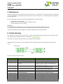
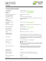
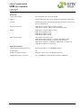
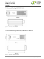
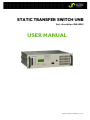
STATIC TRANSFER SWITCH UNB (Incl. description UNB-WEB) USER MANUAL Eltek_UM_UNB_incl-WEB_E_R6.1.docx Static Transfer Switch UNB (incl. UNB-WEB) User Manual Page 2 (36) About this manual IMPORTANT! Read this manual very carefully before installing and commissioning the specified module. This manual is a part of the delivered module. Familiarity with the contents of this manual is required for installing and operating the specified module. The rules for prevention of accidents for the specific country and the general safety rules in accordance with IEC 364 must be observed. The function description in this manual corresponds to the date of publishing. Technical changes and changes in form and content can be made at any time by the manufacturer without notice. There are no obligations to update the manual continually. The module is manufactured in accordance with applicable DIN and VDE standards such as VDE 0106 (part 100) and VDE 0100 (part 410). The CE marking on the module confirms compliance with EU standards 2006-95-EG (low voltage) and 2004-108-EG (electromagnetic compatibility) if the installation and operation instructions are followed. Supplier: FAX Email Internet ELTEK DEUTSCHLAND GmbH BU Industrial Schillerstraße 16 D-32052 Herford + 49 (0) 5221 1708-210 + 49 (0) 5221 1708-222 [email protected] http://www.eltek.com Please note: No part of this document may be reproduced or transmitted in any form or by any means -electronic or mechanical, including photocopying and recording- for whatever reason without the explicit written permission of Eltek Deutschland GmbH. Changes and errors excepted. 2012. ELTEK DEUTSCHLAND GmbH. All rights reserved. ©2012. Eltek Deutschland GmbH. Eltek_UM_UNB_incl-WEB_E_R6.1.docx Static Transfer Switch UNB (incl. UNB-WEB) User Manual Page 3 (36) Revision history Revision: 6.1 Date: 2012-11-06 Revision Description of change Writer Date 01 First edition RTH 2007-04-26 02 Layout change, minor text modifications, UNB30.0 inserted. RTH 2008-01-14 03 Minor text modifications, “Remote switch ON” added. RTH 2008-06-05 04 Minor text modifications at section 2.2 "Operating modes". RTH 2010-05-14 5.0 New revision numbering (X.X) introduced, section “Commissioning” reworked, “Index of figures” included, section “Appendix” including “service menus” included, minor layout changes. RTH 2011-05-30 5.1 Heading line corrected RTH 2012-01-12 6.0 UNB-WEB inserted RTH 2012-02-07 6.1 Photos updated, pinning of connectors X1 & X2 (pin 9) of UNB30.0 & RTH 40.0 corrected, minor text modification 2012-11-06 ©2012. Eltek Deutschland GmbH. Eltek_UM_UNB_incl-WEB_E_R6.1.docx Static Transfer Switch UNB (incl. UNB-WEB) User Manual Page 4 (36) Contents 1A. SAFETY INSTRUCTIONS & NOTES TO ELECTRONIC WASTE DISPOSAL........................................................... 6 2. GENERAL INFORMATION ABOUT THE UNB ............................................................................................................ 7 2.1 Example of use ..................................................................................................................................................... 7 2.2 Operating modes .................................................................................................................................................. 8 2.2.1 "Inverter priority" (factory default setting) ................................................................................................................. 8 2.2.2 "Mains priority" .................................................................................................................................................................. 8 3. TYPE LIST AND MAIN DATA ...................................................................................................................................... 9 3.1 Optional equipment for UNB assembly: ........................................................................................................ 10 3.2 Front View and Operating Elements .............................................................................................................. 10 3.2.1 Front view UNB5.0/12.5kVA ........................................................................................................................................ 10 3.2.2 Front view UNB23.0/30.0/40.0kVA ........................................................................................................................... 11 3.3 Electrical Connectors ........................................................................................................................................ 12 3.3.1 Input terminals ................................................................................................................................................................ 12 3.3.2 Output terminals............................................................................................................................................................. 12 3.3.3 Connectors UNB 5.0 and UNB 12.5kVA ..................................................................................................................... 13 3.3.4 Connectors UNB 23.0kVA ............................................................................................................................................. 14 3.3.5 Connectors UNB 30.0kVA & UNB 40.0kVA ............................................................................................................... 15 3.3.6 Pinning of the CAN bus connectors ............................................................................................................................ 16 3.3.7 Pinning of the front side Ethernet connector (RJ45)............................................................................................... 16 3.4 Cooling/air flow direction ................................................................................................................................. 17 3.5 CAN-Bus communication interface ................................................................................................................ 18 3.6 UNB-WEB with ethernet (net connection) .................................................................................................... 19 4. HANDLING .................................................................................................................................................................. 20 4.1 Storage ................................................................................................................................................................. 20 4.2 Before commissioning ....................................................................................................................................... 20 4.3 Commissioning .................................................................................................................................................... 20 4.4 Operation ............................................................................................................................................................. 21 4.4.1 LED indication .................................................................................................................................................................. 21 4.4.2 Operation keys ................................................................................................................................................................ 21 4.4.3 LCD panel / Indication of measuring values & alarm messages ............................................................................ 22 4.5 Parameter adjustments .................................................................................................................................... 23 4.5.1 Table “Adjustable Parameters” (customer menu) .................................................................................................... 23 4.5.2 Diagram “Customer menu” ............................................................................................................................................ 24 5. MAINTENANCE .......................................................................................................................................................... 26 6. TROUBLE SHOOTING ................................................................................................................................................ 26 7. TECHNICAL SPECIFICATIONS .................................................................................................................................. 27 7.1 Dimensional Drawings UNB5.0/12.5 kVA: ..................................................................................................... 29 7.2 Dimensional Drawings UNB23.0kVA, UNB30.0kVA & 40.0 kVA: ............................................................... 29 7.3 Photo UNB5.0/12.5kVA .................................................................................................................................... 30 7.4 Photo UNB23.0/30.0/40.0kVA ....................................................................................................................... 30 ©2012. Eltek Deutschland GmbH. Eltek_UM_UNB_incl-WEB_E_R6.1.docx Static Transfer Switch UNB (incl. UNB-WEB) User Manual Page 5 (36) 8. APPENDIX (SERVICE MENUS).................................................................................................................................. 31 8.1 Service menu 1 ................................................................................................................................................... 31 8.1.1 Table “Adjustable parameters” (service menu 1) ..................................................................................................... 31 8.1.2 Flow chart “Service menu 1” ......................................................................................................................................... 32 8.1.3 Selection of “Service menu 1” ...................................................................................................................................... 32 8.2 Service menü 2 ................................................................................................................................................... 33 8.2.1 Table “adjustable parameters” (service menu 2) ..................................................................................................... 33 8.2.2 Flow chart „Service menu 2“ ......................................................................................................................................... 34 8.2.3 Selection of “Service menu 2” ...................................................................................................................................... 34 Your notes .................................................................................................................................................................. 35 Index of figures Figure 1) - Single line diagram “Example of use”...................................................................................................... 7 Figure 2) - Front view UNB 5.0/12.5 kVA with Ethernet interface .................................................................... 10 Figure 3) - Front view UNB 23.0/30.0/40.0 kVA with Ethernet interface ........................................................ 11 Figure 4) - Rear view UNB 5.0/12.5 kVA .................................................................................................................. 13 Figure 5) - Connector X1 (HAN-K4/8, socket outlet)............................................................................................ 13 Figure 6) - Rear view UNB 23.0 kVA ......................................................................................................................... 14 Figure 7) - Connectors UNB 23.0 kVA ...................................................................................................................... 14 Figure 8) - Rear view UNB 30.0 & 40.0 kVA ............................................................................................................. 15 Figure 9) - Connectors UNB 30.0 & 40.0 kVA ......................................................................................................... 15 Figure 10a) - CAN bus connector (socket outlet RJ11, 6-pole) .......................................................................... 16 Figure 10b) - Front side Ethernet connector .......................................................................................................... 16 Figure 11) - Cooling/air flow direction ..................................................................................................................... 17 Figure 12) - Sample screenshot “Net Connection” ................................................................................................ 19 Figure 13) - LC Display: Indication of measured values & alarm messages ..................................................... 22 Figure 14) - Diagram “Customer menu”.................................................................................................................... 24 Figure 15) - Diagram “Customer menu”, continuation .......................................................................................... 25 Figure 16) - Display “Alarm messages” .................................................................................................................... 26 Figure 17) - Dimensions UNB5.0/12.5kVA .............................................................................................................. 29 Figure 18) - Dimensions UNB23.0 to 40.0kVA ........................................................................................................ 29 Figure 19) - Photo UNB23.0 to 40.0kVA .................................................................................................................. 30 Figure 20) - Flow chart “Service menu 1” ................................................................................................................ 32 Figure 21) - Flow chart “Service menu 2” ................................................................................................................ 34 ©2012. Eltek Deutschland GmbH. Eltek_UM_UNB_incl-WEB_E_R6.1.docx Static Transfer Switch UNB (incl. UNB-WEB) User Manual Page 6 (36) 1A. Safety instructions & notes to electronic waste disposal Warning! Because several components of operating electrical modules are charged by dangerous voltage, the improper handling of electrical modules may cause accidents involving electrocution, injury, or material damages. • Operation and maintenance of electrical devices must be performed by qualified skilled personnel such as electricians in accordance with EN 50110-1 or IEC 60950. • Install the device only in areas with limited access to unskilled personnel. • Before starting work, the device must be disconnected from mains. Make sure that the device is earthed. • Do not touch connector pins as they can be charged with dangerous voltage up to 30 seconds after disconnection. • Only spare parts approved by the manufacturer must be used. The correct disposal of electronic waste is the responsibility to recycle discarded electronic equipment and is necessary to achieve the chosen level to protect human health and the environment. In the case of waste disposal of your discarded equipment we recommend to contact a professional waste management company. ©2012. Eltek Deutschland GmbH. Eltek_UM_UNB_incl-WEB_E_R6.1.docx Static Transfer Switch UNB (incl. UNB-WEB) User Manual Page 7 (36) 2. General information about the UNB Static transfer switches of the UNB model range are designed for nominal switching capacity of 5.0 kVA up to 40.0 kVA. They are used for nearly interruption free switching (<4 ms) between two AC sources (usually inverter and substitute-mains supply). The static transfer switch synchronises frequency and phasing of mains with the inverters. Basically it is intended for operation in combination with inverters of series UNV and PWS as well but it also works with inverters of series INV. Consequently AC consumers can be driven nearly without interruption if one of the two power sources fails. All operation and indication elements are user-friendly integrated in the front plate of the unit. The UNB is equipped with rear side connectors and is designed to be mounted in a 19’’ compatible mounting kit (see section 3.1). NOTE: UNB modules are available with Ethernet interface on request (see section 3 “Type list” and section 3.6 “UNB-WEB” as well). 2.1 Example of use Inverter system with integrated static transfer switch UNB. Figure 1) - Single line diagram “Example of use” ©2012. Eltek Deutschland GmbH. Eltek_UM_UNB_incl-WEB_E_R6.1.docx Static Transfer Switch UNB (incl. UNB-WEB) User Manual Page 8 (36) 2.2 Operating modes The static transfer switch UNB is designed for the operating modes “inverter priority” and “mains priority” alternatively. Source 1 is defined as priority source, source 2 is defined as substitute source. Source 1 feeds the load as long as source 1 works faultlessly. NOTE: The priority source is programmable using service menu 2 (see section 8 “Appendix”). 2.2.1 "Inverter priority" (factory default setting) The unit's default setting is "Inverter priority". In this case the inverters are source 1 whereas mains is source 2. The UNB switches to source 2 if source 1 fails or is overloaded (i.e. distortions by short circuit behaviour or overload). 2.2.2 "Mains priority" At operating mode “mains priority” AC mains works as source 1 and the inverter(s) as source 2. At this configuration the UNB remains at mains operation whereas the inverter remains synchronized to mains. If mains error occurs, the UNB switches to inverter operation. ©2012. Eltek Deutschland GmbH. Eltek_UM_UNB_incl-WEB_E_R6.1.docx Static Transfer Switch UNB (incl. UNB-WEB) User Manual Page 9 (36) 3. Type list and main data UNB standard UNB-WEB* Battery voltage (VDC) Rated switching capacity (kVA @ 230VAC) Type designation Material code Type designation Material code UNB5.0-24 600-050-411.00 UNB5.0-24-WEB 600-050-411.20 24 5.0 UNB5.0-48 600-050-511.00 UNB5.0-48-WEB 600-050-511.20 48 5.0 UNB5.0-60 600-050-611.00 UNB5.0-60-WEB 600-050-611.20 60 5.0 UNB5.0-110 600-050-711.00 UNB5.0-110-WEB 600-050-711.20 108 5.0 UNB5.0-220 600-050-811.00 UNB5.0-220-WEB 600-050-811.20 216 5.0 UNB12.5-24 600-125-411.00 UNB12.5-24-WEB 600-125-411.20 24 12.5 UNB12.5-48 600-125-511.00 UNB12.5-48-WEB 600-125-511.20 48 12.5 UNB12.5-60 600-125-611.00 UNB12.5-60-WEB 600-125-611.20 60 12.5 UNB12.5-110 600-125-711.00 UNB12.5-110-WEB 600-125-711.20 108 12.5 UNB12.5-220 600-125-811.00 UNB12.5-220-WEB 600-125-811.20 216 12.5 UNB23.0-24 600-230-411.00 UNB23.0-24-WEB 600-230-411.20 24 23.0 UNB23.0-48 600-230-511.00 UNB23.0-48-WEB 600-230-511.20 48 23.0 UNB23.0-60 600-230-611.00 UNB23.0-60-WEB 600-230-611.20 60 23.0 UNB23.0-110 600-230-711.00 UNB23.0-110-WEB 600-230-711.20 108 23.0 UNB23.0-220 600-230-811.00 UNB23.0-220-WEB 600-230-811.20 216 23.0 UNB30.0-24 600-300-411.00 UNB30.0-24-WEB 600-300-411.20 24 30.0 UNB30.0-48 600-300-511.00 UNB30.0-48-WEB 600-300-511.20 48 30.0 UNB30.0-60 600-300-611.00 UNB30.0-60-WEB 600-300-611.20 60 30.0 UNB30.0-110 600-300-711.00 UNB30.0-110-WEB 600-300-711.20 108 30.0 UNB30.0-220 600-300-811.00 UNB30.0-220-WEB 600-300-811.20 216 30.0 UNB40.0-24 600-400-411.00 UNB40.0-24-WEB 600-400-411.20 24 40.0 UNB40.0-48 600-400-511.00 UNB40.0-48-WEB 600-400-511.20 48 40.0 UNB40.0-60 600-400-611.00 UNB40.0-60-WEB 600-400-611.20 60 40.0 UNB40.0-110-WEB 600-400-711.20 108 40.0 216 40.0 UNB40.0-110 600-400-711.00 UNB40.0-220 600-400-811.00 UNB40.0-220-WEB 600-400-811.20 *UNB modules with WEB connectivity (Ethernet interface) are available on request. See section 7) for detailed technical data. ©2012. Eltek Deutschland GmbH. Eltek_UM_UNB_incl-WEB_E_R6.1.docx Static Transfer Switch UNB (incl. UNB-WEB) User Manual Page 10 (36) 3.1 Optional equipment for UNB assembly: Article Article code Suitable for: Mounting set 880-MEC-MKT.01 UNB5.0 & UNB12.5 model range Mounting set 880-MEC-MKT.03 UNB23.0, UNB30.0 & UNB40.0 model range 3.2 Front View and Operating Elements 3.2.1 Front view UNB5.0/12.5kVA Digital display LED indicators Ethernet interface RJ45, 8-pole (Blind plug at UNB standard) Two CAN connectors Operation keys Figure 2) - Front view UNB 5.0/12.5 kVA with Ethernet interface NOTE: The standard UNB is not equipped with an Ethernet interface. Instead of the RJ45 connector is there a blind plug. ©2012. Eltek Deutschland GmbH. Eltek_UM_UNB_incl-WEB_E_R6.1.docx Static Transfer Switch UNB (incl. UNB-WEB) User Manual Page 11 (36) 3.2.2 Front view UNB23.0/30.0/40.0kVA Digital display LED indicators Two CAN connectors Ethernet interface RJ45, 8-pole (Blind plug at UNB standard) Operation keys Figure 3) - Front view UNB 23.0/30.0/40.0 kVA with Ethernet interface NOTE: The standard UNB is not equipped with an Ethernet interface. Instead of the RJ45 connector is there a blind plug. All operating elements and indicators are located at the front of the modules: • • • 4 operation keys: (up), (down), “ESC”, “ENTER”. 7 LED indicators: “STANDBY”, “SOURCE 1”, “SOURCE 2”, “SYNCHR.”, “LOAD ON INVERTER”, “LOAD ON MAINS”, “ALARM”. Digital display For detailed information concerning operating elements, LED indicators, digital display and connectors please see the following chapters. ©2012. Eltek Deutschland GmbH. Eltek_UM_UNB_incl-WEB_E_R6.1.docx Static Transfer Switch UNB (incl. UNB-WEB) User Manual Page 12 (36) 3.3 Electrical Connectors 3.3.1 Input terminals The UNB is equipped with two AC inputs, one for the inverter and the other for the substitute-mains. Both sources must have the same frequency and the same nominal voltage level. Because there are no protection fuses integrated in the unit, both sources must be protected externally. If several inverters are connected in parallel, the parallel connection of the inverter outputs has to be arranged externally. NOTE: If inverters of series PWS are connected in parallel, one symmetry-choke per each individual inverter must be daisy-chained with the L-phase additionally. The AC input connectors are located at the rear side of the unit. Because of the limited load capacity of the connector pins the UNB with an output power of 23.0 kVA is equipped with two connectors, the 30.0 & 40.0 kVA unit with three connectors with several contact pins connected in parallel accordingly. In that case the related contact pins require an identical cable diameter and length. This applies also to the AC output connection terminal which is described in the following. Additional the UNB is equipped with a DC input for the connection to the battery of the system. The internal electronic circuit of the UNB is supplied by mains and additionally by the battery (redundancy). The voltage level of the battery is monitored by the UNB; the result is used for switching off the inverters in case of over/under voltage. The UNB measures and monitors the voltage level of both input sources (real effective values) and additional the frequencies. The thresholds of those measuring values are programmable (factory setting, only practicable by skilled service personnel). 3.3.2 Output terminals The unit is equipped with a plug-in AC output connection terminal. In case of short circuit, the short circuit power is transferred to the UNB input, which causes the fuse of source 1 or 2 to be blown. The UNB should be overloaded only for short-time (see technical data). In particular this is to be observed for the correct dimensioning of the prefuse. The pre-fuse must be dimensioned according to the nominal switching capacity of the UNB. If the pre-fuse is oversized, the resultant delayed fuse tripping may destroy the internal thyristors of the UNB. Operation of UNB in combination with inverters of series UNV: The UNB measures and monitors the current of the consumer load. In order to avoid a permanent overload of the inverters the UNB verifies the availability of the connected inverters and recalculates the allowed total current of the consumer load. If one of the inverters in parallel operation fails, the overload threshold value is automatically reduced accordingly. ©2012. Eltek Deutschland GmbH. Eltek_UM_UNB_incl-WEB_E_R6.1.docx Static Transfer Switch UNB (incl. UNB-WEB) User Manual Page 13 (36) 3.3.3 Connectors UNB 5.0 and UNB 12.5kVA 1 3 X1 2 4 Figure 4) - Rear view UNB 5.0/12.5 kVA 9 5 10 6 11 7 12 8 Figure 5) - Connector X1 (HAN-K4/8, socket outlet) Pins (X1) 1 2 3 4 5 6 7 8 9 10 11 12 Function Source 1 (inverter)/Phase L1 Source 2 (substitute mains)/Phase L1 Source 1 & 2/ neutral UNB Output/Phase L1 DC-supply / L+ (24/48/108/216 VDC) DC-supply / L- (24/48/108/216 VDC) Synchronization / SYNC-SIG Synchronization / SYNC-STAT Remote switch ON (+24 V) Indication relay general fault / NO Indication relay general fault / COM* Synchronization / SYNC-GND *Function logic: OK = COM and NO closed (Is equal to the programming “not inverted”) NOTE: If the UNB works in combination with a single inverter or inverters in parallel operation it is necessary to connect through the synchronization bus (contacts SYNC-GND→ SYNC-GND, SYNC-SIG→ SYNC-SIG and SYNC-STAT→ SYNC-STAT) between the inverter(s) and the UNB. ©2012. Eltek Deutschland GmbH. Eltek_UM_UNB_incl-WEB_E_R6.1.docx Static Transfer Switch UNB (incl. UNB-WEB) User Manual Page 14 (36) 3.3.4 Connectors UNB 23.0kVA 1 1 3 3 2 2 4 Figure 6) - Rear view UNB 23.0 kVA 4 9 5 9 5 10 6 10 6 11 7 11 7 12 8 12 8 Connector X1 Connector X2 Figure 7) - Connectors UNB 23.0 kVA Pins (X1) 1 2 3 4 5 6 7 8 9 10 11 12 Function Source 1 (inverter)/Phase L1 Source 2 (substitute mains)/Phase L1 Source 1 & 2/ neutral UNB Output/Phase L1 DC-supply / L+ (24/48/108/216 VDC) DC-supply / L- (24/48/108/216 VDC) Synchronization / SYNC-SIG Synchronization / SYNC-STAT Indication relay general fault / NC Indication relay general fault / NO Indication relay general fault / COM* Synchronization / SYNC-GND Pins (X2) 1 2 3 4 5 6 7 8 9 10 11 12 Function Source 1 (inverter)/Phase L1 Source 2 (substitute mains)/Phase L1 No connection UNB Output/Phase L1 n/c n/c n/c n/c Remote switch ON (+24 V) n/c n/c n/c *Function logic: fault = COM and NC closed OK = COM and NO closed (Is equal to the programming “not inverted”) NOTE: If the UNB works in combination with a single inverter or inverters in parallel operation it is necessary to connect through the synchronization bus (contacts SYNC-GND→ SYNC-GND, SYNC-SIG→ SYNC-SIG and SYNC-STAT→ SYNC-STAT) between the inverter(s) and the UNB. ©2012. Eltek Deutschland GmbH. Eltek_UM_UNB_incl-WEB_E_R6.1.docx Static Transfer Switch UNB (incl. UNB-WEB) User Manual Page 15 (36) 3.3.5 Connectors UNB 30.0kVA & UNB 40.0kVA 1 1 3 1 3 3 2 2 4 2 4 4 Figure 8) - Rear view UNB 30.0 & 40.0 kVA 9 5 9 5 9 5 10 6 10 6 10 6 11 7 11 7 11 7 12 8 12 8 12 8 Connector X1 Connector X2 Connector X3 Figure 9) - Connectors UNB 30.0 & 40.0 kVA Pins (X1) 1 2 3 4 5 6 7 8 9 10 11 12 Function Source 1 (inverter) / Phase L1 Source 1 (inverter) / Phase L1 Source 1 (inverter) / Phase L1 n/c n/c Synchronization / SYNC-GND Synchronization / SYNC-SIG Synchronization / SYNC-STAT n/c n/c n/c n/c Pins (X2) 1 2 3 4 5 6 7 8 9 10 11 12 Function Source 2 (substitute mains) / Phase L1 Source 2 (substitute mains) / Phase L1 Source 2 (substitute mains) / Phase L1 Source 1 & 2 / neutral DC-supply / L+ DC-supply / Ln/c n/c Remote switch ON (+24 V) Indication relay general fault / COM* Indication relay general fault / NO Indication relay general fault / NC *Function logic: fault = COM and NC closed OK = COM and NO closed (Is equal to the programming “not inverted”) NOTE: If the UNB works in combination with a single inverter or inverters in parallel operation, it is necessary to connect through the synchronization bus (contacts SYNC-GND→ SYNC-GND, SYNC-SIG→ SYNC-SIG and SYNCSTAT→ SYNC-STAT) between the inverter(s) and the UNB. Pins (X3) 1 2 3 4 5 6 7 8 9 10 11 12 Function UNB Output/Phase L1 UNB Output/Phase L1 UNB Output/Phase L1 n/c n/c n/c n/c n/c n/c n/c n/c n/c ©2012. Eltek Deutschland GmbH. Eltek_UM_UNB_incl-WEB_E_R6.1.docx Static Transfer Switch UNB (incl. UNB-WEB) User Manual Page 16 (36) 3.3.6 Pinning of the CAN bus connectors The UNB is equipped with two CAN connectors (CAN1 and CAN2) at the front of the unit. Figure 10a) - CAN bus connector (socket outlet RJ11, 6-pole) Connection table: Pin Signals CAN1 Signals CAN2 Designation 1 2 CAN_V+ DC-Supply +8 to 15 V CAN_V+ DC-Supply +8 to 15 V 3 CAN_H Signal (high) 4 CAN_L Signal (low) 5 CAN_V- DC-Supply Ground 6 CAN_V- DC-Supply Ground 3.3.7 Pinning of the front side Ethernet connector (RJ45) Pin Name Designation 1 TX+ Tranceive Data + 2 TX- Tranceive Data - 3 RX+ Receive Data + 4 n/c Not used 5 n/c Not used 6 RX- Receive Data - 7 n/c Not used 8 n/c Not used Figure 10b) - Front side Ethernet connector (socket outlet RJ45, 8-pole) ©2012. Eltek Deutschland GmbH. Eltek_UM_UNB_incl-WEB_E_R6.1.docx Static Transfer Switch UNB (incl. UNB-WEB) User Manual Page 17 (36) 3.4 Cooling/air flow direction The unit is cooled by internal fan. The airflow is from the front to rear side. The fan is monitored and speed controlled dependent on module temperature. To provide sufficient air flow, a minimum space (see item “A” in figure 11) of 50 mm is required between the unit and the rear cabinet wall as well as an unobstructed supply of air to the front of the module. Figure 11) - Cooling/air flow direction ©2012. Eltek Deutschland GmbH. Eltek_UM_UNB_incl-WEB_E_R6.1.docx Static Transfer Switch UNB (incl. UNB-WEB) User Manual Page 18 (36) 3.5 CAN-Bus communication interface The UNB is equipped with serial data interface according to CAN (= Controller Area Network)-specification. Two CAN-Bus connectors are integrated in the front plate of the unit. The UNB communicates via CAN-Bus with the connected inverters and a possibly implemented supervision monitoring device of the UPC model range or MU1000C). Following information is available via CAN-Bus: • • • • • • • • Status information of the UNB Availability of the connected inverters Availability of the substitute mains Output current of the UNB Device temperature Battery-voltage at the UNB Frequency of source 1 and source 2 Input- and output values of the connected inverters as follows: o Input current o Input voltage o Output current o Output voltage o Output frequency o Device status (okay/not okay) (The values are measured at regular intervals via CAN-Bus and can be selected at the display using the operation keys). If the signal to one of the connected inverters is interrupted, the failure message “CAN failure” is indicated and the number of the particular inverter is shown. The numbering of the inverters automatically follows the CAN addresses in ascending order which have been adjusted at the inverters. The output voltage of the connected inverters is controlled by the UNB via CAN-Bus according to the adjusted value “mains voltage” in the service menu 1 (factory setting, only practicable by skilled service personnel). If the CAN-Bus connection is inactive for more than five seconds, the inverters switch automatically back to the internally stored default values. The inverters are switched off by the UNB if Vbatt> Vmax (default value= 2.5V x number of cells) or Vbatt< Vmin (default value= 1.7V x number of cells) is detected by the UNB. NOTE: The internally stored value (output voltage of the inverter Vo) must be the same for all of the inverters which are connected in parallel and the same value must be adjusted at the UNB. Detailed information regarding the adjustment of “Vo” can be found in the user manuals of the particular inverters. The CAN bus is not relevant for the synchronization of the inverters. For safety reasons, the synchronization takes place via the hard-wired synchronization bus between inverters and UNB (please see section 3.3.3 “connectors” et seq.). ©2012. Eltek Deutschland GmbH. Eltek_UM_UNB_incl-WEB_E_R6.1.docx Static Transfer Switch UNB (incl. UNB-WEB) User Manual Page 19 (36) 3.6 UNB-WEB with ethernet (net connection) The UNB is available on request with front side Ethernet interface (10/100 MB) for remote control via HTTP (WEB server), SNMP, SMTP und SNTP. The UNB can be directly configured via PC. Furthermore, extensive remote control can be realized. Figure 12) - Sample screenshot “Net Connection” NOTE: A specific manual “Net Connection” is separately available. ©2012. Eltek Deutschland GmbH. Eltek_UM_UNB_incl-WEB_E_R6.1.docx Static Transfer Switch UNB (incl. UNB-WEB) User Manual Page 20 (36) 4. Handling 4.1 Storage The UNB must be stored in a dry, dust free environment with a storage temperature according to specified data (see section 7). 4.2 Before commissioning 1. 2. Battery system: The static transfer switch UNB is delivered with factory-configured defaults according to lead acid batteries with cell numbers according to nominal DC input voltage (see the table below) of the device. If other battery systems with different cell numbers should be used, the UNB must be reconfigured before. Device name Nominal DC input voltage UNB is factory-configured for: UNBxxx-24 24 V Lead acid battery, 12 cells UNBxxx-48 48 V Lead acid battery, 24 cells UNBxxx-60 60 V Lead acid battery, 30 cells UNBxxx-110 108 V Lead acid battery, 54 cells UNBxxx-220 216 V Lead acid battery, 108 cells Number of used inverters and output power per one inverter must be configured in any case. The adjustment of the number of inverters has to be done in the Customer menu (see section 4.5.1). If inverters of the PWS family should be used, the number of inverters must be set to “0”. The nominal output power of one inverter has to be configured in Service menu 1 (see section 8.1). The factory preset defaults and threshold values and their adjustment ranges/steps as well are listed in the Service Menus (please see section 8 „Appendix“). If necessary, reconfiguration of the UNB can be carried out using the adjustment keys. Operation using adjustment keys and menu navigation as well is described in the following sections. Adjustments at the UNB can be carried out if either the related DC voltage is connected to the DC input or AC voltage is connected to the AC input of the UNB. 4.3 Commissioning NOTE: Before commissioning make sure that the AC voltage and frequency as well of substitute mains and DC input voltage (battery) as well corresponds to the specification as specified on the type plate. Make sure that the UNB is correctly configured according to the used battery system (see section 4.2 above “Before commissioning”). A mounting-kit according to section 3.1 “Optional equipment…” is necessary to mount the UNB into a 19’’ compatible cabinet. After unpacking the unit put it upon the rails and slide in the unit carefully over the rails until the module connector gets in touch with the backplane connector. Increase the pressure until the unit fits in completely. Please avoid too much pressure. If the unit does not fit in please start again with the complete slide-in process. Mount the unit with 4 screws (M4x12). CAUTION: The unit is delivered without internal fuses. Therefore the unit must be fused externally at the input source “mains” to protect the internal thyristors against damages in case of short circuit. The pre-fuse must be dimensioned according to the nominal switching capacity of the UNB. In case of inverters in parallel operation, the output of each inverter must be fused. Connect the unit to the system according to section 3.3 “Electrical connectors”. ©2012. Eltek Deutschland GmbH. Eltek_UM_UNB_incl-WEB_E_R6.1.docx Static Transfer Switch UNB (incl. UNB-WEB) User Manual Page 21 (36) 4.4 Operation The operation and adjustment respectively of the unit takes place with keys located at the front side of the unit. All main functional parameters and measuring values are displayed on the front side LCD panel (text indicator) as well as by LED indications. They are described in the following. 4.4.1 LED indication LED Indication Colour Operation mode STANDBY green SOURCE 1 green SOURCE 2 green SYNCHR. green Inverters are synchronised with mains by UNB LOAD ON INVERTER green Load fed by inverter LOAD ON MAINS green Load fed by mains ALARM red The UNB is switched on and operational Voltage and frequency of source 1 (priority source) are within allowable range Voltage and frequency of source 2 (substitute source) are within allowable range General Alarm (the assignment of the individual alarm messages is programmable) 4.4.2 Operation keys The adjustment takes place with four front keys as described in the following: Front keys Indication Function during menu item selection: change to previous item (parameter) during adjustment mode: increase value Up during menu item selection: change to next item (parameter) during adjustment mode: decrease value Escape leave the menu without changing Enter call menu leave menu with changing save parameter Down ©2012. Eltek Deutschland GmbH. Eltek_UM_UNB_incl-WEB_E_R6.1.docx Static Transfer Switch UNB (incl. UNB-WEB) User Manual Page 22 (36) 4.4.3 LCD panel / Indication of measuring values & alarm messages At initial state the display shows the measuring values of the input sources (AC output voltage of inverter, mains voltage, output current, date and time, additional frequencies of inverter and mains and battery voltage as well as the total DC-current). Figure 13) - LC Display: Indication of measured values & alarm messages Display [1] shows the initial state (basic display). The plain text of the basic display becomes visible after successful start-up procedure. According to the diagram above (see figure 13) you can select the displays [1], [2] and [3] by pushing the keys or : • • • If no inverter is registered, display [3] is not available. If exactly one inverter is registered, display [3] is visible without inverter number. If more than one inverter is registered, it is possible to call the parameters (input current, output current and status) of all connected inverters in succession by pressing “ENTER”. The inverter number is shown in the first line of the display. The display automatically reverts to display [1] if no key is pressed for a period of more than 30 seconds. Display [4] “Alarm messages” indicates the current alarm status. It can be selected from display [1] or [2] by pressing “ESC”. By pressing the keys or you are able to leaf through the list of alarm messages if more than three entries are present there. The display “Alarm messages” can be quit by pressing “ESC” again. Basically (factory setting) all individual failures according to “list of the selectable individual collective failures“ (please see section 4.5.1) are enabled and therefore they are visible on the display in case of failure. The alarm messages which shall not be visible on the display in case of failure have to be disabled in the customer menu (please see the diagram “Customer menu”). ©2012. Eltek Deutschland GmbH. Eltek_UM_UNB_incl-WEB_E_R6.1.docx Static Transfer Switch UNB (incl. UNB-WEB) User Manual Page 23 (36) 4.5 Parameter adjustments The static switch UNB is delivered with factory-configured defaults according to lead acid batteries with cell numbers according to nominal DC input voltage of the device (see section 4.2 “Before commissioning”). If other battery systems with different cell numbers should be used, the UNB must be reconfigured before. In this case reconfiguration takes place using service menu 1 and 2 (see section 8 „Appendix“). ATTENTION! Configuration should be carried out only by qualified and skilled service personnel. In the following sections the adjustable parameters in the customer menu (accessible to each customer) are described. Those are general adjustments such as number of used inverters, indicated display language, time delay values, content of collective failure signal etc. 4.5.1 Table “Adjustable Parameters” (customer menu) In the customer menu the parameters can be adjusted according to the table as follows: Menu item Functions Range INV-count Time/Date 0- 15 Delay LED CF Delay Relay CF LCD-contrast LCD backlight Key in the number of the connected inverters* Adjustment of the real time clock Selection (switching active/inactive) of individual failures for the collective failure signalisation= General Alarm (LED and Relay) LED time delay of the collective failure signal Time delay of the collective failure relay Contrast adjustment of the display Background illumination Language Selection of the language Softw. version? Shows the current firmware version Configuration CF Default value (factory setting) 0 All individual failures** 1- 60 sec 1- 60 sec 0- 255 On / off English, German, Polish, Swedish, Italian Read only All enabled 30 30 220 On English * If the UNB works together with inverters of type PWS, the INV-count must be set to “0” because the PWS is not equipped with CAN interface. Otherwise, the failure message “Inverter fail.” would be generated. **List of the selectable individual collective failures (CF): Alarm message Source 1 fail. Source 2 fail. Synchr. Error Inverter fail. UNB overtemp. UNB overload INV overload DC voltage low DC voltage high Ubatt< warning Ubatt> warning Meaning Voltage or frequency of source 1 not OK Voltage or frequency of source 2 not OK Mains and INV voltage are not synchronous Inverter error UNB over temperature UNB output current too high The output current exceeds the inverter power Battery voltage low Battery voltage high Battery voltage < warning level Battery voltage > warning level ©2012. Eltek Deutschland GmbH. Eltek_UM_UNB_incl-WEB_E_R6.1.docx Static Transfer Switch UNB (incl. UNB-WEB) User Manual Page 24 (36) 4.5.2 Diagram “Customer menu” The customer menu can be entered from the basic display by pressing ENTER for around three seconds and then press ENTER again. A list of all selectable individual collective failures (CF) is shown on the previous page. Figure 14) - Diagram “Customer menu” ©2012. Eltek Deutschland GmbH. Eltek_UM_UNB_incl-WEB_E_R6.1.docx Static Transfer Switch UNB (incl. UNB-WEB) User Manual Page 25 (36) Figure 15) - Diagram “Customer menu”, continuation The final display provides information about the currently used firmware version. ©2012. Eltek Deutschland GmbH. Eltek_UM_UNB_incl-WEB_E_R6.1.docx Static Transfer Switch UNB (incl. UNB-WEB) User Manual Page 26 (36) 5. Maintenance In general, the device is maintenance-free. Exclusively the fan is a component consisting of moving parts. Although it may be expected that the operating life of the fan is more than five years it is recommended to exchange the fan every five years. By way of precaution a yearly inspection with following checks is recommended: • • • Mechanical/visual inspection Removal of dust and dirt, especially on radiator surfaces Check for internal dust or humidity Attention! Dust combined with moisture or water may influence or destroy the internal electronic circuits. Dust inside the unit can be blown out with dry compressed air. Avoid using too high air pressure. The interval between the checks depends on ambient conditions of the installed module. 6. Trouble shooting If a failure occurs in the system, the LED “Alarm” is illuminated according to the adjustments in the customer menu, item “Configuration of Collective Failures” (see diagram “customer menu”). The failures are shown in clear text modus in the display “Alarm messages”. The display “Alarm messages” can be entered from the basic display by pressing ESC (please also see section 4.4.3). Basic display Figure 16) - Display “Alarm messages” Alarm messages Source 1 fail. Source 2 fail. Synchr. Error Possible reason Mains voltage or frequency not ok Inverter voltage or frequency not ok Inverter voltage is not synchronous to mains Inverter fail. Inverter failure UNB overtemp UNB over temperature UNB overload INV overload UNB output current to high Actual output current exceeds the combined INV power Battery voltage low Battery voltage high Battery voltage < warning level Battery voltage > warning level DC-voltage low DC-voltage high Ubatt< warning Ubatt> warning ©2012. Eltek Deutschland GmbH. Corrective action Check mains voltage/inverter output voltage Check inverter output voltage/mains voltage No mains voltage available or frequency of mains voltage is not stable (out of frequency tolerance range) CAN communication with one or more Inverters failed. Inverter failure detected via CAN Check the air flow Check admissible ambient temperature Reduce load current Reduce load current or increase INV power by additional inverter Check DC voltage system Check DC voltage system Check DC voltage system Check DC voltage system Eltek_UM_UNB_incl-WEB_E_R6.1.docx Static Transfer Switch UNB (incl. UNB-WEB) User Manual Page 27 (36) 7. Technical Specifications Type designation Please see section 3 “Type List/Main Data” Material code Please see section 3 “Type List/Main Data” AC input: Nominal input voltage source 1 + 2 220/230/240 VAC, adjustable Input voltage tolerance ±20 % Input frequency range 48 to 52Hz/58 to 62 Hz, adjustable Synchronization range ±2 Hz (in combination with inverters of series PWS the range must be adjusted to ±0.5 Hz). ≥ 99 % Efficiency DC Voltage input: Nominal battery voltage Please see section 3 “Type List/Main Data” AC Output: Nominal output voltage 220/230/240 VAC, adjustable, switch over threshold ±5 to ±20 %, adjustable Nominal output power Please see section 3 “Type List/Main Data” Overload capability 1000 % for 10 ms Output frequency acc. to the input frequency Switch transfer time ≤3 ms Fusing External with rated current, character gL Standard Features: Monitoring functions voltage/frequency of sources 1 and 2; synchronization mains/ inverter; over temperature; CAN communication lost; battery voltage LED indications Operation (green), source 1 OK (green), source 2 OK (green), load on mains (green), load on inverter (green), synchronization (green), collective alarm (red) Alphanumeric display LCD (4 x 16 characters), background lighted Control keys , , ESC, ENTER Fault signalization Text message on LCD; in addition 1 programmable isolated collective failure (alarm) relay, max. contact load: <0.25 ADC @ Vmax < 150 VDC; <0.5 ADC @ Vmax <100 VDC Communication interface CAN-Bus for communication with inverters of type UNV and INV UNB with Ethernet interface (available by request): One RJ45 for remote control via HTTP (Web server), SNMP, SMTP and SNTP. Remote switch ON available Environmental: Ambient temperature operation: -20 °C to +55 °C; storage: -40 °C to + 85 °C Climatic conditions acc. to IEC 721-3-3 class 3K3/3Z1/3B1/3C2/3S2/3M2 Dust <1 mg/m³ Max. installation altitude 1500 m Audible noise ≤45 dBA at 1 m distance ©2012. Eltek Deutschland GmbH. Eltek_UM_UNB_incl-WEB_E_R6.1.docx Static Transfer Switch UNB (incl. UNB-WEB) User Manual Page 28 (36) Mechanical: Type of construction 19’’- compatible rack acc. to DIN 41494 Cooling forced cooling with internal fan (temperature regulated; monitored) Surfaces powder coating RAL 7035 (front panel only), black print; constructive parts: anodized metal Dimensions (W/H/D) UNB 5kVA + 12.5kVA: 483/133/360 mm (3HU) UNB 23kVA + 30kVA + 40kVA: 483/177/460 mm (4HU) Weight UNB 5kVA + 12.5kVA: approx. 12.6 kg UNB 23kVA: approx. 13.2 kg UNB 30kVA: approx. 15.8 kg UNB 40kVA: approx. 16.9 kg Electrical connectors Front side: 2 x CAN-Bus (RJ11); UNB with Ethernet interface: 1 x socket outlet RJ45, 8-pole Rear side: AC inputs/output, DC input and signalization; UNB 5kVA + 12.5kVA: 1 x HAN-K4/8; UNB 23kVA: 2 x HAN-K4/8; UNB 30kVA + 40kVA: 3 x HAN-K4/8 Applicable standards: Type of enclosure/protection class IP20 (front panel) /1 acc. to EN 60950 (electr.) CE conformity yes Compliance to EMC standards EN55011/55022 class “B”; EN61000-4 part 2-5) Compliance to safety standards acc. to EN60950-1; VDO0100 T410; VDO0110; EN60146 ©2012. Eltek Deutschland GmbH. Eltek_UM_UNB_incl-WEB_E_R6.1.docx Static Transfer Switch UNB (incl. UNB-WEB) User Manual Page 29 (36) 7.1 Dimensional Drawings UNB5.0/12.5 kVA: Figure 17) - Dimensions UNB5.0/12.5kVA 7.2 Dimensional Drawings UNB23.0kVA, UNB30.0kVA & 40.0 kVA: Figure 18) - Dimensions UNB23.0 to 40.0kVA ©2012. Eltek Deutschland GmbH. Eltek_UM_UNB_incl-WEB_E_R6.1.docx Static Transfer Switch UNB (incl. UNB-WEB) User Manual Page 30 (36) 7.3 Photo UNB5.0/12.5kVA See first cover page please. 7.4 Photo UNB23.0/30.0/40.0kVA Figure 19) - Photo UNB23.0 to 40.0kVA ©2012. Eltek Deutschland GmbH. Eltek_UM_UNB_incl-WEB_E_R6.1.docx Static Transfer Switch UNB (incl. UNB-WEB) User Manual Page 31 (36) 8. Appendix (service menus) 8.1 Service menu 1 8.1.1 Table “Adjustable parameters” (service menu 1) Menu item Function Adjustable range Adjustment steps Default values INV-nom. power. Key in the nominal output power per inverter 1.0 to 5.0 kVA 0.1 kVA 2.5 kVA Mains voltage Key in the mains voltage value 200 to 250 V AC 1.0 V 230 V Set the mains frequency 50 or 60 Hz Key in the tolerance range for synchronisation ±0.1 Hz to ±2.0 Hz 0.1 Hz UNB current Key in the nominal UNB current 1- 250 A 1.0 A Batt. cellcount1) Key in the number of battery cells 12 to 200 1 Voltage/cell2) Key in the voltage per cell CAN-Status M/S2) Key in the CAN-Status “Master” or “Slave” 1.2 V (NiCd), 2.0 V (Pb) 0= Master, 1 to 31= Slave configur. rel.2 Without function function relay 2 Delay relay 2 Mains frequency Frequency range 50 Hz ±0.5 Hz Dependent on the type Dependent on the type, see table below 2.0 V 1 0 --- --- --- Without function --- --- --- Without function --- --- --- Reset the UNB to default valDefault-values? ues?3) 1) Cell count of the battery (Pb). 2) This menu item is inoperable 3) With the exception of calibrated values. yes/no no Factory-configured number of battery cells at the UNB: Device name Nominal DC input voltage UNB is factory-configured for UNBxxx-24 24 V Lead acid battery, 12 cells UNBxxx-48 48 V Lead acid battery, 24 cells UNBxxx-60 60 V Lead acid battery, 30 cells UNBxxx-110 108 V Lead acid battery, 54 cells UNBxxx-220 216 V Lead acid battery, 108 cells ©2012. Eltek Deutschland GmbH. Eltek_UM_UNB_incl-WEB_E_R6.1.docx Static Transfer Switch UNB (incl. UNB-WEB) User Manual Page 32 (36) 8.1.2 Flow chart “Service menu 1” NOTE: “Service Menu 1” is code protected1. Keep pressing the down button until the display shows the required service code1. xxx1 Figure 20) - Flow chart “Service menu 1” 8.1.3 Selection of “Service menu 1” To attain Service Menu 1 please follow the steps according to the flow chart (see figure 20): 1. 2. 3. 4. 5. 6. Based on the basic display [1] press and hold ENTER (for approx. three seconds) until the display shows “cust. menu” [2]. Press the down button and keep pressing until you get “servicecode: xxx1” [3]. Tip ENTER. You are then in service menu 1 [4]. Pressing the buttons or you are able to leaf through the menu. The arrow () shows the menu item which is selectable by pressing ENTER. The flow chart (see figure 13) shows the selected menu item “INV-nom. power” [5]. Change the values pressing or . Tip ENTER to save the new values; if you tip ESC, the new values are not saved. Tip ESC to return to the basic display. For details concerning the adjustable parameters please see the table above “Adjustable Parameters (Service menu 1)”. 1 Please ask your system supplier if the code is required. ©2012. Eltek Deutschland GmbH. Eltek_UM_UNB_incl-WEB_E_R6.1.docx Static Transfer Switch UNB (incl. UNB-WEB) User Manual Page 33 (36) 8.2 Service menü 2 8.2.1 Table “adjustable parameters” (service menu 2) Menu item Function Adjustable range Operation mode Key in the priority source “Inverter-“ or “mains priority” Source 1> Source 1< Time delay S1 Source 2> Source 2< Time delay S2 Uimax Uimin 11) Uimin 21) Ubatt> Upper tolerance range of source 1 voltage Lower tolerance range of source 1 voltage Key in the time delay of source 1 Upper tolerance range of source 2 voltage Lower tolerance range of source 2 voltage Key in the time delay of source 2 Key in the over voltage switch-off value Key in the under voltage switch-off value Key in the under voltage switch-on again value Key in the over voltage warning value Key in the under voltage warning Ubatt< value Load on Key in: Switch load stationary on mains? mains2) *Number of cells is set at service menu 1. +5 to +20 % -5 to -20 % 0.5 to 4.0 ms +5 to +20% -5 to -20% 0.5 to 4.0 ms 2.00 to 3.00 V/cell 0.70 to 2.50 V/cell 0.60 to 2.50 V/cell 2.20 to 2.50 V/cell 1.70 to 2.10 V/cell Yes/no Adjustment steps Default values Inverter priority 1% 1% 0.5 ms 1% 1% 0.5 ms 0.01 V 0.01 V 0.01 V 0.01 V 0.01 V +15% -15% 2.0 ms +20% -20% 4.0 ms 2.50 V/cell* 1.70 V/cell* 1.90 V/cell* 2.35 V/cell* 1.90 V/cell* no Please note: Uimin 1 < Uimin 2 (hysteresis)! 1) Only suitable for service. Not stored in EEPROM! 2) ©2012. Eltek Deutschland GmbH. Eltek_UM_UNB_incl-WEB_E_R6.1.docx Static Transfer Switch UNB (incl. UNB-WEB) User Manual Page 34 (36) 8.2.2 Flow chart „Service menu 2“ NOTE: “Service Menu 2” is code protected1. Keep pressing the down button until the display shows the required service code1. xxx1 Figure 21) - Flow chart “Service menu 2” 8.2.3 Selection of “Service menu 2” To attain Service Menu 2 please follow the steps according to the flow chart (see figure 21): 1. 2. 3. 4. 5. 6. Based on the basic display [1] press and hold ENTER (for approx. three seconds) until the display shows “cust. menu” [2]. Press the down button and keep pressing until you get “servicecode: xxx1” [3]. Tip ENTER. You are then in service menu 2 [4]. Pressing the buttons or you are able to leaf through the menu. The arrow () shows the menu item which is selectable by pressing ENTER. The flow chart (see figure 14) shows the selected menu item “operating mode” [5]. Change the values pressing or . Tip ENTER to save the new values; if you tip ESC, the new values are not saved. Tip ESC to return to the basic display. For details concerning adjustable parameters see the table above “Adjustable Parameters (Service menu 2)”. 1 Ask your system supplier if the code is required. ©2012. Eltek Deutschland GmbH. Eltek_UM_UNB_incl-WEB_E_R6.1.docx Static Transfer Switch UNB (incl. UNB-WEB) User Manual Page 35 (36) Your notes ©2012. Eltek Deutschland GmbH. Eltek_UM_UNB_incl-WEB_E_R6.1.docx Supplier: FAX Email Internet ELTEK DEUTSCHLAND GmbH BU Industrial Schillerstraße 16 D-32052 Herford + 49 (0) 5221 1708-210 + 49 (0) 5221 1708-222 [email protected] http://www.eltek.com 2012. ELTEK DEUTSCHLAND GmbH. All rights reserved.