1
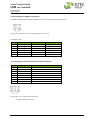
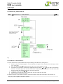
Static Transfer Switch UNB (incl. UNB-WEB) User Manual Page 23 (36) 4.5 Parameter adjustments The static switch UNB is delivered with factory-configured defaults according to lead acid batteries with cell numbers according to nominal DC input voltage of the device (see section 4.2 “Before commissioning”). If other battery systems with different cell numbers should be used, the UNB must be reconfigured before. In this case reconfiguration takes place using service menu 1 and 2 (see section 8 „Appendix“). ATTENTION! Configuration should be carried out only by qualified and skilled service personnel. In the following sections the adjustable parameters in the customer menu (accessible to each customer) are described. Those are general adjustments such as number of used inverters, indicated display language, time delay values, content of collective failure signal etc. 4.5.1 Table “Adjustable Parameters” (customer menu) In the customer menu the parameters can be adjusted according to the table as follows: Menu item Functions Range INV-count Time/Date 0- 15 Delay LED CF Delay Relay CF LCD-contrast LCD backlight Key in the number of the connected inverters* Adjustment of the real time clock Selection (switching active/inactive) of individual failures for the collective failure signalisation= General Alarm (LED and Relay) LED time delay of the collective failure signal Time delay of the collective failure relay Contrast adjustment of the display Background illumination Language Selection of the language Softw. version? Shows the current firmware version Configuration CF Default value (factory setting) 0 All individual failures** 1- 60 sec 1- 60 sec 0- 255 On / off English, German, Polish, Swedish, Italian Read only All enabled 30 30 220 On English * If the UNB works together with inverters of type PWS, the INV-count must be set to “0” because the PWS is not equipped with CAN interface. Otherwise, the failure message “Inverter fail.” would be generated. **List of the selectable individual collective failures (CF): Alarm message Source 1 fail. Source 2 fail. Synchr. Error Inverter fail. UNB overtemp. UNB overload INV overload DC voltage low DC voltage high Ubatt< warning Ubatt> warning Meaning Voltage or frequency of source 1 not OK Voltage or frequency of source 2 not OK Mains and INV voltage are not synchronous Inverter error UNB over temperature UNB output current too high The output current exceeds the inverter power Battery voltage low Battery voltage high Battery voltage < warning level Battery voltage > warning level ©2012. Eltek Deutschland GmbH. Eltek_UM_UNB_incl-WEB_E_R6.1.docx