1
Static Transfer Switch
UNB (incl. UNB-WEB)
User Manual
Page 15 (36)
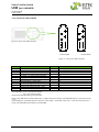
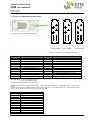
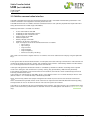
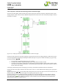
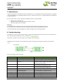
3.3.5 Connectors UNB 30.0kVA & UNB 40.0kVA
1
1
3
1
3
3
2
2
4
2
4
4
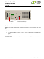
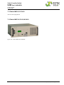
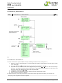
Figure 8) - Rear view UNB 30.0 & 40.0 kVA
9
5
9
5
9
5
10
6
10
6
10
6
11
7
11
7
11
7
12
8
12
8
12
8
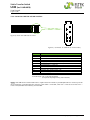
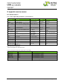
Connector X1
Connector X2
Connector X3
Figure 9) - Connectors UNB 30.0 & 40.0 kVA
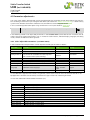
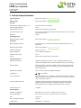
Pins (X1)
1
2
3
4
5
6
7
8
9
10
11
12
Function
Source 1 (inverter) / Phase L1
Source 1 (inverter) / Phase L1
Source 1 (inverter) / Phase L1
n/c
n/c
Synchronization / SYNC-GND
Synchronization / SYNC-SIG
Synchronization / SYNC-STAT
n/c
n/c
n/c
n/c
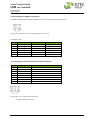
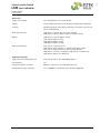
Pins (X2)
1
2
3
4
5
6
7
8
9
10
11
12
Function
Source 2 (substitute mains) / Phase L1
Source 2 (substitute mains) / Phase L1
Source 2 (substitute mains) / Phase L1
Source 1 & 2 / neutral
DC-supply / L+
DC-supply / Ln/c
n/c
Remote switch ON (+24 V)
Indication relay general fault / COM*
Indication relay general fault / NO
Indication relay general fault / NC
*Function logic: fault = COM and NC closed
OK = COM and NO closed
(Is equal to the programming “not inverted”)
NOTE: If the UNB works in combination with a single inverter or inverters in parallel operation, it is necessary to
connect through the synchronization bus (contacts SYNC-GND→ SYNC-GND, SYNC-SIG→ SYNC-SIG and SYNCSTAT→ SYNC-STAT) between the inverter(s) and the UNB.
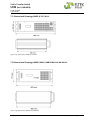
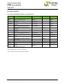
Pins (X3)
1
2
3
4
5
6
7
8
9
10
11
12
Function
UNB Output/Phase L1
UNB Output/Phase L1
UNB Output/Phase L1
n/c
n/c
n/c
n/c
n/c
n/c
n/c
n/c
n/c
©2012. Eltek Deutschland GmbH.
Eltek_UM_UNB_incl-WEB_E_R6.1.docx