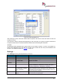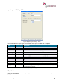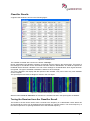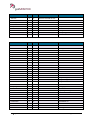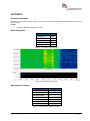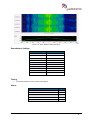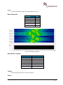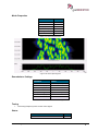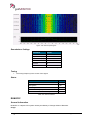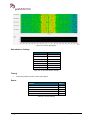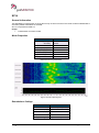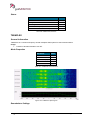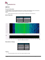
1
User Manual go2MONITOR 1.2 by PLATH AG, Switzerland Imprint PLATH AG Stauffacherstrasse 65 CH-3014 Bern Phone: +41 311 6446 www.go2signals.ch [email protected] All brand names in this document are trademarks or registered trademarks of their owners. © 2013 PLATH AG All rights, including those for translation, reserved. Reproduction in whole or in part in any form is prohibited without written consent of the copyright owner. Specifications are subject to change. All rights reserved Printed: 5 August 2013 Contents General 1 Welcome to go2MONITOR ..................................................................................... 1 go2SIGNALS........................................................................................................... 2 About us .................................................................................................................. 3 Revisions ................................................................................................................. 3 Setup 5 Installation ............................................................................................................... 5 Connecting the Dongle .........................................................................................12 License ..................................................................................................................12 Signal Sources ......................................................................................................12 Receiver Setup ........................................................................................13 Streaming Sources ..................................................................................16 Overview 19 Display ..................................................................................................................19 Signal Selection ....................................................................................................19 Production Channel ..............................................................................................19 Main Screen 21 Main Menu ............................................................................................................23 File Menu ..............................................................................................................23 Saving a Configuration .............................................................................23 Loading a Configuration ...........................................................................23 Modem List Editor ....................................................................................24 Settings….................................................................................................25 Views Menu...........................................................................................................26 Channel Processing .................................................................................27 Classification ............................................................................................27 Spectrogram Settings ..............................................................................27 Stations ....................................................................................................27 Help Menu .............................................................................................................27 Contents ...................................................................................................27 About ........................................................................................................27 Input Selection ......................................................................................................27 File Input ..................................................................................................28 Receiver Input ..........................................................................................29 Stream Input.............................................................................................30 Spectrum and Spectrogram ..................................................................................31 Overview ..................................................................................................31 Spectrogram Settings ..............................................................................32 Magnifier ..................................................................................................37 Classifier (Snapshot, Wideband) ..........................................................................38 General ....................................................................................................38 Classifier Results .....................................................................................41 Tuning the Receiver from the Classifier Result .......................................41 User Manual go2MONITOR 1.2 Contents iii Filter and Display Options ........................................................................42 Stations .................................................................................................................43 General ....................................................................................................43 Edit Stations .............................................................................................44 Add Stations .............................................................................................45 Database Directory ..................................................................................46 Options .....................................................................................................46 Tuning the Receiver directly from the List ...............................................47 Channel Window 49 General .................................................................................................................49 Delays ......................................................................................................49 Working with Multiple Channels ...............................................................50 Predefined Window Styles .......................................................................50 Channel Window Toolbar ......................................................................................52 Spectrogram Settings ...........................................................................................53 Parameters...............................................................................................53 Cursor ......................................................................................................55 Extras .......................................................................................................58 Frequency Control and Bandwidth ..........................................................59 Result Window ......................................................................................................59 Result Window Toolbar ............................................................................60 Save Decoder Result ...............................................................................60 Print ..........................................................................................................61 Wrap text ..................................................................................................61 Text Only ..................................................................................................62 Classification Mode ...............................................................................................62 General ....................................................................................................62 Classification Results ...............................................................................62 Dynamic Modem List ...............................................................................63 Decoding Mode .....................................................................................................64 General ....................................................................................................64 Modem Selection .....................................................................................64 Decoder List .............................................................................................65 Result Window .........................................................................................65 Recognition + Decoding Mode ..............................................................................65 General ....................................................................................................65 Modem Search .........................................................................................66 Classification + Recognition + Decoding Mode ....................................................66 Options 67 Option 1: Narrowband Receiver Control 4 Channels............................................67 Option 2: Wideband Classification 20 MHz ..........................................................67 Option 3: Automatic Monitoring and Tasking ........................................................67 Option 4: Multichannel Production 32 Channels ...................................................67 Option 5: Wideband Recording 20 MHz ...............................................................67 Technical Reference 69 WAV Files .............................................................................................................69 WAV Format.............................................................................................69 Extended WAV-Format with Custom Data ..............................................69 Tools ........................................................................................................74 bin, ver, txt and cmf Modem Description Files ......................................................75 ver files .....................................................................................................75 bin, txt Files ..............................................................................................77 cmf files ....................................................................................................78 iv Contents User Manual go2MONITOR 1.2 Station List CSV File .............................................................................................78 Specifications 81 System ..................................................................................................................81 Supported Receivers ............................................................................................81 Classifier ...............................................................................................................82 Demodulators ........................................................................................................83 Decoder List ..........................................................................................................84 Standard Decoders HF 91 Version History ......................................................................................................91 Available Decoders ...............................................................................................91 Alcatel 801H .............................................................................................91 ALIS .........................................................................................................93 ALIS-2 ......................................................................................................94 ARQ-6-90 .................................................................................................96 ARQ-6-98 .................................................................................................97 ARQ-E ......................................................................................................99 ARQ-E3 ..................................................................................................101 ARQ-M2-242 ..........................................................................................102 ARQ-M2-342 ..........................................................................................104 ARQ-M4-242 ..........................................................................................105 ARQ-M4-342 ..........................................................................................107 ARQ-N....................................................................................................108 ASCII 7 Bit..............................................................................................110 ASCII 8 Bit..............................................................................................111 AUTOSPEC ...........................................................................................113 Baudot async .........................................................................................114 Baudot sync ...........................................................................................116 BULG-ASCII ...........................................................................................117 CHU .......................................................................................................119 CIS-11 ....................................................................................................120 CIS-12 ....................................................................................................122 CIS-14 ....................................................................................................123 CIS-36 ....................................................................................................125 CIS-36-50 ...............................................................................................126 CIS 405-3915 .........................................................................................128 CIS-8181 ................................................................................................129 Clover-II..................................................................................................130 Clover 2000 ............................................................................................132 Codan 3012............................................................................................134 Codan Selcal ..........................................................................................136 Coquelet-8..............................................................................................138 Coquelet-13............................................................................................139 Coquelet-80............................................................................................141 DGPS .....................................................................................................142 DSC ........................................................................................................143 DUP-ARQ...............................................................................................145 FEC-A ....................................................................................................146 FSK 400/500 ..........................................................................................147 Globe Wireless FSK ...............................................................................149 Globe Wireless PSK ..............................................................................150 G-TOR....................................................................................................152 HFDL ......................................................................................................153 HNG-FEC ...............................................................................................155 MD674....................................................................................................156 User Manual go2MONITOR 1.2 Contents v MEROD ..................................................................................................157 MFSK8 ...................................................................................................158 MFSK16 .................................................................................................160 Morse .....................................................................................................161 Olivia ......................................................................................................162 Packet 300 .............................................................................................164 PACTOR I ..............................................................................................165 PACTOR I FEC ......................................................................................167 PACTOR II .............................................................................................168 PACTOR II FEC .....................................................................................169 PACTOR III ............................................................................................171 Piccolo MK6 ...........................................................................................172 Piccolo MK12 .........................................................................................174 POL-ARQ ...............................................................................................175 PSK10 ....................................................................................................176 PSK10-AM .............................................................................................178 PSK31 ....................................................................................................179 RUM-FEC...............................................................................................180 SI-ARQ ...................................................................................................182 SI-FEC ...................................................................................................183 SITOR-A.................................................................................................185 SITOR-B.................................................................................................186 SP14 ......................................................................................................188 SPREAD 51 ...........................................................................................189 SWED-ARQ ...........................................................................................190 TWINPLEX .............................................................................................192 Visel .......................................................................................................193 Standard Decoders VHF/UHF 195 Version History ....................................................................................................195 Available Decoders .............................................................................................195 ACARS VHF...........................................................................................195 AIS .........................................................................................................197 CCIR ......................................................................................................198 CCITT.....................................................................................................200 CTCSS ...................................................................................................201 DMR .......................................................................................................202 dPMR .....................................................................................................204 DSC ........................................................................................................205 EEA ........................................................................................................206 EIA .........................................................................................................208 Euro ........................................................................................................209 FLEX ......................................................................................................210 FMS-BOS ...............................................................................................212 Golay Pager ...........................................................................................213 MPT1327................................................................................................215 NATEL....................................................................................................216 NMT450 .................................................................................................218 POCSAG ................................................................................................219 TETRA ...................................................................................................220 Tetrapol ..................................................................................................222 VDEW ....................................................................................................223 VDL 2 .....................................................................................................224 VDL 3 .....................................................................................................226 ZVEI .......................................................................................................227 Premium Decoders vi Contents 229 User Manual go2MONITOR 1.2 Version History ....................................................................................................229 Installation ...........................................................................................................229 go2MONITOR / CMAS ...........................................................................229 go2DECODE / PROCEED .....................................................................231 Available Decoders .............................................................................................233 ALE-2G ..................................................................................................233 CHN 4plus4 ............................................................................................234 HC-ARQ .................................................................................................236 LINK 11 CLEW .......................................................................................237 LINK 11 SLEW .......................................................................................238 MIL-M-55529A .......................................................................................240 MIL-STD-188-110B 16Tone...................................................................241 MIL-STD-188-110B 39Tone...................................................................243 STANAG-4197 .......................................................................................244 STANAG-4285 .......................................................................................246 STANAG-4415 .......................................................................................247 STANAG-4481 .......................................................................................249 STANAG-4529 .......................................................................................251 STANAG-4539 .......................................................................................252 STANAG-4539 HDR ..............................................................................254 STANAG-5065 .......................................................................................254 Appendix 257 License terms ......................................................................................................257 Bug reporting.......................................................................................................258 Conditions of sale................................................................................................258 Glossary of Terms 261 List of Figures 267 List of Tables 271 Index 278 User Manual go2MONITOR 1.2 Contents vii General Welcome to go2MONITOR go2MONITOR is a modular software solution for receiver control, classification, demodulation, decoding and recording of LF, HF, VHF, UHF signals. Current wideband software defined radios (SDR) demand for a new generation of monitoring tools as complex monitoring systems should not be limited by the number of decoders. go2MONITOR is the perfect, none-intrusive signal monitoring solution for: Homeland and government, security agencies New threats demand superiority of information. Acquisition of information means gathering and analyzing information of all potential sources. In addition the increasing density of signals, the growing complexity and the use of new or modified modems are posing a challenge in which go2MONITOR assists the operator in his daily work by providing all the required tools and an easy to use user interface. The software provides the functions to record the spectrum for later analyzing and processing by more specialized tools and experts. Telecommunications authorities Identification and monitoring of new or existing signals is a main task of telecommunication authorities. Due to modern telecommunication systems this is no longer an easy work in standard manual operation. The automatic approach of go2MONITOR saves a lot of time and costs. COMINT, signal corps go2MONITOR is a standalone application and is perfectly suited for rapid reaction task forces and advanced commands. All that is required for monitoring are go2MONITOR, a laptop, a SDR and an antenna! System integrators A TCP/IP remote control interface is available for external applications and provides all the function required to integrate go2MONITOR into your application. Applications will be earlier on the market and do not bear the risk and costs of the development of an own software. go2MONITOR displays an overview of the signal scenario utilizing a spectrogram and a spectrum FFT. Various display settings, cursors, and a dynamic zoom are available. Features 1 MHz wideband input (spectrogram, Fast Fourier Transform (FFT), classifier) Automated classification and production using an extensive decoder library State-of-the-art GUI includes window pre-sets, drag & drop, and integrated station list Integrated receiver control with direct Software Defined Radio (SDR) interface Parallel processing of up to eight buffered Digital Down Conversion (DDC) production channels User Manual go2MONITOR 1.2 General 1 Decoder Description Language (DDL) support. Extend your decoder list without releasing any information Benefits Few lost or unidentified signals with a high number of produced signals Fast reaction to modified modems Keep the knowledge in your organization High order of automation go2SIGNALS The use of radio communication is constantly rising. The traditional approach of monitoring this more and more connected signal scenario with a manual approach of channel stepping and manual search is not promising for future challenges. The product line go2SIGNALS covers customer requirements from traditional manual signal handling to fully automatic intelligence system. This provides processing speed and user comfort of automatic intelligence systems to single user working positions. It is the perfect solution for mobile, stand-alone and remote controlled applications as well as a start into the world of automatic monitoring. The focus of go2SIGNALS is on radio monitoring. Future products will also contain some parts of Communications Intelligence (COMINT) or Signal Intelligence (SIGINT). go2MONITOR is a modular software solution for receiver control, classification, demodulation, decoding and recording of HF, VHF, UHF signal. go2DECODE is a standalone software for signal recognition, demodulation, decoding, speech detection, signal recording and technical signal analysis. go2ANALYSE is a bit stream analysis software for manual determination of code characteristics. 2 General User Manual go2MONITOR 1.2 go2RECORD is a powerful integrated solution for monitoring, recording and extraction of wideband signal scenarios in a user-friendly and interactive way. About us PLATH AG (formerly PLATH Procitec Suisse AG - PPS AG) was founded in 2006. The main intention was building up software development expertise and getting closer to the Swiss market. By now PLATH AG also provides systems and services to international markets. The portfolio of the PLATH AG focuses on the challenges in the business of information and communication technologies. As system developers and integrators and in cooperation with our industrial partners, we jointly supply complete system solutions in the sector of IT and communications engineering. We see the biggest challenges in customer specific software and system development as well as in a structured and efficient project management for customers with high demands of quality. Additionally PLATH AG supplies further services in the field of system installation, maintenance and consulting. Revisions Release 1.2 Date Editor History 2013-04-01 Rha/MBu First release Added content: - maw files - Licensing - bin, txt, ver - cmf - wavetxt 2013-04-24 MBu Chapter “Start the Application” renamed to “Signal Sources “ and reorganized 2013-05-25 RHa Added content: - Specifications - Install Premium Decoder User Manual go2MONITOR 1.2 General 3 Setup Installation This chapter describes the installation on a computer with Windows 7 operating system. For the installation of the application go2MONITOR you need the installation data carrier (DVD, USB-Memory, ZIP file, etc.) with the required files from PLATH AG. During the installation the application and the WiBuKey driver are installed. If the installation of the dongle is not started automatically, locate the WiBuKey_Runtime folder on the installation data carrier and install the WiBuKey driver manually. Insert the installation DVD into drive of your computer and start the Setup.exe. Important: Old Versions must not be uninstalled as new versions will be installed in a new directory. Follow the installation wizard as described in the following figures: Figure 1: Welcome Screen of the Installation Assistant Read the text in the dialog and press <Next>. User Manual go2MONITOR 1.2 Setup 5 Figure 2: License Agreement Please read the license agreement and select I accept the terms in the License Agreement and click on <Next>. Figure 3: File Location Check whether the installation location is correct. If necessary, browse for a different location and click on <Next>. 6 Setup User Manual go2MONITOR 1.2 Figure 4: Standard Installation Click on <Install> to continue the installation. The WibuKey installation starts automatically. Depending on the language setting of your operating system the language in the following dialogs may vary. Figure 5: WibuKey Setup Read the text and click on <Next>. User Manual go2MONITOR 1.2 Setup 7 Figure 6: Select Language for WibuKey Select the required languages and click on <Next>. Figure 7: Select Installation Folder Specify the target directory for the WibuKey tools and click on <Next>. If the folder does not exist, the following message is displayed: Figure 8: Create New Folder for WibuKey Installation Accept to create the required folder with <Yes>. 8 Setup User Manual go2MONITOR 1.2 Figure 9: Select WibuKey Components Click on <Next> to continue the installation. Figure 10: WibuKey Installation Tasks Accept the installation tasks with a click on <Next>. User Manual go2MONITOR 1.2 Setup 9 Figure 11: Confirmation Installation Tasks Finished After all tasks have been finished, click on <Next>. Figure 12: WibuKey Installation Finished The WibuKey installation is now complete. In this last dialog select if you want to read the help file. Click on <Finish>. 10 Setup User Manual go2MONITOR 1.2 Figure 13: Help File of the WibuKey and Confirmation of Successful Installation Click on <OK> to continue with the installation of the application. Figure 14: Progress of go2MONITOR Installation User Manual go2MONITOR 1.2 Setup 11 After successful installation the setup assistant displays the following message: Figure 15: Successful Installation of the Application go2MONITOR Click on <Finish> to exit the setup. Connecting the Dongle Once the installation is finished connect the dongle you received to an USB port. In case the dongle has already been connected, remove it from the port and reconnect. You can run the application go2MONITOR only with a connected dongle. License The dongle is part of the software’s copy-protection. Through the combination of an USB-dongle and a license-file the application can be installed on more than one PC, but can at a given time run only on the PC to which the dongle is connected. A key is coded into the Wibu-dongle. The license file, with the extension maw, holds information about the functionality which is available due to the license paid. It has to be installed on each PC on which the application is supposed to run. At run-time, the application compares the information coded into the licensefile with the dongle and unblocks the selected software if they are consistent. The license-file default.maw is located in the go2MONITOR-related subfolder of the user directory. C:\Users\<your user name>\go2SIGNALS\go2MONITOR v.n\default.maw Signal Sources This chapter describes the necessary configurations to use external receivers or streams as an input for go2MONITOR . Alternatively recordings can be played back for off-line signal processing. We recommend to use recorded files (provided by go2SIGNALS) to get familiar with the software. 12 Setup User Manual go2MONITOR 1.2 Receiver Setup Receivers are controlled by the Receiver Control Module (RCM). The configuration takes place in the receiver.conf file. For the list of receivers supported by go2MONITOR see: Supported Receivers. The default receiver.conf file is located as a read-only file in the go2MONITOR installation directory, e.g.: C:\Program Files (x86)\go2SIGNALS\go2MONITOR It is not used by the software and should never be edited. It is copied to the user directory during the first program start or if the file is is missing. It can be used to restore the original state in the user directory if needed. Configuration The receiver.conf file used by the application is located in the user directory of the current go2MONITOR installation, i.e.: c:\Documents and Settings\<your user name>\go2SIGNALS\go2MONITOR --or-C:\Users\<your user name>\go2SIGNALS\go2MONITOR The configuration is stored in a XML-file. It can be edited with a text editor, but be carefull as the correct XML-syntax must be kept. Attention: We strongly recommend an XML editor, like Notepad++ or Notepad2, to avoid errors, since XML editors apply syntax highlighting and checking! In the file some keys can be edited to enable or disable the support for certain receivers or to define receiver parameters like IP-address, control port etc. After making changes in the configuration file, restart go2MONITOR to apply the new settings. The receiver.conf contains a sample configuration for each supported receiver. Only the first receiver in the default list is enabled, all other receivers are commented out and therefore inactive. To use a specific receiver you have to uncomment the corresponding section in the file. Commented sections start with: <!-Commented sections end with: --> To enable the selected receiver, uncomment the related section. To do so, either remove both start and end comment markers, or extend both markers so that each forms a string which combines both markers, that is “<!---->“, exactly 4 hyphens! User Manual go2MONITOR 1.2 Setup 13 Figure 16: Commented WiNRADiO-Receiver The configuration of a single receiver always starts with <Receiver000> and ends with </Receiver000>. The receiver (WiNRADiO-G31DDC) in the preceding screenshot is commented out as it is surrounded by the comment markers. The following figure shows an active IZT-receiver and inactive EM100 and Perseus receivers in short form. 14 Setup User Manual go2MONITOR 1.2 Figure 17: Example Receiver Configuration Remove the comment markers from the receiver section you wish to use. Attention: Do not forget to comment the receiver which was active before! The following settings have to be changed in the file receiver.conf to adapt it to your specific receiver and its parameters. LAN receivers To connect to a receiver over LAN-interface you have to provide the IP-address and control port of the receiver (see below for GEW GRX-LAN exception). Consult the receiver handbook if you would like to know the default IP-address or change the IP-address of the receiver. Als0 check if DHCP is enabled and available. LAN Make sure that the receiver and the computer (running go2MONITOR) can communicate together. In case of problems try to ping the receiver from the computer. R&S EM100 Receiver The following line in the file receiver.conf : <add key="ComInterface" value="10.0.0.120" /> has to be changed to contain the local IP-address of the network interface where EM100 is connected (IP-address of the go2MONITOR computer). GRX-LAN Receiver The following block in the file receiver.conf has to be edited: <add0> <add key="ID" value="0"/> <add key="Name" value="IP_ADDRESS"/> <add key="Value" value="10.0.0.1"/> </add0> Instead of the “10.0.0.1” address, the actual IP-address of the receiver has to be entered. User Manual go2MONITOR 1.2 Setup 15 USB Receivers No further configuration is necessary for receivers with USB interface. Make sure that the USB-drivers are installed properly. Also check the connection between receiver and PC. Attention: Save the configuration file in your user directory after editing and restart go2MONITOR to apply your changes. Multiple Receivers It is possible to show multiple receivers in the input selector. To do so, all required <ReceiverXXX>…</ReceiverXXX> sections of the file receiver.conf have to be uncommented. Attention: The receiver numbers of all uncommented receiver sections (XXX number in <ReceiverXXX> tag) have to be changed to form a consecutive range, for example: <Receiver000> … </Receiver000> <Receiver001> … </Receiver001> <Receiver002> … </Receiver002> The following key has to be changed to contain the total number of used receivers: <add key="NumberOfReceivers" value="3" /> The following key has to be adapted to each receiver in use to provide a unique TCP-port. The receiver Receiver000 must use port 60301, Receiver001 must use port 60302 etc. <add key="PortCxZF" value="60301" /> Streaming Sources go2MONITOR can also use TCP/IP-based streams as its input. The supported format is compatible with other products available from the PLATH group. The streaming format description can be provided upon request. Stream configuration is setup in the file StreamInputs.conf. The default StreamInputs.conf file is located as a read-only file in the go2MONITOR installation directory, e.g.: C:\Program Files (x86)\go2SIGNALS\go2MONITOR It is not used by the software and should never be edited. It is copied to the user directory during the first program start or if the file is is missing. It can be used to restore the original state in the user directory if needed. Configuration The StreamInputs.conf file used by the application is located in the user directory of the current go2MONITOR installation, i.e.: 16 Setup User Manual go2MONITOR 1.2 c:\Documents and Settings\<your user name>\go2SIGNALS\go2MONITOR --or— C:\Users\<your user name>\go2SIGNALS\go2MONITOR The configuration is stored in a XML-file. It can be edited with a text editor, but be carefull as the correct XML-syntax must be kept. Again, we strongly recommend an XML editor, since these editors apply syntax highlighting and checking. This configuration file can be edited to add new sources or to change parameters like IP-address, port etc. After making changes in the configuration file, restart go2MONITOR to apply the new settings. The sample configuration file contains several examples for stream input from other applications: <?xml version="1.0" encoding="utf-8" ?> <configuration> <appSettings> <SignalInput_0> <add key="Type" value="STREAM" /> <add key="IP"value="127.0.0.1" /> <add key="Port" value="44001" /> <add key="DisplayName" value="go2DECODE/DANA stream" /> </SignalInput_0> <SignalInput_1> <add key="Type" value="STREAM" /> <add key="IP"value="127.0.0.1" /> <add key="Port" value="60100" /> <add key="DisplayName" value="go2RECORD stream" /> </SignalInput_1> </appSettings> </configuration> This configuration file defines two streaming sources in sections <SignalInput_0>...</ SignalInput_0> <SignalInput_1>...</ SignalInput_1> To add new streaming sources, add further tags: SignalInput_2, SignalInput_3,… Each SignalInput_X tag can contain the following parameters: <add key="Type" value="STREAM" />: mandatory, the type is always “STREAM” <add key="IP"value="127.0.0.1" />: mandatory, the IP address of the streaming source <add key="Port" value="60100" />: mandatory, the TCP port of the streaming source <add key="DisplayName" value="go2RECORD stream" />: mandatory, the descriptive name of the source which will be displayed in the GUI <add key="Cut" value="500000" />: optional, the effective bandwidth of the input signal User Manual go2MONITOR 1.2 Setup 17 Overview Display Signals are shown in two ways: The wideband spectrum display is the actual FFT of the frequency range under observation The wideband spectrogram shows the frequency occupation over a certain period (waterfall, sonogram) The wideband spectrum and spectrogram are configurable. Signal Selection Using the spectrum or spectrogram view the operator selects signals for further processing. For each selcted signal a Digital Down Conversion (DDC) applied. The output of a DDC is assigned to a production channel and the additional channel view displayed. Alternatively, the wideband classification results can be used to select signals of interest. Modulation, bandwidth, symbol rate, shift and other parameters are displayed for all classified signals within the wideband frequency range. Production Channel A production channel features a detailed display of the selected narrowband signal. The narrowband spectrum and spectrogram are configurable. A production channel provides different operating modes: Classification, the signal is continuously classified Decoding, the signals is decoded using a manually selected decoder Recognition and decoding, the signal will be decoded automatically using a modem list Classification, recognition and decoding, suitable decoders will be automatically selected depending on the classification result Depending on your license up to eight production channels can be used in parallel. The result view is configurable using XSLT (Extensible Style sheet Language Transformation). User Manual go2MONITOR 1.2 Overview 19 Main Screen Start the software either from the Windows Start menu or by double clicking the go2MONITOR program icon on the desktop. The software will come up with its main screen, the spectrum and the spectrogram. If the application was restarted, then the software will try to apply the settings in use when the application was stopped. Example: If the station list was available it will be opened again on the same position. The wideband spectrogram has the function of a control center for the software. The operator can control the receiver, select the signals and perform further analyses like classification or decoding on these signals with a simple double click. As a first step a rough classification on all signals within the selected bandwidth can be performed. Depending on the result, signals can be selected for decoding. In the following figure the screen is divided into the following parts: Menu bar with menu File, View and Help Control elements for spectrogram and spectrum Spectrogram and spectrum Receiver control Status bar at the bottom User Manual go2MONITOR 1.2 Main Screen 21 Figure 18: Main Screen with Spectrogram and Spectrum The functions of these menus will be described in the next chapters. Three status lights are located on the left side of the status bar at the bottom of the main screen. They give information about the input of a wideband signal. Light Meaning Error: No wideband signal or no input file available Waiting for signal Wideband signal available Table 1: Status of Signal Input The text field of the status bar on the bottom of the window displays information about the status of the software. If a receiver is connected, the settings of the receiver including the frequency range, total bandwidth and attenuation are displayed. 22 Main Screen User Manual go2MONITOR 1.2 Main Menu File Menu Saving a Configuration In the menu File/Save channel configuration the current settings can be stored in a configuration file. This file contains all parameters which have been setup in the channels like center frequency, bandwidth, mode, decoder list etc. For saving the configuration you have to enter a valid file name. The directory for the storage can be anywhere on the computer in use or on the network. Figure 19: Save Channel Configuration Loading a Configuration In the menu File/Load channel configuration the settings of a previously stored channel configuration can be loaded into go2MONITOR. The configuration file contains the information to setup the all the channels and their parameters like frequency, bandwidth, mode etc. Attention: The receiver has to operate within the correct frequency range which is defined in the receiver.conf file. Otherwise the status bar will display a message “frequency out of range”. As soon the receiver is tuned to the correct frequency, the wideband spectrum and spectrogram will start. Select the directory and the file where you saved the configuration and click <Open>. User Manual go2MONITOR 1.2 Main Screen 23 Figure 20: Load Channel Configuration Modem List Editor In the menu File/Modem list editor can be selected for creating and setting up specific modem lists. The modem list contains a selection of all modems which are available for the application. With the modem list editor, lists can be created, deleted or copied. Figure 21: Modem List Editor If you need to create a new list, click <New list…>. A new window opens and you can enter the name of the new list. 24 Main Screen User Manual go2MONITOR 1.2 Figure 22: Create New Modem List After entering the name, select the modems which required in the new list. Close the window to store the modems in the list. This function is useful to generate lists depending on the actual job or for groups of signals. Performance is improved if the search is restricted to MFSK modems when a MFSK signal is detected. ver Files All parameters (like displayed name, speed, shift etc.) are stored in specific *.ver files. The software retrieves these parameters from this XML file to build up the modem list and set up the demodulator and decoder. For additional details see “ver files” on page 75. Settings… In the Settings window general parameters can be set. Group Setting Description General Language Actually only English is supported Display text next to icons in main toolbar If enabled a text explaining the function of each icon is displayed in the toolbar. Default Mode Select the default mode to be used if if a new channel is opened. Available are: Classification, Decoding, Recognition + Decoding, Classification + Recognition + Decoding Automatic delay in “Classification + Recognition + Decoding” Automatically buffer the signal (delay) between the Spectrogram and the DDC channel. This gives you the chance to start the decoding from the beginning of the transmission even if you lost some time in the detection. Channel grid in spectrogram Grid used if you select a channel by double-click or by moving the center line in the spectrogram. Channels User Manual go2MONITOR 1.2 Main Screen 25 Group Decoder results Setting Description Font Select the font used for the text output (font, font style, size, effects and writing system). Reset Font Reset the font to Courier New, 8 Color Select the color used to mark the channel in the spectrogram Line width Select between single, double or triple width of the lines used to mark the channel in the spectrogram Default directory for recordings Select the directory where recordings are stored. Set to default Sets the recording path to the user directory Use generated file name Ask for the file name Choose between automatically generated file names (Date__frequency_bw) or if you like to define each time a filename. OK Accept all changes and close the window Set defaults Restore default settings Cancel Close window without saving. Channel markers Recordings Buttons Figure 23: Settings Window Views Menu From the menu Views different windows can be opened: 26 Main Screen User Manual go2MONITOR 1.2 Figure 24: Main Menu “Views” All views can be attached to the main window or be separated into a single window by drag-and-drop. For example in a two monitor system the channel window displaying 1, 4 or 8 channels can be moved to a second monitor. Channel Processing Display the channel window for narrowband classification, recognition, and decoding of waveforms. Classification Display the control and result window for the wideband classification Spectrogram Settings Display the control windows to set the parameter of the spectrogram and spectrum window Stations Display the station list. Help Menu Contents Contents provides help (user manual). About Display the About screen. Input Selection Figure 25: Input Selection Box All defined receivers and streaming sources are displayed in the dropdown menu of the toolbar field Input of the GUI (starting with the receivers, followed by the streaming sources and the file) and can be selected at any time. User Manual go2MONITOR 1.2 Main Screen 27 Figure 26: Input Selection File Input When selecting a File as input, the toolbar will provide functions according to the following figure. Figure 27: File Input Functions A mouse click on the button <Play File> opens the Add signal files dialog. Open Figure 28: Add Signal Files Menu You can select a wav file. If you press <Open>, the file is transferred into the internal input buffer. Wav File Drag-and-Drop You can load a .wav file by drag-and-drop. To do so, open the explorer, select a valid .wav file and drag it to the area of the progress bar. You can see the format of the mouse cursor change. If the + sign appears at the lower end of the arrow cursor you can drop the file. Playback will start immediately. The name of the file is displayed in the progress bar. 28 Main Screen User Manual go2MONITOR 1.2 Play File Toolbar When the .wav file is replayed the following functions are possible: Button Description A mouse click on the button Play File opens the Add signals dialog. The file will be played in a loop until the Stop button has been used. This button will pause the playback of the file. This button will stop the playback of the file and delete it from the memory This button will start the playback at the beginning of the file. With this dropdown box you can select which bandwidth of the recorded spectrum is used for the replay function. I.e. a value of 50% will reduce a bandwidth of 200 kHz to 100 kHz display bandwidth. With the slider between the spectrogram and spectrum you can move within the total frequency range of the replayed file. When playing back a file the time of the computer will be display on the left hand side of the spectrogram. A click on this button will take the time from the replayed file on the left side of the spectrogram This button will mirror the signal display. If there has been a carrier on the left side of the center frequency it will be moved to the right side of the center frequency. This function will help to display the correct spectrum and spectrogram when files have been recorded with a converter. Table 2: Functions File Replay Direct Jump to Position When the .wav file is played you can click to any position of the progress bar. The replay will start directly at the selected position of the bar. Receiver Input When selecting a receiver as input, the toolbar will provide functions according to the following figure. For the setup of additional receivers see “Receiver Setup” on page 13. Figure 29: Receiver Control Setting a Center Frequency The center frequency for a receiver can be entered directly as a value into the field Frequency. If a frequency has been entered into this field it is possible to tune the frequency in steps related to the selected bandwidth with the two arrows on the right side of the frequency field. The left arrow will tune the frequency to a lower value, the right arrow to a higher value. It is also possible to tune the frequency with the mouse wheel. For this function you have to place the mouse cursor on the right side of the digits. Moving the mouse wheel will also change the frequency up and down. Setting the Receiver Bandwidth The bandwidth of the overview spectrum can be set with the Bandwidth dropdown box. You will be provided different bandwidth values and can select one of them. User Manual go2MONITOR 1.2 Main Screen 29 Setting the Receiver Attenuation Strong signals close to the signal to be demodulated can cause intermodulation. To avoid this type of interference, the receiver input can be attenuated. Attenuation can be selected with the gain dropdown box. The range depends on the receiver. 0 dB corresponds to no attenuation, -30 dB corresponds to high attenuation. Selecting a Frequency for a Channel You can select any signal by a double click and transfer it to a channel. This is described in chapter “Spectrum and Spectrogram” on page 31. Stream Input When selecting a stream as input, the toolbar will provide no additional functions. For the setup of additional stream see “Streaming Sources” on page 16. TBD Figure 30: Stream Input 30 Main Screen User Manual go2MONITOR 1.2 Spectrum and Spectrogram Overview Figure 31: Spectrum and Spectrogram The window displays all the signals within the selected receiver bandwidth. The upper part displays the spectrum and the lower part the spectrogram. Moving the splitter between the two parts varies the ratio. Main functions can be called from the menu bar at the top of the window. Button Description This button will display frequency cursors for spectrum and spectrogram. The number of cursors and type is dependent on the setting in the spectrogram settings. This button will display two time cursors in the spectrogram window. This button will display two amplitude cursors in the spectrum window. When selecting the Zoom button the mouse cursor will change to a magnifier glass. You can move the magnifier to an interesting signal and click again. The selected frequency will be the new center frequency with the half bandwidth. If the total bandwidth of the spectrum or spectrogram is 100 kHz the result window will have a bandwidth of 50 kHz. A zoom out can only be done with the setting window. You can select a rectangle area of the spectrogram and press the Magnifier button. The selected area will be displayed in a new window. This button will pause the playback of the file. With this button the software will determine the best amplitude range for the spectrum and spectrogram. User Manual go2MONITOR 1.2 Main Screen 31 Button Description This button will open the settings window for the spectrum and spectrogram. This button will start a channel and add it to the channel window. The center frequency of the channel will be the center frequency of the main spectrum. This button will start a wideband recording of the received or replayed signal. An explorer view will open to name the recorded file. Figure 32: Explorer window for the recorded file Table 3: Toolbar Functions Spectrogram Settings With a right click in the spectrum or spectrogram window the context menu for the spectrogram settings is displayed. Figure 33: Spectrogram Settings – Context Menu 32 Main Screen User Manual go2MONITOR 1.2 The following settings are possible with the context menu: Context Menu Sub Menu Description Cursor X-Cursor Displays the amplitude cursors. Y-Cursor Displays the frequency cursors. The number of cursors is defined in the Spectrogram settings. Z-Cursor Displays the time cursors. The number of cursors is defined in the Spectrogram settings. 2 Cursor mode Two cursors are displayed. Harmonic All harmonic cursors will be displayed according the number of cursors specified in the Spectrogram settings. Mirrored All harmonic cursors will be displayed according the number of cursors specified in the Spectrogram settings on the left and right side of a center cursor. Centered Zoom Range Max. frequency range The maximum frequency range will be displayed in the spectrum view. Max. time range Max. time and frequency range Zoom in When selecting Zoom in the selected frequency will be the new center frequency with the half bandwidth. If the total bandwidth of the spectrum or spectrogram is 100 kHz the result window will have a bandwidth of 50 kHz. A zoom out can only be done with the setting window. Zoom out This menu item will reverse on Zoom in step. Immediate mouse zoom Mouse measure Move When selecting the menu item Move the spectrum can be dragged to the left or right side. Magnifier After selecting a rectangle area of the spectrogram with this menu item a new window will be opened displaying the selected area. Set channel 1 to this frequency When selecting this menu item the channel 1 will be displayed. The frequency under the mouse cursor will be the center frequency of the channel window. Set channel 2 to this frequency When selecting this menu item the channel 2 will be displayed. The frequency under the mouse cursor will be the center frequency of the channel window. Set channel 3 to this frequency When selecting this menu item the channel 3 will be displayed. The frequency under the mouse cursor will be the center frequency of the channel window. Set channel 4 to this frequency When selecting this menu item the channel 4 will be displayed. The frequency under the mouse cursor will be the center frequency of the channel window. Table 4: Context Menu Spectrogram User Manual go2MONITOR 1.2 Main Screen 33 Spectrogram Settings - Parameters Figure 34: Spectrogram Settings - Parameters In this window the parameters for the spectrogram can be set up. Parameter Description Maximum level Defines the maximum level of the display. Minimum level Defines the minimum level of the display. FFT length Number of values of frequency in which the signal is displayed. To get a higher resolution of the displayed frequency range, the FFT length should be increased. Exp. average The spectrum is displayed in average of several spectrums. The result of a change of the spectrum will be a total view of the spectrum. 0%: No average <80%: Low average 80% - 99%: High average 100%: No updating of the spectrum Windowing The FFT algorithm is used for the calculation of the spectrum. This algorithm indicates inaccuracies in the amplitude (attenuation) as well as in the bandwidth (expansion) of a signal due to the finite signal probe. These inaccuracies can be reduced using different windows. Lines / second Number of spectrums that can be calculated and displayed within one second. This parameter sets the time resolution for the spectrogram which is directly related to the scroll speed of the display. Pause In Pause, the display is stopped (not the signal processing). A change of parameters is possible for a more detailed analysis of the current signal. Auto range Automatic setting of the displayed range to view the total amplitude. Aggregation If activated the highest and average values are determined and displayed as a second curve in red color. Aggregation pause This check box will pause the aggregation 34 Main Screen User Manual go2MONITOR 1.2 Table 5: Spectrogram Settings - Parameters Spectrogram Settings - Cursor Figure 35: Spectrogram Settings - Cursor In this window the cursor functions can be set up.: Cursor Description X-Cursor The cursors are activated/deactivated in X-direction. They are used to measure frequencies in Hz. Cursor1 Frequency for cursor 1 Cursor2 Frequency for cursor 2 Diff. Cur. 1/2 Frequency distance between cursor1 and cursor2 Inv. diff. Inverted difference is a function for direct time readout according to the formula 1 / [value in box Diff. Cur. 1/2] Total diff. Frequency distance between the first and last cursor in 2 cursor mode, harmonic or mirror mode. Y-Cursor The cursors are activated/deactivated in Y-direction. They are used to measure the level of signals in db. Cursor1 Frequency for cursor 1 Cursor2 Frequency for cursor 2 Diff. Cur. 1/2 Frequency distance between cursor1 and cursor2 Total diff. Frequency distance between the first and last cursor in 2 cursor mode, harmonic or mirror mode. Z-Cursor The cursors are activated/deactivated in Z-direction. They are used to measure values of time. Cursor1 Time of cursor 1 Cursor2 Time of cursor 1 User Manual go2MONITOR 1.2 Main Screen 35 Cursor Description Diff. Cur. 1/2 Time difference between cursor 1 and 2 Inv. diff. Inverted difference is a function for direct frequency readout according to the formula 1 / [value in box. 1/2] Total diff. Time distance between the first and last cursor in 2 cursor mode, harmonic or mirror mode. 2 Cursor mode For measuring tasks two cursors are displayed at the same time. Harmonic With this button a specific number of cursors defined by the spin box Number at equidistant intervals in the area delimited by cursor1 and cursor2 are displayed. This mode makes it i.e. easy to measure the frequency distance for multi frequency signals like MFSK. Mirrored With this button a specific number of cursors defined by the spin box Number at equidistant intervals on the left and right side of cursor1 are displayed. The number off cursors should be odd. Cursor Mode Center Delta Number With this spin box the number of cursors is selected to be displayed in Harmonic or Mirror mode. Maximum Left Right Zoom in With enabled cursors, the button Zoom in permits to graphically zoom into the area delimited by the cursors. With disabled cursors, the zoom enlarges the area by a factor defined by the Relative factor in the Spectrogram settings of the total bandwidth around the center frequency. Additionally, a rectangle can be drawn in the display window and you zoom into this section graphically. Zoom out Each time the button Zoom Out is activated the Zoom in function is reversed. Pause In Pause, the display is stopped (not the signal processing). A change of parameters is possible for a more detailed analysis of the current signal. Auto range Automatic setting of the displayed range to view the total amplitude. Aggregation If activated the highest and average values are determined and displayed as a second curve in red color. Table 6: Spectrogram Settings - Cursor 36 Main Screen User Manual go2MONITOR 1.2 Spectrogram Settings - Extras Figure 36: Spectrogram Settings - Extra In this window different display types are selectable and the peak hold factor can be adjusted. Item Description Display Inverse This item enables the invers color display. Standard This item enables the standard color display. Monochrome This item enables the monochrome color display. Maximum This item aggregates the maximum values during aggregation time. Minimum This item aggregates the minimum values during aggregation time Average This item aggregates the average values during aggregation time Peak hold type Relative factor The relative factor is used for the zoom process to determine the zoom factor. Pause In Pause, the display is stopped (not the signal processing). A change of parameters is possible for a more detailed analysis of the current signal. Auto range Automatic setting of the displayed range to view the total amplitude. Aggregation If activated the highest and average values are determined and displayed as a second curve in red color. Table 7: Spectrogram Settings - Extra Magnifier After selecting a rectangle area of the spectrogram with this menu item a new window will be opened displaying the selected area. User Manual go2MONITOR 1.2 Main Screen 37 Figure 37: Magnifier Classifier (Snapshot, Wideband) General The snapshot classifier detects all emissions within the reception bandwidth. After the classification, the result list contains the following information Mode (Carrier, FSK2, MFSK, Morse, PSK, Voice, Unknown) Frequency Bandwidth Shift/Tone (Shift between carriers in a FSK or number of tones in a MFSK signal) Symbol rate SNR Time Stations (number of records in the stations database) 38 Main Screen User Manual go2MONITOR 1.2 The following figure shows the workflow of the classifier: Classification Unit Digital IF FFT Signal Detection Segmentation Classification Evaluation Delay Memory DDC Results Modulation Classification Figure 38: Classification Unit Signal Detection and Segmentation (Marked in yellow in Figure 38 on page 39) The input signal is transformed into the spectral domain by a Fast Fourier Transformation FFT. In the spectral domain all emissions and their parameter are determined. The following steps are executed cyclically: Noise level curve estimation Separation of noise and signal Center frequency and bandwidth measurement Energy distribution measurement Signal start and end time detection SNR measurement On-Air time and burst behavior measurement Detection of broadband interferences and elimination of errors in the result Time behavior for separation and combination of adjacent signals Rule-based merging of measured energy into emissions Definition of blocked-frequencies or ranges Automatic adaptation of detection parameters to the different frequency ranges (HF/VUHF) User Manual go2MONITOR 1.2 Main Screen 39 Energy detection Collect energy detection data for ~3s Merge energy detection results to Emissions Emission measuring Modulation type detection Spectrogram Pattern matching Send Emission information to the Control-Unit Figure 39: Steps within Classification Classification of Modulation (Marked in blue in Figure 38 on page 39) The determination of the type of modulation is done on each signal within a narrow band. The decision on which emissions are available and whether or not they are known is made here. If a measurement seems to be of interest the classification of modulation will be started. Buffering The input signal is stored in a buffer so that no part of the signal is lost during segmentation or classification. DDC All signals within the broadband signal are converted to narrow band signals by the software Digital Down Converter DDC. This way all signals are fragmented into smaller segments. Classification In this step common modulation types and modulation parameters are directly detected from the signal. Typical modems are classified by means of spectral pattern correlation. Additionally un-modulated carriers and sweepers are detected. Technical Parameters Classification specifications see “Classifier” on page 82. 40 Main Screen User Manual go2MONITOR 1.2 Classifier Results A typical result window is shown in the following figure: Figure 40: Classifier Result The classifier is started with a click on the button <Classify>. During classification the classifier is drawing a rectangle onto the signal in the spectrogram. The length of the rectangle is an indicator for the time which has been used for classification. The width is equal to the bandwidth which has been classified. The color of the rectangle is an identification which signal has been recognized. The type of classified modulation is written to each rectangle. The color is defined in the display and filter options of the classifier. They can be set to any color available on the computer. The spectrogram with these rectangles is shown in the next figure. Figure 41: Classifier Result Display in Spectrogram With the button Clear all emissions the results in the classifier list and in the spectrogram are deleted. Tuning the Receiver from the Classifier Result The results in the list can be used to tune a channel to the frequency of a classification result. With a left click and hold the record can be dragged and be released to a channel window. The center frequency of the channel spectrum or spectrogram will be set to the selected frequency. User Manual go2MONITOR 1.2 Main Screen 41 A right click will also open a context menu which provides all channels available in the software. From this list one channel can be selected. The center frequency of the selected channel spectrum or spectrogram will be set to the selected frequency. Filter and Display Options There are several options available which handle the work with the classifier. Show emission in spectrogram, classification will be started automatically when the receiver is tuned to a new center frequency. Pause spectrogram after each classification, the spectrogram display will be stopped after the classification is finished. Classify a new frequency range automatically, the classification should start automatically if the receiver center frequency is changed. Clear emissions before each new classification, the result list is cleared before a new classification is started. Display only emissions from the visible frequency range, show only the results from frequencies visible in the spectrogram. Classify automatically in time intervals, classifications can be done automatically all 10s, 20s or 30s. Select No to disable this function. The Line width can be set to single, double or triple. Figure 42: Classifier Options Show all, will enable all types of modulation Hide all, will disable all types of modulation. Load defaults will overwrite all color changes with the originally delivered color set. 42 Main Screen User Manual go2MONITOR 1.2 Stations General go2MONITOR has an integrated stations database. This database can store information about monitored signals. An optional and actual Klingenfuss Utility and Broadcast database is available from PLATH AG for import. The station database can be sorted by a click on the header of each column. The columns of the database and their contents are explained in the following table: Column Description Frequency The frequency of the dataset Station The name of the station or the usage for a frequency Modulation The used primary modulation like CW, USB, LSB, AM, FM or Digital and others Protocol The used protocol or name of the waveform Bandwidth The bandwidth of the signal Symbol rate The symbol rate of the protocol Callsign The call sign of the station Country (ITU) The country code according ITU Schedule The used time schedule when the station is on air. Comments Comment related to the station Date Date when the station has been stored in the database UID ID of the dataset Table 8: Elements of Station List In the Stations window, the comment of a selected record is displayed. Figure 43: Station List User Manual go2MONITOR 1.2 Main Screen 43 It is possible to select only a subset of datasets by performing a query to the list. The values are entered into the fields in the upper part of the window. These fields are described in the following table: Item Description Frequency range Enter a value into the from and to field Current frequency range Only frequencies from the selected receiver bandwidth are selected VLF ( 3-30 kHz) Frequencies in the VLF range from 3 kHz to 30 kHz are selected LF (30-300 kHz) Frequencies in the LF range from 30 kHz to 300 kHz are selected MF (300-3000 kHz) Frequencies in the LF range from 300 kHz to 3000 kHz are selected HF (3-30 kHz) Frequencies in the HF range from 3 MHz to 30 MHz are selected VHF (30-300 MHz) Frequencies in the VHF range from 30 MHz to 300 MHz are selected UHF (300-3000 MHz) Frequencies in the UHF range from 300 MHz to 3000 MHz are selected Modulation The field Modulation provides a selection of all used modulations in the database. By choosing a modulation only the selected one will be displayed in the list Protocol The field Protocol provides a selection of all used protocols in the database. By choosing a protocol only the selected one will be displayed in the list Station In the field Station a station name or parts of a name can be entered. All datasets in the column Station containing this name or the part of the name will be shown in the list. Table 9: Sort/Search Functions Station List Apply will add a filter to the table according to information in the search fields. It must be pressed to update the output. Reset will delete all search fields. Edit Stations Each record can be edited if new information is available. Edit will display the Edit station window. Edit is also available with the context menu available after a right-click on a station record. 44 Main Screen User Manual go2MONITOR 1.2 Figure 44: Edit Station The button <OK> will store the new or changed information in the database and close the window. <Cancel> will close the window without any changes. Add Stations A new station can be added to the database. Add will display the Add station window. Add is also available with the context menu available after a right-click on a station record. You can enter the new information in each field. At least a valid frequency should be given to the new record. User Manual go2MONITOR 1.2 Main Screen 45 Figure 45: Add Station The button <OK> will store the new information in the database and close the window. <Cancel> will close the window without any changes. Database Directory The software uses the station database available in the user directory \go2Signals\ go2MONITOR\station.db. All changes are stored in this file. If this file is not available, then the default database located in the program directory will be copied to the user directory. If no database is available in the program directory, then a new, empty database will be created in the user directory. Options The button <Options> will open a menu with additional functions. Delete Selected The selected datasets will be deleted, but are still available in the database. Delete All All datasets will be deleted, but are still available in the database. Show only Deleted Only deleted stations are displayed. 46 Main Screen User Manual go2MONITOR 1.2 Import and Export of Data If new station data are available from an external source these can be imported to the stations list. The station data have to be in a specific csv-file format with the “;” as separator. They are written to the file Station.db in the user directory. The contents of the station list can be exported to a comma separated csv-file. See “Station List CSV File” on page 78 for more details on the csv-file. To refresh the screen after an import, move the slider on the right. Figure 46: Import Station Data Tuning the Receiver directly from the List The datasets in the list can be used to tune a channel to the frequency of a station. Therefore the selection should contain only the stations within the receiver bandwidth. With a left click and hold the dataset can be dragged and be released to the channel window. The center frequency of the channel spectrum or spectrogram will be set to the selected frequency. User Manual go2MONITOR 1.2 Main Screen 47 Channel Window General The channel window makes it possible to process a single signal, this includes the classification, recognition and decoding. The signal can be selected in the spectrogram of the main screen by a double click or with the context menu (right–click). It will be transferred to the next free channel. If there is only one channel available this will be selected. Drag-and-drop of classifier results onto channel windows is also possible. The number of channels depends on the software version of go2MONITOR. The channel window provides four different working modes: Classification Decoding Recognition + Decoding Classification + Recognition + Decoding Figure 47: Channel Window Delays go2MONITOR provides the option to use a delay between selecting a signal in the main view until it will be displayed in the channel window. This delay can be set by the drop down box . Possible delay times are 5s, 10s and 15s. Clicking on the left part of the icon enables or disables the delay. User Manual go2MONITOR 1.2 Channel Window 49 Working with Multiple Channels Depending on the license go2MONITOR can display 1 to 8 channels at the same time. The following figure shows a version with four channels. Figure 48: Channel Window with Four Channels Predefined Window Styles In the channel view different display types can be applied. Each style changes the arrangement of window components. The figure below displays each channel in a different display style (from top to bottom: minimal view, horizontal view, vertical view). 50 Channel Window User Manual go2MONITOR 1.2 Figure 49: Predefined Window Styles Minimal View When channels are displayed in minimal view style, only the toolbar to control the channels is displayed. All other window components are hidden. Figure 50: Channels Displayed in Minimal View Style Horizontal View If a channel view is displayed in horizontal display style all components are displayed in one horizontal line. Tables might be displayed with a slide bar at the bottom if the table is too wide. User Manual go2MONITOR 1.2 Channel Window 51 Figure 51: Channel Displayed in Horizontal View Style Vertical View The channel view displayed in vertical style shows all columns of all tables and might need two rows. No slide bars below tables will be used, all table columns are displayed. Figure 52: Channel Displayed in Vertical View Style Channel Window Toolbar Button Description Views (See also chapter 0 Predefined Window Styles) Switch Auto range Spectrogram Settings (See also chapter 0 Spectrogram Settings) Exact Frequency Lock Signal Center Frequency Set channel in the current frequency range Set receiver to follow … Channel Bandwidth: Delays (see also chapter Delays). Mode selection Restart Processing Pause Processing 52 Channel Window User Manual go2MONITOR 1.2 Button Description Audio Squelch Demodulator Volume Add to Station List (see also chapter Add Stations) Matching Station Start Recorder Detach/Attach Channel Table 10: Channel Window Toolbar Spectrogram Settings Parameters Figure 53: Spectrogram Settings Channels - Parameters In this window the parameters for the spectrogram can be set up and it provides additional functions. Parameter Description Maximum level Defines the maximum level of the display. Minimum level Defines the minimum level of the display. FFT length Number of values of frequency in which the signal is displayed. To get a higher resolution of the displayed frequency range, the FFT length should be increased. Windowing The FFT algorithm is used for the calculation of the spectrum. This algorithm indicates inaccuracies in the amplitude (attenuation) as well as in the bandwidth (expansion) of a signal due to the finite signal probe. These inaccuracies can be reduced using different windowing. User Manual go2MONITOR 1.2 Channel Window 53 Parameter Description Lines/second Number of spectrums that can be calculated and displayed within one second. This parameter sets the time resolution for the spectrogram which is directly related to the scroll speed of the display. Pause In Pause, the display is stopped (not the signal processing). A change of parameters is possible for a more detailed analysis of the current signal. Auto range Automatic setting of the displayed range to view the total amplitude. Table 11: Spectrogram Settings Channels – Parameter Figure 54: Windowing 54 Channel Window User Manual go2MONITOR 1.2 Cursor Figure 55: Spectrogram Settings Channels - Cursors In this window the cursor functions can be set up. It provides also the function to zoom in and out to the display. Cursor Description X-Cursor The cursors are activated/deactivated in X-direction. They are used to measure frequencies in Hz. Cursor1 Frequency for cursor 1 Cursor2 Frequency for cursor 2 . 1/2 Frequency distance between cursor1 and cursor2 Inv. diff. Inverted difference is a function for direct time readout according to the formula 1 / [value in box. 1/2] Total diff. Frequency distance between the first and last cursor in 2 cursor mode, harmonic or mirror mode. Z-Cursor The cursors are activated/deactivated in Z-direction. They are used to measure values of time. Cursor1 Time of cursor 1 Cursor2 Time of cursor 1 . 1/2 Time difference between cursor 1 and 2 Inv. diff. Inverted difference is a function for direct frequency readout according to the formula 1 / [value in box. 1/2] Total diff. Time distance between the first and last cursor in 2 cursor mode, harmonic or mirror mode. 2 Cursor mode For measuring tasks two cursors are displayed at the same time. Harmonic With this button a specific number of cursors defined by the spin box Number at Cursor Mode User Manual go2MONITOR 1.2 Channel Window 55 Cursor Description equidistant intervals in the area delimited by cursor1 and cursor2 are displayed. This mode makes it i.e. easy to measure the frequency distance for multi frequency signals like MFSK. Mirrored With this button a specific number of cursors defined by the spin box Number at equidistant intervals on the left and right side of cursor1 are displayed. The number off cursors should be odd. Center Delta Number With this spin box the number of cursors is selected to be displayed in Harmonic or Mirror mode. Zoom in With enabled cursors, the button Zoom in permits to graphically zoom into the area delimited by the cursors. With disabled cursors, the zoom enlarges the area by a factor defined by the Relative factor in the Spectrogram settings of the total bandwidth around the center frequency. Additionally, a rectangle can be drawn in the display window and you zoom into this section graphically. Zoom out Each time the button Zoom Out is activated the Zoom in function is reversed. Pause In Pause, the display is stopped (not the signal processing). A change of parameters is possible for a more detailed analysis of the current signal. Auto range Automatic setting of the displayed range to view the total amplitude. Table 12: Spectrogram Settings Channels - Cursors Appearance of Cursors When operating with channels there are different appearances of cursors in the spectrogram. Whenever the channel is selected you will get two different line combinations. One display displays two wide and a weak dotted line. These are the search range and the center frequency for the signal. The weak dotted line can be moved within the spectrogram to select the center frequency of the signal. Both wide dashed d lines can also be moved towards the center line or away from it to set range that used to find the correct center frequency for decoding. Another display displays two fixed grey lines which are indicating the bandwidth of the signal as determined by the classifier. The distance of these lines will change as the result of the classifier depends on the signal quality. Figure 56: Channel Cursor 56 Channel Window User Manual go2MONITOR 1.2 Figure 57: Channel Cursor - Classification with Result When the classification process has finished with a result the color of line will change according to the colors defined in the classifier window. The name of the detected mode is written to these lines. Figure 58: Colors Classification Results When selecting one of the demodulators like USB or AM the bandwidth of this demodulator will be displayed in the channel view as a white transparent overlay. Figure 59: Channel View With Demodulator Bandwidth User Manual go2MONITOR 1.2 Channel Window 57 Extras Figure 60: Spectrogram Settings Channels – Extras In this window different display types and the relative factor can be adjusted. The display can be paused and be arranged to the signal levels. Item Description Display Inverse This item activates the invers color display. Standard This item activates the standard color display. Monochrome This item activates the monochrome color display. Relative factor The relative factor is used for the zoom process to determine the zoom factor. Pause In Pause, the display is stopped (not the signal processing). A change of parameters is possible for a more detailed analysis of the current signal. Auto range Automatic setting of the displayed range to view the total amplitude. Table 13: Spectrogram Settings Channel – Extras 58 Channel Window User Manual go2MONITOR 1.2 Frequency Control and Bandwidth Figure 61: Adjusting Frequencies and Display Bandwidth If necessary, the center frequency can be adjusted with the mouse by moving the center line of the signal or by entering a new frequency into the Center field. It is also possible to place the mouse cursor on the right side of a digit in the center field and to change the frequency with the mouse wheel. The total bandwidth of the channel spectrogram can be adjusted with the bandwidth field. It is possible to set the bandwidth to 2 kHz, 5 kHz, 10 kHz, 15 kHz, 20 kHz, 30 kHz and 50 kHz. This bandwidth will also be indicated at the signal in the main spectrogram. It is possible to listen to the signal in a channel window. The drop-down-box will open a context menu where the following demodulators can be selected: Demodulator Description USB Upper side band LSB Lower side band AM Amplitude modulation FM Frequency modulation Digital 1.8 kHz offset from the center frequency , bandwidth 3.6 kHz CW Continuous wave or morse with an offset of 800 Hz from the center frequency Off No audio output Output channel Audio output to the left, right or to both audio channels Table 14: Channel Window - Demodulators The bandwidth of each modulator will be displayed as an overlay in the channel spectrogram. Result Window When a production of output is started, then the decoded text this will be displayed in the result window. The most recent decoded text will also be displayed in the right part of the status bar. This has the advantage that in case of a minimized channel window the output of a decoder still can be monitored. User Manual go2MONITOR 1.2 Channel Window 59 Figure 62: Result Window Result Window Toolbar Button Description Output format selection XSLT setup Search text Clear Copy Save Decoder Results (see also chapter Save Decoder Result) Print: (see also chapter Print) Wrap text (see also chapter Wrap text) Text only (see also chapter Text Only) Table 15: Result Window Functions Save Decoder Result Results displayed in the decoder result window can be saved. Use the button <Save> to open an explorer window to define name and place of the file. 60 Channel Window User Manual go2MONITOR 1.2 Figure 63: Explorer Dialog to Save Decoder Results Print Decoder results currently displayed can be printed. Use the button <Print> to open the print dialog for your workstation. Define printer settings as usual. Figure 64: Print Dialog Wrap text This function changes the line break of the text. If the function is active (button has grey background) data is displayed within the window without a slide bar at the bottom. User Manual go2MONITOR 1.2 Channel Window 61 Figure 65: Decoder Results With Line Break (on the right) Text Only If the button <Text only> is activated all <new line> characters in the decoded result are interpreted as a real new line and will be replaced in the output window by a HTML line-break. For text output this selection may help reading clear text. In case of binary results the new line character may have another meaning and the replacement will cause errors in an additional processing-step. Classification Mode General The classification tool takes a probe of the signal and determines the possible type of modulation. By using the classification unit, it is possible to detect, measure and determine the modulation type for a signal in the currently available frequency range. The resulting information can be displayed in the GUI and used as an input to the further automatic or interactive processing. Figure 66: Classification Window with Result Classification Results The software measures several parameter of the signal probe. From these parameters the modulation of the signal will be determined. Additional the symbol rate is calculated. Depending on the type of modulation different parameters of the signal are displayed in the classification results. 62 Channel Window User Manual go2MONITOR 1.2 Dynamic Modem List According to the classification result the software will propose a selection of modems which may match the signal. This reduced list can be opened with the drop down box below the result window. All these modems are stored in a special list [ChX filtered by classification] which can be used further on when switching to the mode recognition or decoding. Figure 67: Dynamic Modem List The button on the right side of the dynamic modem list displays the number of possible modems in the list. By selecting this button the mode Recognition + Decoding will be opened containing the suggested modem list. Figure 68: Recognition + Decoding with Dynamic Modem List History Figure 69: Channel Classification – History View All classification results are stored in a history list which can be opened with the History tab. This list contains: Classification result with mode, probability, symbol rate and shift Bandwidth Signal to Noise Ratio SNR Time of recognition The list will be cleared when the application is stopped. User Manual go2MONITOR 1.2 Channel Window 63 Decoding Mode General In this mode the channel works as a decoder. From the modem list a modem can be selected. The decoded text will be displayed on the right side in the output window. Figure 70: Channel Mode Decoding Modem Selection From a drop-down-list, different modem lists e.g. for HF or VHF-UHF can be selected. See “Modem List Editor” on page 24 if you have to modify or add a new modem list. A modem is selected by a click on the modem row. The selected modem will turn to a green background color. Figure 71: Decoding of Signals Parameter Description Modem The name of the modem Status Used during recognition: Detecting Detection Detection status of modem: No result: Statement on modem status not possible Signal lost: Modem was detected but is lost Production: Modem is produced Modulation tracking: The modulation type has been detected, tracking parameters Modem tracking: The modem has been detected, tracking parameters 64 Channel Window User Manual go2MONITOR 1.2 Parameter Description Quality Quality of signal in % Decoder Status of the decoder: No sync: Decoder not detected Identified: Decoder has detected modem characteristics in the data stream Accepted: Decoder has been detected Sync: Modem has been detected Error: Decoder runtime error Symbol rate Measured symbol rate in Bd Shift Measured shift in Hz of a FSK signal Frequency Receiver center frequency of the signal Table 16: Decoder Status Decoder List From a drop-down-list, different modem lists, e.g. for HF or VHF-UHF, can be selected. New modem lists can be created in the File menu of the main screen. Result Window When the decoder starts with the production the result text will be written to the output window including a time stamp and a status. The most recently decoded text is additionally displayed in the status bar below the output window. Recognition + Decoding Mode General A production channel uses a configurable list of decoders and checks which of these decoders matches the signal. The signal is demodulated, decoded and the results are displayed in the result view. The decoder lists can be configured, loaded and saved. This way the operator can define specific decoders to be used according to the monitoring task. A previous classification enhances the production. go2DECODE (go2SIGNALS product for recognition, demodulation, analysis and decoding) can be used for analysis and creation of a new decoder, which can be used in go2MONITOR. Signals of interest can easily be added to an integrated station list. Entries in the station list can be assigned to production channels using drag & drop or the context menu. In this operation mode the software is searching for the correct modem within a modem list. The modem list can be selected from a drop-down-list and is displayed in the table. User Manual go2MONITOR 1.2 Channel Window 65 Figure 72: Recognition and Decoding of Signals Modem Search On starting the mode recognition and decoding, you will see that the spectrogram displays the signal in single frequencies (the figure shows a Baudot signal). In the result display, you will first see the modem search. The color of the modem in the list varies depending on the state of recognition (e.g. the Baudot line first turns yellow then green). This indicates that the signal has been recognized by the search routine. A moment later, the modem turns green and the decoded Baudot text is displayed in the pane showing the final results. For a list of all available modems see “Decoder List” on page 84. Classification + Recognition + Decoding Mode In this mode the following steps are executed sequentially: Classification of the signal Building a dynamic Modem list according to parameters of the classifier results Start the modem recognition If successful, starts the decoding of the signal otherwise restart from the beginning Figure 73: Classification, Recognition and Decoding of Signals 66 Channel Window User Manual go2MONITOR 1.2 Options Option 1: Narrowband Receiver Control 4 Channels TBD Option 2: Wideband Classification 20 MHz TBD Option 3: Automatic Monitoring and Tasking TBD Option 4: Multichannel Production 32 Channels TBD Option 5: Wideband Recording 20 MHz TBD User Manual go2MONITOR 1.2 Options 67 Technical Reference WAV Files WAV Format This subchapter describes the WAV file format extension for the storage of additional meta information which may be relevant for signals. The standard WAV file format is a RIFF-based format containing „fmt“ and “data” chunks. For the description of these chunks and the general RIFF format, please refer to “Multimedia Programming Interface and Data Specifications 1.0”. RIFF Chunk Descriptor fmt chunk data chunk Figure 74: Standard WAV-Format Extended WAV-Format with Custom Data The standard WAV format includes various meta information in the “fmt” chunk describing the signal. For the use in COMINT systems, additional information regarding signal time, signal frequency etc. have to be added. To store the information in the WAV file, an additional Meta chunk is added. The data in this chunk are stored in XML format. This additional chunk is ignored by standard tools which can process WAV files. User Manual go2MONITOR 1.2 Technical Reference 69 RIFF Chunk Descriptor fmt chunk data chunk meta chunk Figure 75: Extended WAV File Format The meta data chunk has the following structure: Length [Byte] Content Description 4 `meta` Header-signature 4 <length> Length of the meta-header XML Meta data in XML Table 17: Structure of the Meta Data 70 Technical Reference User Manual go2MONITOR 1.2 Figure 76: XML Schema XML Schema for the content of the meta data chunk: User Manual go2MONITOR 1.2 Technical Reference 71 <?xml version="1.0" encoding="UTF-8"?> <xs:schema xmlns:xs=http://www.w3.org/2001/XMLSchema elementFormDefault="qualified" tributeFormDefault="unqualified"> <xs:element name="signalinfo"> at- <xs:complexType> <xs:sequence> <xs:element name="base" type="baseType"/> <xs:element name="extended" type="extendedType" minOccurs="0" maxOccurs="1"/> <xs:element name="custom" type="customType" minOc- curs="0" maxOccurs="1"/> </xs:sequence> </xs:complexType> </xs:element> <xs:complexType name="customType"> <xs:sequence> <xs:any maxOccurs="unbounded" minOccurs="0" processContents="lax"/> </xs:sequence> </xs:complexType> <xs:complexType name="extendedType"> <xs:sequence> <xs:element name="antenna" type="xs:string" minOc- <xs:element name="receiver" type="xs:string" minOc- <xs:element name="comment" type="xs:string" minOc- curs="0"/> curs="0"/> curs="0"/> <xs:element name="location" type="locationDataType" <xs:element minOccurs="0" maxOccurs="unbounded"/> </xs:sequence> name="direction" type="directionDataType" minOccurs="0"/> </xs:complexType> <xs:complexType name="baseType"> <xs:sequence> <xs:element name="signaltime" type="xs:dateTime"/> <xs:element type="xs:positiveInteger" minOccurs="0"/> name="rf_frequency" <xs:element name="data_type" default="real"> <xs:simpleType> <xs:restriction base="xs:string"> <xs:enumeration value="real"/> <xs:enumeration value="complex"/> </xs:restriction> </xs:simpleType> </xs:element> <xs:element name="sample_rate" type="xs:double"/> <xs:element name="if_frequency" type="xs:double" minOccurs="1" default="0"/> </xs:sequence> </xs:complexType> <xs:complexType name="locationDataType"> <xs:sequence> <xs:element name="longitude" type="xs:double"/> <xs:element name="latitude" type="xs:double"/> <xs:element name="if_offset" type="xs:double"/> 72 Technical Reference User Manual go2MONITOR 1.2 <xs:element name="bandwidth" type="xs:double" minOc- curs="0"/> </xs:sequence> </xs:complexType> <xs:complexType name="directionDataType"> <xs:sequence> <xs:element name="dfsite" type="xs:string"/> <xs:element name="azimuth" type="xs:double"/> <xs:element name="if_offset" type="xs:double"/> <xs:element name="bandwidth" type="xs:double" minOc- curs="0"/> </xs:sequence> </xs:complexType> </xs:schema> The length of the meta data chunk must be a multiple of 4 bytes. The meta chunk will be added at the end of the WAV file to allow for adding the meta content without moving the data part of the WAV file. The format of the meta chunk contains three detail levels: base extended custom In the „base“ level, all elements important for the processing of the I/Q data file are stored: Element Description signaltime Time of the first sample in the file, UTC rf_frequency Receiver frequency in Hz data_type "real" or "complex" signal sample_rate Sampling rate (as floating point value) if_frequency IF-Frequency of the signal in Hz, always 0 for complex signals Table 18: Base Level of Meta Chunks In case of a complex (I/Q) signal, the WAV file must contain 2 channels. In the extended level, additional signal are stored: Element Description antenna Antenna description receiver Receiver description comment Free comment location Location information location/longitude Longitude (-180° … +180°) location/latitude Latitude (-90° … +90°) location/if_offset Offset relative to if_frequency, used for the location info location/bandwith Bandwidth around if_offset frequency, used for the location info direction One or multiple directions direction/dfsite Direction finder name direction/azimuth Direction azimuth (0-360°) direction/if_offset Offset relative to if_frequency, used for the direction info direction/bandwith Bandwidth around if_offset frequency, used for the direction info Table 19: Extended Level of Meta Chunks User Manual go2MONITOR 1.2 Technical Reference 73 The custom level contains any further user-defined fields. This is an example of the valid XML meta chunk content: <?xml version="1.0" encoding="utf-8"?> <signalinfo xmlns:xsi="http://www.w3.org/2001/XMLSchema-instance" xsi:noNamespaceSchemaLocation="signalinfo.xsd"> <base> <signaltime>2009-02-01T05:56:45.234Z</signaltime> <rf_frequency>6075000</rf_frequency> <data_type>real</data_type> <sample_rate>20000</sample_rate> <if_frequency>12500</if_frequency> </base> <extended> <antenna>Antenne 1</antenna> <receiver>EM010</receiver> </extended> </signalinfo> Tools wavetxt.exe The wavetxt application serves to provide the additional information required for the signal processing software if they are not contained in the wav file or if they are wrong. This additional txt-file can be generated with the application wavetxt.exe or be setup manually and must be stored together with the .wav file in the same directory. If you have a test.wav file then the associated txt-file is test.txt! The structure of the txt-file is: 0.0 COMPLEX 1 1) 10250 48000.00000 correct errors) 3631 38282000 0 // Comments // Signal-Number, File-Number (not required) // COMPLEX or REAL signal // Number of channels (not required, // Absolute frequency in Hz (not required, -1) // Sample rate (Hz) of the wav file (can be modified to // Preprocessing parameters (not required) The txt-file can be automatically generated with the application wavetxt.exe. The tool is normally started from the command line or from a batch file. Syntax: wavetxt [-cx|-re] [f=<frequency>] <input wave filename> Meaning: -cx, complex -re, real f= x, absolute receiver center frequency (required if the application should display the true signal frequency Example: wavetxt –cx f=10250 test.wav (will produce the structure above) Attention: Depending on the package the Visual Studio Redistributable Package vcredist_x86.exe or/and Qt-DLLs must be available in the same directory! 74 Technical Reference User Manual go2MONITOR 1.2 The sample rate needs not to be specified, as the value from the wav file will be used. Later you can modify the value to correct errors! bin, ver, txt and cmf Modem Description Files ver files A specific modem is characterized by the parameters which are stored in a XML-file with the extension ver. The ver-file holds a large number of parameters. Only a subset of them is required for a given modem, the spare ones are ignored. ver-files are located in the modem directory located in the user (highest priority) or the program directory. ver-files can either be generated/modified with a text or XML editor, or with an application like by go2DECODE. The basic structure of a ver-file is: <?xml version="1.0" encoding="utf-8" ?> <Modem version="1.0"> <tag>value</tag> <tag>value</tag> : <tag>value</tag> </Modem> Next follows an example, it is the ver-file for the Baudot modem with 50 Bd and 450 Hz shift. It is identified by its name : <Name>Baudot async 50Bd 450Hz</Name> The Baud-rate is 50 Bd: <BaudRate>50</BaudRate> The Baud-rate tolerance is 5 Bd: <BaudRateTolerance>5</BaudRateTolerance> The shift is 450 Hz : <Shift>450</Shift> The shift tolerance is 10 Hz : <ShiftTolerance>10</ShiftTolerance> The decoder is: <DecoderName>baudot115.bin</DecoderName> User Manual go2MONITOR 1.2 Technical Reference 75 <?xml version="1.0" encoding="utf-8" ?> <Modem version="1.0"> <ModemID>2069</ModemID> <Name>Baudot async 50Bd 450Hz</Name> <NameAbbr></NameAbbr> <ModemVersion>0</ModemVersion> <PrimaryModulationType>3</PrimaryModulationType> <DemodulatorType>4</DemodulatorType> <OffsetNominalFrequency>0</OffsetNominalFrequency> <MinSSOSearchFrequency>-500</MinSSOSearchFrequency> <MaxSSOSearchFrequency>500</MaxSSOSearchFrequency> <F7bMode>8</F7bMode> <CloverType>1</CloverType> <PactorType>0</PactorType> <BaudRate>50</BaudRate> <BaudRateTolerance>5</BaudRateTolerance> <BaudRate2>50</BaudRate2> <BaudRateTolerance2>5</BaudRateTolerance2> <ModulationOrder>2</ModulationOrder> <Shift>450</Shift> <ShiftTolerance>10</ShiftTolerance> <FSKModemType>2</FSKModemType> <GMSK_BT>-1</GMSK_BT> <ChanFiltDesignWindow>0</ChanFiltDesignWindow> <ChanFiltLength>0</ChanFiltLength> <ChanFiltBW>{0}</ChanFiltBW> <ChanFiltForm>{0}</ChanFiltForm> <ChanFiltAlpha>{0}</ChanFiltAlpha> <MomApplyMedian>1</MomApplyMedian> <MomFiltDesignWindow>0</MomFiltDesignWindow> <MomFiltLength>0</MomFiltLength> <MomFiltBW>{0}</MomFiltBW> <MomFiltForm>{0}</MomFiltForm> <MomFiltAlpha>{0}</MomFiltAlpha> <BurstMode>0</BurstMode> <BurstMinPauseDuration>0.100000001</BurstMinPauseDuration> <BurstMinDuration>0.100000001</BurstMinDuration> <BurstMaxDuration>1</BurstMaxDuration> <BurstMaxMeasDuration>0</BurstMaxMeasDuration> <BurstMinSNR>0</BurstMinSNR> <PSKVersion>1</PSKVersion> <Equalisation>0</Equalisation> <VNormType>0</VNormType> <ToneDuration>0.100000001</ToneDuration> <ToneDurationTolerance>0.00999999978</ToneDurationTolerance> <ToneNumber>2</ToneNumber> <ToneDistance>5</ToneDistance> <MarkToneFrequency>1400</MarkToneFrequency> <SpaceToneFrequency>1600</SpaceToneFrequency> <NumberOfChannels>2</NumberOfChannels> <ChannelPositioning>0</ChannelPositioning> <ChannelDistance>5</ChannelDistance> <SymbolTable>[1]</SymbolTable> <FrequencyList>{0}</FrequencyList> <DecoderID>1</DecoderID> 76 Technical Reference User Manual go2MONITOR 1.2 <DecoderID2>-1</DecoderID2> <DecoderName>baudot115</DecoderName> <DecoderNameAbbr></DecoderNameAbbr> <DecoderName2></DecoderName2> <DecoderNameAbbr2></DecoderNameAbbr2> <VoiceModulationType>0</VoiceModulationType> <VoiceDetectorSensitivity>0</VoiceDetectorSensitivity> <SELCALLType>0</SELCALLType> <KeyingRateType>3</KeyingRateType> <KeyingRate>250</KeyingRate> <KeyingRateTolerance>250</KeyingRateTolerance> <KeyingRate2>50</KeyingRate2> <KeyingRateTolerance2>0.100000001</KeyingRateTolerance2> <CarrierMeasureMode>0</CarrierMeasureMode> <PreCarrierPosition>1</PreCarrierPosition> <PreCarrierDuration>9.99999975e-06</PreCarrierDuration> <PrePreCarrierPosition>1</PrePreCarrierPosition> <PrePreCarrierDuration>9.99999997e-07</PrePreCarrierDuration> <PostCarrierPosition>1</PostCarrierPosition> <PostCarrierDuration>9.99999975e-06</PostCarrierDuration> <PostPostCarrierPosition>1</PostPostCarrierPosition> <PostPostCarrierDuration>9.99999997e-07</PostPostCarrierDuration> <FMBandwidth>7000</FMBandwidth> <Deemphasis>-1</Deemphasis> <FHSS_FreqResolution>-1</FHSS_FreqResolution> <FHSS_FreqDistance>-1</FHSS_FreqDistance> <FHSS_NumberOfFreqs>-1</FHSS_NumberOfFreqs> <OFDMNumberOfChannels>4</OFDMNumberOfChannels> <OFDMNumberOfSpecialChannels>0</OFDMNumberOfSpecialChannels> <OFDMChannelModulationType>11</OFDMChannelModulationType> <OFDMPhaseFirstChannel>0</OFDMPhaseFirstChannel> <OFDMPhaseRotationPerChannel>0</OFDMPhaseRotationPerChannel> <OFDMFrequencyFirstChannel>0</OFDMFrequencyFirstChannel> <OFDMFrequencyRotationPerChannel>0</OFDMFrequencyRotationPerChannel> <OFDMSpecialChannelIdx>{0}</OFDMSpecialChannelIdx> <OFDMSpecialChannelModulation>{0}</OFDMSpecialChannelModulation> <OFDMSpecialChannelPilotPhase>{0}</OFDMSpecialChannelPilotPhase> <OFDMSpecialChannelLevel>{0}</OFDMSpecialChannelLevel> <EnergyPatternDescription></EnergyPatternDescription> <ExtModemName></ExtModemName> <ExtModemMode></ExtModemMode> <ExtModemUsage>0</ExtModemUsage> <ExtProductionModemID>0</ExtProductionModemID> <AudioInWav>0</AudioInWav> </Modem> bin, txt Files Decoders are delivered in files with the extension bin. A binary file contains intermediate code which is processed by the APC of go2DECODE. The source-code for the decoder files is written in the decoder description language DDL, which is compiled into intermediate code. The ver-file provides the parameters for fine tuning of a specific modem. User Manual go2MONITOR 1.2 Technical Reference 77 go2MONITOR Decoder.txt Compiler Decoder.bin 00100111011 11000101001 10101011011 01110010110 10011101100 Text texttext Te 00100111011 11000101001 10101011011 01110010110 10011101100 Decoder.bin XML element element element Modem.ver Figure 77: Generation and Application of bin-Files The compiler and the standard decoder txt files are part of go2DECODE Standard. The additional debugger is part of go2DECODE Professional. Using txt files containing DDL has many advantages: Simple code as DDL contains powerful, optimized and specialized commands to process data communication Fast programming and testing No need to depend on people who are no members of your organization, program or modify your decoders without releasing proprietary information cmf files A XML-file which holds the information about the modem list setup in go2DECODE. These files are identified by the extension cmf and may not be edited! Station List CSV File Field Description Comment station_id Varchar Must contain an unique number Frequency Not empty, varchar In kHz Station Varchar Modulation Varchar code Varchar Bw Varchar Baudrate Varchar Callsign Varchar Lang Varchar ITU Varchar Schedule Varchar Service Varchar Settings Varchar Comments Varchar Src Varchar Date Varchar 78 Technical Reference Hz 01-Jan-2013 User Manual go2MONITOR 1.2 Field Description Comment Active Varchar Yes/No Delivered Varchar Yes/No UID Varchar Table 20: Stations List Fields for CSV Import and Export User Manual go2MONITOR 1.2 Technical Reference 79 Specifications System Parameter Specification Data acquisition Up to 1 MHz bandwidth Digital IF (complex baseband I/Q) Digital AF (complex WAV 8, 16, 32 Bit) RAW IF File Format Others on request Localization English Others on request Documentation Printed user manual / PDF Online-Help Recommended PC hardware CPU: Pentium IV, Multicore 2 GHz Memory: 4 GB RAM HDD: > 500 GB recommended (depends on recordings) Screen Resolution: >1920 x 1080 Pixel (multiple monitors recommended) Fast Ethernet for digital IF input OS Windows XP/7 Linux on request Supported Receivers The following receivers are supported by go2MONITOR: Receiver Interface Comment GEW GRX-LAN LAN See manual for IP-settings instructions IZT R30XX IZT R32XX IZT R33XX LAN Initialization of the receiver (start streaming to the specific IPaddress) has to be done by using IZT control software. Also, frequency and bandwidth has to be controlled by using IZT control software. See below for IP-settings instructions Microtelecom PERSEUS USB National Instruments ask Other generic “Winrad ExtIO” supported receivers Experimental support PLATH DBT 5400 + VDC ask R&S EB 200 ask R&S EM 510 ask R&S EM100 LAN RFSPACE SDR-14 USB User Manual go2MONITOR 1.2 See manual for IP-settings instructions Specifications 81 Receiver Interface RFSPACE SDR-IQ USB RTLSDR / Noxon USB-stick USB WiNRADiO WR-G31DDC USB/PCI WiNRADiO WR-G39DDC USB/PCI WJ 86XX ask WJ 87XX ask Comment Experimental support Table 21: List of Supported Receivers Classifier Technical Parameters Specification Max. signal bandwidth HF 20 kHz V/UHF 50 kHz Min. carrier to noise ratio 6 dB Recognition quality,(EB/No) for a detection rate >90% and false alarms <1% J3E LSB/USB, A3E AM, F3E NFM Morse 30-250 CPM FSK2 HF: 25-4800 Bd V/UHF: 1.2-25 kBd m = 0.5-10 11-15 dB FSK4 HF: 25-4800 Bd V/UHF: 1.2-25 kBd 11 - 15 dB MSK HF: 25-4800 Bd V/UHF: 1.2-25 kBd Multitone FSKn 3-200 ms (5-330 Bd) 5-64 tones 11-15 dB (D)PSK 2 A/B HF: 25-4800 Bd V/UHF: 1.2-25 kBd 7-10 dB A/B Decision: 8-10 dB (D)PSK 4 A/B HF: 25-4800 Bd V/UHF: 1.2-25 kBd 8-12 dB A/B Decision: 10-12 dB (D)PSK 8 A/B HF: 25-4800 Bd V/UHF: 1.2-25 kBd HF: 8-12 dB A/B Decision: 10-14 dB V-/UHF: 10-14 dB, A/B Decision: 12-14 dB Table 22: Technical Classification Parameters Parameter Description Car. x MFSK x Voic Pitch TBD x Type Type of voice like LSB, USB, AM , FM x Symbol rate The symbol rate in Bd Order The number of phase shifts x Version Version of PSK A or B x x x PSK The type of modulation and its probability x x CW Modulation 82 Specifications x FSK x Unkn x x User Manual go2MONITOR 1.2 Parameter Description Car. FSK MFSK CW PSK Voic Unkn CPM Transmitted character per minute x Dash Dot Ratio The ratio between the length of dashes and dots x Shift The measured shift Tone distance The measured distance between tones in Hz Frequency The receiver center frequency of the signal x x x x x x Bandwidth The overall bandwidth of the signal x x x x x x x SNR The signal to noise ratio in dB x x x x x x x Signal time Time of measurement x x x x x x x x x Table 23: Classifier Results Parameters Demodulators Demodulator Name A3E ASK2 ASK2PSK8 ASK4PSK8 CW DPSK 2, 4, 8 A/B F1A F3E F6 F7B FSK 2 matched filter FSK 2, 3, 4 GMSK J3E (USB, LSB) MDPSK 2, 4 MFSK 2 MPSK 2, 4 MSK Multitone (FSKn) OFDM OQPSK PSK2, 4, 8 A/B QAM 16, 32, 64, 128, 256 TFM3 Fast adaptive equalizer using known training sequences (via DDL) Primary demodulation SSB/AM/FM Table 24: Demodulator List User Manual go2MONITOR 1.2 Specifications 83 Decoder List Modem Det Prod Same as Modem File 2 channel ITA-2 RTTY X X F7B Morse/Baudot ACARS HF X X HFDL Alcatel 801H X - alcatel_801h.ver ALIS X X alis.ver ALIS 2 X - AMOR X X CIS-14 AMOR 96 X X CIS-14 AMTOR X X SITOR-A Annex-10 X X ICAO Selcal ARQ-1000 duplex X X ARQ-E/ARQ-N ARQ-28 X X ARQ-M2 242/ARQ-M4 242 ARQ-58 X X ARQ-M2 342/ARQ-M4 342 ARQ6-90 X X arq_6-90.ver ARQ6-98 X X arq_6-98.ver ARQ-E Cyc4 X X arq_e_cyc4_85bd_170hz.ver ARQ-E Cyc8 185Bd 370Hz X X arq_e_cyc8_185bd_370hz.ver ARQ-E Cyc8 96Bd 192Hz X X arq_e_cyc8_96bd_192hz.ver ARQ-E3 50Bd 400Hz X X arq_e3_50bd_400hz.ver ARQ-E3 100Bd 400Hz X X ARQ-M1 X X ARQ-M2-242 X X arq_m2_242_96bd_430hz.ver ARQ-M2-342 X X arq_m2_342_96bd_400hz.ver ARQ-M2-342 200Bd 410Hz X X arq_m2_342_200bd_410hz.ver ARQ-M4-242 X X arq_m4_242_192bd_173hz.ver ARQ-M4-342 X X arq_m4_342_192bd_400hz.ver ARQ-N X X arq_n.ver ARQ-SWE X X SWED-ARQ ARTRAC X X DUP-ARQ ASCII 7Bit X X ascii_7bit_100bd_173hz.ver ASCII 8Bit X X ascii_8bit_180bd_500hz.ver AUTOSPEC X X autospec.ver Baudot sync 200Bd 850Hz X X baudot_sync_200bd_850hz.ver Baudot sync 2 stopbit 50Bd 450Hz X X baudot_2stopbit_50bd_450hz.ver Baudot sync 2 stopbit 75Bd 500Hz X X baudot_2stopbit_75bd_500hz.ver Baudot async 1,5 Stopbit 50Bd 450Hz X X baudot_async_50bd_450hz.ver 84 Specifications alis2.ver arq_e3_100bd_400hz.ver ARQ-E3 User Manual go2MONITOR 1.2 Modem Baudot async 1,5 Stopbit 50Bd 170Hz Det X Prod Same as X Baudot F7B Modem File baudot_async_50bd_170hz.ver F7B Morse/Baudot BEE X X CIS-36-50 BF6 Baudot X X F7B Morse/Baudot BULG-ASCII X X CCIR 242 X X ARQ-M2 242/ARQ-M4 242 CCIR 342 X X ARQ-M2 242 CCIR 342-2 X X ARQ-M4 242 CCIR 476 A/B X X Sitor A/Sitor B CCIR 493-4 X X CODAN Selcal CCIR 518 Variant X X SWED-ARQ/ARQ690/ARQ6-98/POL-ARQ CCIR 519 Variant X X ARQ-E3 CHU X X CIS 10 11 11 X X CIS-11 X X cis-11.ver CIS-12 PSK2 X X cis-12_psk2.ver CIS-12 PSK4 X X cis-12_psk4.ver CIS-14 X X cis-14.ver CIS-20 X X CIS-36 X X cis-36.ver CIS-36-50 X X cis-36_50_50bd_250hz.ver CIS 405 3915 X X cis_405_3915.ver CIS 81 X X CIS 81-81 CIS 81-29 X X CIS 81-81 CIS-81-81 X X CIS AT3104 X X Clover II X X clover_II.ver Clover 2000 X X clover_2000.ver Clover 2000 Broadcast X X clover_2000broadcast.ver Clover 2500 X X clover_2500.ver Clover 2500 Broadcast X X clover_2500broadcast.ver CODAN 3012 Chirp X X codanchirp.ver CODAN Selcal X X codan_selcall.ver CODAN 3012 16 Channel PSK X X CODAN 3212 16 Channel PSK X X CODAN 8580 X X CODAN Selcal CODAN 9001 Chirp X X CODAN 3012 Chirp CROWD-36 X X CIS-36 Coquelet-13 X X coquelet-13_75ms.ver Coquelet-8 X X coquelet-8.ver User Manual go2MONITOR 1.2 bulg-ascii_75bd_510hz.ver chu_fsk.ver CIS 36 CIS-12 cis-81-81_81bd_500hz.ver CIS-12 codan3212_16channel_psk.ver Specifications 85 Modem Det Prod Same as Modem File Coquelet-8 FEC X X Coquelet-80 X X Coquelet-100 X X Alcatel 801H Coquelet-Mk1 X X Coquelet13 CW-Morse X X Morse DGPS X X dgps_200bd_msk.ver DSC-HF X X dsc-hf.ver DUP-ARQ X X dup-arq_125bd_170hz.ver FEC-A X X FEC12 X X Visel FEC 100 X X FEC-A FIRE X X CIS-12 Frost X X CIS 81-81 FROST1 X X CIS 405 3915 FSK 400/500 X - F7B Morse/Baudot X X F7B Morse X X f7b_baudot_morse.ver Globe Wireless FSK X X gw_fsk_100bd_200hz.ver Globe Wireless PSK X X Globe Wireless Pactor X X Globe Wireless FSK/PSK GMDSS X X DSC-HF G-TOR X X GW DATAPLEX X X HFDL PSK-2 X X hfdl_psk2.ver HNG-FEC X X hng_fec.ver Voice J3E - ICAO Selcal X X voice_j3e_selcal_icao.ver IRA-ARQ X X BULG-ASCII ITA-2 Twin X X F7B Morse/Baudot MD674 X X MERLIN X X MEROD X X merod.ver MFSK-8 X X mfsk-8.ver MFSK-16 X X mfsk-16.ver Morse X X morse_raw.ver MS5 X X CIS-12 NUM 13 X X SP 14 Olivia X X olivia-1000-32.ver Packet 300-4800 X X packet-300-4800.ver PACTOR I X X pactor_i.ver PACTOR I FEC X X pactor_i_fec.ver PACTOR II X X pactor_ii.ver PACTOR II FEC X X pactor_ii_fec.ver Golay 86 Specifications Coquelet-80 coquelet-80.ver fec-a_145bd_850hz.ver fsk_400_500.ver gw_psk_200bd_psk4.ver g-tor_300bd_180hz.ver G-TOR Globe Wireless FSK/PSK md674.ver ALIS User Manual go2MONITOR 1.2 Modem Det Prod Same as Modem File PACTOR III X X pactor_iii.ver PACTOR I/II/III X X pactor.ver Piccolo MK6 X X piccolo_mk6.ver Piccolo MK12 X X piccolo_mk12.ver Piccolo 6 X X Pol-ARQ X X Piccolo 12 X X PSK10 X X psk10.ver PSK-AM 10Bd X X psk-am_10bd.ver PSK31 X X psk31.ver PSK-AM 31Bd X X psk-am_31bd.ver PSK31-FEC X X psk31fec.ver PSK-AM 50Bd X X psk-am_50bd.ver PSK63 X X psk63-psk2.ver PSK63-FEC X X psk63_fec.ver PSK125 X X psk125_psk2.ver PSK125-FEC X X psk125_fec.ver PSK250 X X psk250.ver PSK220-FEC X X psk220_fec.ver QPSK31 X X qpsk31.ver QPSK63 X X QPSK125 X X QPSK250 X X RAC-ARQ X X MEROD RACAL-ARQ X X MEROD ROU-FEC X X RUM-FEC RS-ARQ X X ALIS RUM-FEC X X rum-fec_165bd.ver SI-ARQ X X si-arq.ver SI-FEC X X si-fec.ver SITOR-A X X sitor-a_170hz.ver SITOR ARQ X X SITOR-B 100Bd 170Hz X X sitor-b_100bd_170hz.ver SITOR-B 100Bd 400Hz X X sitor-b_100bd_400hz.ver SITOR FEC X X SP14 X X SPREAD 11 X X Autospec SPREAD 21 X X Autospec SPREAD 51 X X Saud-FEC X X SWED-ARQ X X T-600 X X CIS-36-50 TDM 242 X X ARQ-M2 242/ARQ-M4 242 User Manual go2MONITOR 1.2 Piccolo MK6 pol-arq_100bd.ver Piccolo MK12 SITOR-A SITOR-B sp14.ver spread51.ver RUM-FEC swed_arq.ver Specifications 87 Modem Det Prod Same as Modem File TDM 342 X X ARQ-M2 342/ARQ-M4 342 TDM 342 1 Channel X X ARQ-E3 TOR dirty X X Sitor B TORG 10/11 X X CIS-11 Twinplex X X twinplex.ver Visel X X visel.ver Voice A3E X X voice_a3e.ver Voice A3E/J3E X X voice_a3e_j3e.ver YUG-MIL X X Visel Table 25: HF Standard Decoders Modem Det Prod Same as Modem File AIS X X ais.ver ACARS VHF X X acars_vhf.ver CCITT X X ccitt.ver CCIR-1 X X ccir.ver CCIR-2 X X CityRuf X X CTCSS X X ctcss.ver DSC-VHF X X dsc-vhf.ver DMR X X dmr.ver dPMR X X dpmr.ver DZVEI X X EEA X X eea.ver EIA X X eia.ver EURO X X euro.ver EURO5 X X Flex 1600Bd FSK2 X X flex_1600bd_fsk2.ver Flex 1600Bd PSK2A X X flex_1600bd_psk2a.ver FMS-BOS X X fms_bos.ver GMDSS-VHF X X Golay Pager X X MPT1316 X X MPT1327 X X mpt1327_1200bd_msk.ver MODAT X X modat.ver NATEL X X natel.ver NMT450 X X nmt450.ver Packet 1200 X X Packet 9600 X X PCCIR X X CCIR-1 PDZVEI X X included in ZVEI POCSAG X X 88 Specifications ccir-2.ver POCSAG EURO DSC-VHF golay_pager.ver EEA Packet 300 packet9600.ver pocsag_1200bd.ver User Manual go2MONITOR 1.2 Modem Det Prod Same as Modem File PZVEI X x Tetra X X tetra.ver Tetrapol X - tetrapol.ver VDEW X X vdew.ver VDL 2 X X vdl2.ver VDL 3 X X vdl3.ver ZVEI X X zvei.ver ZVEI-1 X X included in ZVEI ZVEI-2 X X included in ZVEI ZVEI-3 X X included in ZVEI ZVEI FM Primary X X included in ZVEI zvei_fm.ver Table 26: VUHF Standard Decoders Modem Det ALE 2G X X ale.ver CHN 4+4 X - chn4plus4.ver Haegelin-Cryptos X X HC-ARQ X X LINK-11 CLEW X X LINK-11 SLEW X X STANAG 5511 SLEW MD 522 X X MIL-M-55529A MIL-188-110A ser. X X partly included in STANAG 4539/4415 MIL-188-110A App. C X X STANAG 4539 MIL-188-110B ser. X X partly included in STANAG 4539/4415 MIL-188-110B App.C X X partly included in STANAG 4539 HDR MIL-188-110 16 Tone X X mil188-110_16tone.ver MIL-188-110 39 Tone X X mil188-110_39tone.ver MIL-188-141A X X ALE(2G) MIL-188-141B X X ALE(2G) MIL-M-55529A X X mil-m-55529a.ver STANAG 4197 X X stanag4197.ver STANAG 4285 X X stanag4285.ver STANAG 4415 X X stanag4415.ver STANAG 4481 (FSK) X X stanag4481_fsk.ver STANAG 4481 (PSK) X X stanag4481_psk.ver STANAG 4529 X X stanag4529.ver STANAG 4539 X X stanag4539.ver STANAG 4539 HDR X X stanag4539-hdr.ver STANAG 5065 X X STANAG 5066 X X included in STANAG 4285 STANAG 5511 X X LINK11 CLEW User Manual go2MONITOR 1.2 Prod Same as Modem File HC-ARQ hc-arq.ver link-11_clew.ver link-11_slew.ver stanag_5065_fsk.ver Specifications 89 Modem Det Prod Same as STANAG 5511 SLEW X X LINK11 SLEW TADIL A X X LINK11 CLEW TADIL B X X LINK11 CLEW Modem File Table 27: Premium Decoders Note : For Premium decoders the source-code is not available. 90 Specifications User Manual go2MONITOR 1.2 Standard Decoders HF Version History Release 1.0 Date 2013-07-05 Editor MBu History Start Available Decoders Alcatel 801H General Information Alcatel-801H is an 8 tone MFSK ARQ teleprinter system. Usage: Transfer of textual information over HF. Mode Properties Parameter Value Modulation FSK Number of tones 8 Tone length (ms) 10 Tone spacing (Hz) 100 Table 28: Alcatel 801H Characteristics User Manual go2MONITOR 1.2 Standard Decoders HF 91 Figure 78: Alcatel 801H Spectrogram Demodulator Settings Parameter Default Demodulator Coquelet Tone duration (ms) 10 TD tolerance (ms) 0 No. of tones 8 Tone distance (Hz) 100 VER file name alcatel_801h.ver Table 29: Alcatel 801H Demodulator Settings Tuning The tuning frequency is the center of the signal. Status Feature Status Demodulation yes Recognition yes Decoding no Automatic Polarity Adjustment no Combination with other modems (modem list) yes Table 30: Alcatel 801H Features 92 Standard Decoders HF User Manual go2MONITOR 1.2 ALIS General Information ALIS is a simplex ARQ teleprinter system developed by Rhode & Schwarz. Usage: Transfer of textual information over HF with automatic Link setup. Mode Properties Parameter Value Modulation FSK Number of tones 2 Shift (Hz) 170 Symbol rate (Bd) 228.7 Error correction CRC-16 Alphabet ITA-2 Table 31: ALIS Characteristics Figure 79: ALIS Spectrogram Demodulator Settings Parameter User Manual go2MONITOR 1.2 Default Demodulator FSK 2,3,4 discr. Symbol rate (Bd) 228.67 SR tolerance (Bd) 1.000 Modulation order 2 Shift (Hz) 170 Shift tolerance (Hz) 10 Modem type Synchronous Min. burst length (s) 0.210 Max. burst length (s) 0.260 Standard Decoders HF 93 Parameter Default Min. pause length (s) 0.010 VER file name alis.ver Table 32: ALIS Demodulator Settings Tuning The tuning frequency is the center of the signal. Status Feature Status Demodulation yes Recognition yes Decoding yes Automatic Polarity Adjustment no Combination with other modems (modem list) yes Table 33: ALIS Features ALIS-2 General Information ALIS-2 is simplex ARQ teleprinter system developed by Rhode & Schwarz. ALIS-2 is a further development of ALIS. Usage: Transfer of textual information and binary data over HF with automatic Link setup. Mode Properties Parameter Value Modulation FSK Number of tones 8 Tone spacing (Hz) 240 Symbol rate (Bd) 240.82 Error correction CRC-16 Alphabet ITA-5 Table 34: ALIS-2 Characteristics 94 Standard Decoders HF User Manual go2MONITOR 1.2 Figure 80: ALIS-2 Spectrogram Demodulator Settings Parameter Default Demodulator Multitone (FSKn) Tone duration (ms) 4.153 TD tolerance (ms) 0.100 No. of tones 8 Tone position type Equidistant frequencies Tone distance (Hz) 240.816 Min. burst length (s) 0.040 Max. burst length (s) 0.350 Min. pause length (s) 0.070 VER file name alis2.ver Table 35: ALIS-2 Demodulator Settings Tuning The tuning frequency is the center of the signal. Status Feature Status Demodulation yes Recognition yes Decoding no Automatic Polarity Adjustment no Combination with other modems (modem list) yes Table 36: ALIS-2 Features User Manual go2MONITOR 1.2 Standard Decoders HF 95 ARQ-6-90 General Information ARQ-6-90 is an ARQ mode similar to SITOR for the exchange of teletype-data over a radio channel in a robust way. Usage: Basic data communication over HF. Mode Properties Parameter Value Modulation FSK Number of tones 2 Shift (Hz) 400 Bandwidth (Hz) 600 Symbol rate (Bd) 200 Error correction ARQ Alphabet CCIR-476 Table 37: ARQ-6-90 Characteristics Figure 81: ARQ-6-90 Spectrogram Demodulator Settings Parameter 96 Standard Decoders HF Default Demodulator FSK 2 matched Symbol rate (Bd) 200 SR tolerance (Bd) 5 Shift (Hz) 400 Shift tolerance (Hz) 20 Modem type Synchronous Min. burst length (s) 0.065 User Manual go2MONITOR 1.2 Parameter Default Max. burst length (s) 0.260 Min. pause length (s) 0.200 VER file name arq_6-90.ver Table 38: ARQ-6-90 Demodulator Settings Tuning The tuning frequency is the center of the signal. Status Feature Status Demodulation yes Recognition yes Decoding yes Automatic Polarity Adjustment yes Combination with other modems (modem list) yes Table 39: ARQ-6-90 Features ARQ-6-98 General Information ARQ-6-98 is an ARQ mode similar to SITOR for the exchange of teletype-data over a radio channel in a robust way. Usage: Basic data communication over HF. Mode Properties Parameter Value Modulation FSK Number of tones 2 Shift (Hz) 200 Bandwidth (Hz) 400 Symbol rate (Bd) 200 Error correction ARQ Alphabet CCIR-476 Table 40: ARQ-6-98 Characteristics User Manual go2MONITOR 1.2 Standard Decoders HF 97 Figure 82: ARQ-6-98 Spectrogram Demodulator Settings Parameter Default Demodulator FSK 2,3,4 discr. Symbol rate (Bd) 200 SR tolerance (Bd) 5 Modulation order 2 Shift (Hz) 170 Shift tolerance (Hz) 20 Modem type Synchronous Min. burst length (s) 0.065 Max. burst length (s) 0.260 Min. pause length (s) 0.150 VER file name arq_6-98.ver Table 41: ARQ-6-98 Demodulator Settings Tuning The tuning frequency is the center of the signal. Status Feature Status Demodulation yes Recognition yes Decoding yes Automatic Polarity Adjustment yes Combination with other modems (modem list) yes Table 42: ARQ-6-98 Features 98 Standard Decoders HF User Manual go2MONITOR 1.2 ARQ-E General Information ARQ-E is a synchronous dual channel ARQ mode for the exchange of teletype-data over a radio channel in a robust way. Usage: Military or diplomatic data communication over HF. Mode Properties Parameter Value Modulation FSK Number of tones 2 Shift (Hz) 170 / 370 Bandwidth (Hz) 300 / 600 Symbol rate (Bd) 30 … 650 Error correction ARQ Alphabet ITA-2 extended Table 43: ARQ-E Characteristics Figure 83: ARQ-E cyc4 Spectrogram User Manual go2MONITOR 1.2 Standard Decoders HF 99 Figure 84: ARQ-E cyc8 Spectrogram Demodulator Settings Parameter Default Demodulator FSK 2 matched Symbol rate (Bd) 85.7 185 SR tolerance (Bd) 4 5 Shift (Hz) 170 370 Shift tolerance (Hz) 20 Modem type Synchronous VER file name arq_e_cyc4_85bd_170hz.ver arq_e_cyc8_185bd_370hz.ver Table 44: ARQ-E Demodulator Settings Tuning The tuning frequency is the center of the signal. Status Feature Status Demodulation yes Recognition yes Decoding yes Automatic Polarity Adjustment yes Combination with other modems (modem list) yes Table 45: ARQ-E Features 100 Standard Decoders HF User Manual go2MONITOR 1.2 ARQ-E3 General Information ARQ-E3 is a synchronous dual channel ARQ mode for the exchange of teletype-data over a radio channel in a robust way. Usage: Military or diplomatic data communication over HF. Mode Properties Parameter Value Modulation FSK Number of tones 2 Shift (Hz) 400 Bandwidth (Hz) 600 Symbol rate (Bd) 30 … 650 Error correction ARQ Alphabet ITA-3 Table 46: ARQ-E3 Characteristics Figure 85: ARQ-E3 cyc8 Spectrogram Demodulator Settings Parameter User Manual go2MONITOR 1.2 Default Demodulator FSK 2 matched Symbol rate (Bd) 500 SR tolerance (Bd) 5 Shift (Hz) 400 Shift tolerance (Hz) 30 Modem type Synchronous VER file name arq_e3_50bd_400hz.ver Standard Decoders HF 101 Table 47: ARQ-E3 Demodulator Settings Tuning The tuning frequency is the center of the signal. Status Feature Status Demodulation yes Recognition yes Decoding yes Automatic Polarity Adjustment yes Combination with other modems (modem list) yes Table 48: ARQ-E3 Features ARQ-M2-242 General Information ARQ-M2-242 is a synchronous full duplex time-division multiplex system designed for low error-rate exchange of textual data between two stations of governmental authorities. Usage: Transfer of textual information over HF. Mode Properties Parameter Value Modulation FSK Number of tones 2 Shift (Hz) 430 Bandwidth (Hz) 600 / 800 Symbol rate (Bd) 96 / 200 Alphabet ITA-3 Table 49: ARQ-M2-242 Characteristics 102 Standard Decoders HF User Manual go2MONITOR 1.2 Figure 86: ARQ-M2-242 Spectrogram Demodulator Settings Parameter Default Demodulator FSK 2 matched Symbol rate (Bd) 96 SR tolerance (Bd) 5 Shift (Hz) 430 Shift tolerance (Hz) 30 Modem type Synchronous VER file name arq_m2_242_96bd_430hz.ver Table 50: ARQ-M2-242 Demodulator Settings Tuning The tuning frequency is the center of the signal. Status Feature Status Demodulation yes Recognition yes Decoding yes Automatic Polarity Adjustment no Combination with other modems (modem list) yes Table 51: ARQ-M2-242 Features User Manual go2MONITOR 1.2 Standard Decoders HF 103 ARQ-M2-342 General Information ARQ-M2-242 is a synchronous full duplex time-division multiplex system designed for low error-rate exchange of textual data between two stations of governmental authorities. Usage: Transfer of textual information over HF. Mode Properties Parameter Value Modulation FSK Number of tones 2 Shift (Hz) 400 Bandwidth (Hz) 600 / 800 Symbol rate (Bd) 96 / 200 Alphabet ITA-3 Table 52: ARQ-M2-342 Characteristics Figure 87: ARQ-M2-342 Spectrogram Demodulator Settings Parameter Default Demodulator FSK 2 matched Symbol rate (Bd) 96 SR tolerance (Bd) 5 Shift (Hz) 400 Shift tolerance (Hz) 30 Modem type Synchronous VER file name arq_m2_342_96bd_400hz.ver Table 53: ARQ-M2-342 Demodulator Settings 104 Standard Decoders HF User Manual go2MONITOR 1.2 Tuning The tuning frequency is the center of the signal. Status Feature Status Demodulation yes Recognition yes Decoding yes Automatic Polarity Adjustment no Combination with other modems (modem list) yes Table 54: ARQ-M2-342 Features ARQ-M4-242 General Information ARQ-M4-242 is a synchronous full duplex time-division multiplex system designed for low error-rate exchange of textual data between two stations of governmental authorities. Usage: Transfer of textual information over HF. Mode Properties Parameter Value Modulation FSK Number of tones 2 Shift (Hz) 170 Bandwidth (Hz) 400 Symbol rate (Bd) 172 / 192 Alphabet ITA-3 Table 55: ARQ-M4-242 Characteristics User Manual go2MONITOR 1.2 Standard Decoders HF 105 Figure 88: ARQ-M4-242 Spectrogram Demodulator Settings Parameter Default Demodulator FSK 2,3,4 discr. Symbol rate (Bd) 192 SR tolerance (Bd) 2 Modulation order 2 Shift (Hz) 173 Shift tolerance (Hz) 10 Modem type Synchronous VER file name arq_m4_242_192bd_173hz.ver Table 56: ARQ-M4-242 Demodulator Settings Tuning The tuning frequency is the center of the signal. Status Feature Status Demodulation yes Recognition yes Decoding yes Automatic Polarity Adjustment yes Combination with other modems (modem list) yes Table 57: ARQ-M4-242 Features 106 Standard Decoders HF User Manual go2MONITOR 1.2 ARQ-M4-342 General Information ARQ-M4-342 is a synchronous full duplex time-division multiplex system designed for low error-rate exchange of textual data between two stations of governmental authorities. Usage: Transfer of textual information over HF. Mode Properties Parameter Value Modulation FSK Number of tones 2 Shift (Hz) 400 Bandwidth (Hz) 800 Symbol rate (Bd) 172 / 192 Alphabet ITA-3 Table 58: ARQ-M4-342 Characteristics Figure 89: ARQ-M4-342 Spectrogram Demodulator Settings Parameter Default Demodulator FSK 2 matched Symbol rate (Bd) 192 SR tolerance (Bd) 5 Shift (Hz) 400 Shift tolerance (Hz) 10 Modem type Synchronous VER file name arq_m4_342_192bd_400hz.ver Table 59: ARQ-M4-342 Demodulator Settings User Manual go2MONITOR 1.2 Standard Decoders HF 107 Tuning The tuning frequency is the center of the signal. Status Feature Status Demodulation yes Recognition yes Decoding yes Automatic Polarity Adjustment yes Combination with other modems (modem list) yes Table 60: ARQ-M4-342 Features ARQ-N General Information ARQ-E is a synchronous dual channel ARQ mode. This system was used by Italian diplomatic services. Usage: Transfer of textual information over HF. Mode Properties Parameter Value Modulation FSK Number of tones 2 Shift (Hz) 850 Symbol rate (Bd) 96 Error correction ARQ Repetition cycles (char) 4,5,8 Alphabet ITA-2P Table 61: ARQ-N Characteristics 108 Standard Decoders HF User Manual go2MONITOR 1.2 Figure 90: ARQ-N Spectrogram Demodulator Settings Parameter Default Demodulator FSK 2 matched Symbol rate (Bd) 96 SR tolerance (Bd) 5 Shift (Hz) 850 Shift tolerance (Hz) 20 Modem type Synchronous VER file name arq_n.ver Table 62: ARQ-N Demodulator Settings Tuning The tuning frequency is the center of the signal. Status Feature Status Demodulation yes Recognition yes Decoding yes Automatic Polarity Adjustment yes Combination with other modems (modem list) yes Table 63: ARQ-N Features User Manual go2MONITOR 1.2 Standard Decoders HF 109 ASCII 7 Bit General Information The American Standard Code for Information Interchange (ASCII) is a set of binary values to represent printable characters in electronic communication. In the first version of the standard the character-length was 7 bit. Usage: Transfer of textual information over HF. Processing, transfer and storage of textual information. Mode Properties Parameter Value Modulation FSK Number of tones 2 Shift (Hz) 173 Bandwidth (Hz) 300 Symbol rate (Bd) 100 Character 1 Start-, 7 Data-, 1 Stop-Bit Table 64: ASCII 7 Bit Characteristics Figure 91: ASCII 7 Bit Spectrogram Demodulator Settings Parameter 110 Standard Decoders HF Default Demodulator FSK 2 matched Symbol rate (Bd) 100 SR tolerance (Bd) 5 Shift (Hz) 173 Shift tolerance (Hz) 10 Modem type Synchronous User Manual go2MONITOR 1.2 Parameter Default VER file name ascii_7bit_100bd_173hz.ver Table 65: ASCII 7 Bit Demodulator Settings Tuning The tuning frequency is the center of the signal. Status Feature Status Demodulation yes Recognition yes Decoding yes Automatic Polarity Adjustment no Combination with other modems (modem list) yes Table 66: ASCII 7 Bit Features ASCII 8 Bit General Information The American Standard Code for Information Interchange (ASCII) is a set of binary values to represent printable characters in electronic communication. In a later version of the standard the character-length was extended to 8 bit. Usage: Processing, transfer and storage of textual information. Mode Properties Parameter Value Modulation FSK Number of tones 2 Shift (Hz) 492 Bandwidth (Hz) 700 Symbol rate (Bd) 150 Character 1 Start-, 8 Data-, 2 Stop-Bit Table 67: ASCII 8 Bit Characteristics User Manual go2MONITOR 1.2 Standard Decoders HF 111 Figure 92: ASCII 8 Bit Spectrogram Demodulator Settings Parameter Default Demodulator FSK 2 matched Symbol rate (Bd) 180 SR tolerance (Bd) 90 Shift (Hz) 500 Shift tolerance (Hz) 10 Modem type Synchronous VER file name ascii_8bit_180bd_500hz.ver Table 68: ASCII 8 Bit Demodulator Settings Tuning The tuning frequency is the center of the signal. Status Feature Status Demodulation yes Recognition yes Decoding yes Automatic Polarity Adjustment no Combination with other modems (modem list) yes Table 69: ASCII 8 Bit Features 112 Standard Decoders HF User Manual go2MONITOR 1.2 AUTOSPEC General Information Autospec is a synchronous FEC system. This system was used by British coastal station for communication to oil rigs. Usage: Transfer of textual information over HF. Mode Properties Parameter Value Modulation FSK Number of tones 2 Shift (Hz) 270 Symbol rate (Bd) 68.5 Alphabet ITA-2 Table 70: AUTOSPEC Characteristics Figure 93: AUTOSPEC Spectrogram Demodulator Settings Parameter Default Demodulator FSK 2 matched Symbol rate (Bd) 68.5 SR tolerance (Bd) 1 Shift (Hz) 270 Shift tolerance (Hz) 10 Modem type Synchronous VER file name autospec.ver Table 71: AUTOSPEC Demodulator Settings User Manual go2MONITOR 1.2 Standard Decoders HF 113 Tuning The tuning frequency is the center of the signal. Status Feature Status Demodulation yes Recognition yes Decoding yes Automatic Polarity Adjustment yes Combination with other modems (modem list) yes Table 72: AUTOSPEC Features Baudot async General Information The asynchronous Baudot mode is a means to transfer printable characters over a communication channel. Synchronisation in this case is achieved by the use of a Start-Bit, which has the polarity reverse to the Stop-Bit and the Idle-State. Usage: Transfer of textual information over HF. Mode Properties Parameter Value Modulation FSK Number of tones 2 Shift (Hz) 450 / 850 Bandwidth (Hz) 800 / 1500 Symbol rate (Bd) 50 / 75 / 100 Character 1 Start-, 5 Data-, 1/1.5/2 Stop-Bit Table 73: Baudot async Characteristics 114 Standard Decoders HF User Manual go2MONITOR 1.2 Figure 94: Baudot async Spectrogram Demodulator Settings Parameter Default Demodulator FSK 2 matched Symbol rate (Bd) 50 SR tolerance (Bd) 5 Shift (Hz) 450 Shift tolerance (Hz) 10 Modem type Asynchronous VER file name baudot_async_50bd_450hz.ver Table 74: Baudot async Demodulator Settings Tuning The tuning frequency is the center of the signal. Status Feature Status Demodulation yes Recognition yes Decoding yes Automatic Polarity Adjustment no Combination with other modems (modem list) yes Table 75: Baudot async Features User Manual go2MONITOR 1.2 Standard Decoders HF 115 Baudot sync General Information The synchronous Baudot mode is a means to transfer printable characters over a communication channel. Synchronisation in this case is achieved by using a fixed character-length and a combination of Startand Stop-Bit of reverse polarity. Usage: Transfer of textual information. Mode Properties Parameter Value Modulation FSK Number of tones 2 Shift (Hz) 450 / 850 Bandwidth (Hz) 800 / 1500 Symbol rate (Bd) 200 Character 1 Start-, 5 Data-, 1 Stop-Bit Table 76: Baudot sync Characteristics Figure 95: Baudot sync Spectrogram Demodulator Settings Parameter Default Demodulator FSK 2 matched Symbol rate (Bd) 200 SR tolerance (Bd) 5 Shift (Hz) 850 Shift tolerance (Hz) 10 Modem type Synchronous VER file name baudot_sync_200bd_850hz.ver 116 Standard Decoders HF User Manual go2MONITOR 1.2 Table 77: Baudot sync Demodulator Settings Tuning The tuning frequency is the center of the signal. Status Feature Status Demodulation yes Recognition yes Decoding yes Automatic Polarity Adjustment yes Combination with other modems (modem list) yes Table 78: Baudot sync Features BULG-ASCII General Information BULG-ASCII is a modem used by the Bulgarian Ministry of Foreign Affairs. Usage: Transfer of textual information over HF. Mode Properties Parameter Value Modulation FSK Number of tones 2 Shift (Hz) 500 Bandwidth (Hz) 600 Symbol rate (Bd) 120 Table 79: BULG-ASCII Characteristics User Manual go2MONITOR 1.2 Standard Decoders HF 117 Figure 96: BULG-ASCII Spectrogram Demodulator Settings Parameter Default Demodulator FSK 2 matched Symbol rate (Bd) 75 SR tolerance (Bd) 10 Shift (Hz) 510 Shift tolerance (Hz) 10 Modem type Synchronous VER file name bulg-ascii_75bd_510hz.ver Table 80: BULG-ASCII Demodulator Settings Tuning The tuning frequency is the center of the signal. Status Feature Status Demodulation yes Recognition yes Decoding yes Automatic Polarity Adjustment yes Combination with other modems (modem list) yes Table 81: BULG-ASCII Features 118 Standard Decoders HF User Manual go2MONITOR 1.2 CHU General Information CHU is a radio station in Canada that continuously broadcasts time of day information. It is operated by the National Research Council of Canada. Usage: Time information broadcasts. Mode Properties Parameter Value Modulation FSK Number of tones 2 Shift (Hz) 200 Bandwidth (Hz) 500 Symbol rate (Bd) 500 Coding BCD Table 82: CHU Characteristics Figure 97: CHU Spectrogram Demodulator Settings Parameter User Manual go2MONITOR 1.2 Default Demodulator FSK 2,3,4 discr. Symbol rate (Bd) 300 SR tolerance (Bd) 5 Modulation order 2 Shift (Hz) 200 Shift tolerance (Hz) 5 Modem type Synchronous Min. burst length (s) 0.200 Standard Decoders HF 119 Parameter Default Max. burst length (s) 0.700 Min. pause length (s) 0.150 VER file name chu_fsk.ver Table 83: CHU Demodulator Settings Tuning The tuning frequency is the center of the signal. Status Feature Status Demodulation yes Recognition yes Decoding yes Automatic Polarity Adjustment no Combination with other modems (modem list) yes Table 84: CHU Features CIS-11 General Information CIS-11 is a full duplex teleprinter system used in former CIS (Commonwealth of Independent States). Usage: Transfer of textual information over HF. Mode Properties Parameter Value Modulation FSK Number of tones 2 Shift (Hz) 500 Symbol rate (Bd) 100 Error correction Parity Alphabet ITA-2 Table 85: CIS-11 Characteristics 120 Standard Decoders HF User Manual go2MONITOR 1.2 Figure 98: CIS-11 Spectrogram Demodulator Settings Parameter Default Demodulator FSK 2,3,4 discr. Symbol rate (Bd) 100 SR tolerance (Bd) 5 Modulation order 2 Shift (Hz) 500 Shift tolerance (Hz) 10 Modem type Synchronous VER file name cis-11.ver Table 86: CIS-11 Demodulator Settings Tuning The tuning frequency is the center of the signal. Status Feature Status Demodulation yes Recognition yes Decoding yes Automatic Polarity Adjustment yes Combination with other modems (modem list) yes Table 87: CIS-11 Features User Manual go2MONITOR 1.2 Standard Decoders HF 121 CIS-12 General Information CIS-12 is a Soviet military multi-channel modem. It features scrambled voice- or data-communication at a maximum data rate of 4800 bits/sec. This modem system is also known as MS5 and FIRE. Usage: Data communication over HF. Mode Properties Parameter Value Modulation Multi-channel PSK2 / PSK4 Number of channels 2 Channel spacing (Hz) 200 Symbol rate (Baud) 120 Coding Vocoder Pilot tone (Hz) 3300 Table 88: CIS-12 Characteristics Figure 99: CIS-12 Spectrogram Demodulator Settings Parameter 122 Standard Decoders HF Default Demodulator MDPSK 2,4,8,16 A/B Symbol rate (Bd) 120 SR tolerance (Bd) 5 Modulation order 4 Version A No. of channels 12 Channel position type Channel distance User Manual go2MONITOR 1.2 Parameter Default Channel distance (Hz) 200 VER file name cis-12_psk4.ver Table 89: CIS-12 Demodulator Settings Tuning The tuning frequency is the center of the signal. Status Feature Status Demodulation yes Recognition yes Decoding yes Automatic Polarity Adjustment no Combination with other modems (modem list) yes Table 90: CIS-12 Features CIS-14 General Information CIS-14 is a synchronous duplex teleprinter system with ARQ. This modem system is also known as AMOR and AMOR96. Usage: Data communication over HF. Point-to-point communication between stations in CIS (Commonwealth of Independent States)region. Mode Properties Parameter Value Modulation FSK Number of channels 2 Shift (Hz) 500 Bandwidth (Hz) 700 Symbol rate (Baud) 96 Coding Parity check Alphabet M2 cyrillic Table 91: CIS-14 Characteristics User Manual go2MONITOR 1.2 Standard Decoders HF 123 Figure 100: CIS-14 Spectrogram Demodulator Settings Parameter Default Demodulator FSK 2 matched Symbol rate (Bd) 96 SR tolerance (Bd) 5 Shift (Hz) 500 Shift tolerance (Hz) 10 Modem type Synchronous VER file name cis-14.ver Table 92: CIS-14 Demodulator Settings Tuning The tuning frequency is the center of the signal. Status Feature Status Demodulation yes Recognition yes Decoding yes Automatic Polarity Adjustment yes Combination with other modems (modem list) yes Table 93: CIS-14 Features 124 Standard Decoders HF User Manual go2MONITOR 1.2 CIS-36 General Information CIS-36 is a modem used by the Soviet military and diplomatic services. This modem system is also known as CROWD 36. Usage: Data communication over HF. Mode Properties Parameter Value Modulation MFSK Number of tones 36 Tone spacing (Hz) 40 Bandwidth (Hz) 2000 Symbol rate (Baud) 40 Encryption Table 94: CIS-36 Characteristics Figure 101: CIS-36 Spectrogram Demodulator Settings Parameter Default Demodulator Multitone (MFSK) Tone duration (ms) 25 TD tolerance (ms) 2.5 No. of tones 36 Tone position type Equidistant frequencies Tone distance (Hz) 40 VER file name cis-36.ver Table 95: CIS-36 Demodulator Settings User Manual go2MONITOR 1.2 Standard Decoders HF 125 Tuning The tuning frequency is the center of the signal. Status Feature Status Demodulation yes Recognition yes Decoding yes Automatic Polarity Adjustment no Combination with other modems (modem list) yes Table 96: CIS-36 Features CIS-36-50 General Information CIS-36-50 is a modem used by the Soviet navy. This modem system is also known as BEE or T600. Usage: Data communication over HF. Mode Properties Parameter Value Modulation FSK Number of tones 2 Shift (Hz) 200 / 250 / 500 Bandwidth (Hz) 300 … 550 Symbol rate (Baud) 50 Encryption Table 97: CIS-36-50 Characteristics 126 Standard Decoders HF User Manual go2MONITOR 1.2 Figure 102: CIS-36-50 Spectrogram Demodulator Settings Parameter Default Demodulator FSK 2 matched Symbol rate (Bd) 50 SR tolerance (Bd) 5 Shift (Hz) 250 Shift tolerance (Hz) 10 Modem type Synchronous VER file name cis-36_50_50bd_250hz.ver Table 98: CIS-36-50 Demodulator Settings Tuning The tuning frequency is the center of the signal. Status Feature Status Demodulation yes Recognition yes Decoding (raw output) yes Automatic Polarity Adjustment no Combination with other modems (modem list) yes Table 99: CIS-36-50 Features User Manual go2MONITOR 1.2 Standard Decoders HF 127 CIS 405-3915 General Information CIS 405-3915 is a synchronous teleprinter system in a CIS-8181 variant, but uses the half baud rate. This system is used by the Soviet military and railways authorities for point to point connections. Despite its simplicity this modem is still in operation today. Traffic is always encrypted. Sometimes operator chat or station id in Morse telegraphy can be copied. Usage: Transfer of textual information over HF. Point-to-point communication between stations in CIS (Commonwealth of Independent States)region. Mode Properties Parameter Value Modulation FSK Number of tones 2 Shift (Hz) 500 Symbol rate (Baud) 40.5 Encryption Table 100: CIS 405-3915 Characteristics Figure 103: CIS 405-3915 Spectrogram Demodulator Settings Parameter 128 Standard Decoders HF Default Demodulator FSK 2 matched Symbol rate (Bd) 40.5 SR tolerance (Bd) 5 Shift (Hz) 500 Shift tolerance (Hz) 10 User Manual go2MONITOR 1.2 Parameter Default Modem type Synchronous VER file name cis_405_3915.ver Table 101: CIS 405-3915 Demodulator Settings Tuning The tuning frequency is the center of the signal. Status Feature Status Demodulation yes Recognition yes Decoding yes Automatic Polarity Adjustment no Combination with other modems (modem list) yes Table 102: CIS 405-3915 Features CIS-8181 General Information CIS-8181 is a modem used by the Sovjet navy. There is also a variant called CIS 8129. Usage: Data communication over HF. Mode Properties Parameter Value Modulation FSK Number of tones 2 Shift (Hz) 500 Bandwidth (Hz) 600 Symbol rate (Baud) 81 Encryption Table 103: CIS-8181 Characteristics User Manual go2MONITOR 1.2 Standard Decoders HF 129 Figure 104: CIS-8181 Spectrogram Demodulator Settings Parameter Default Demodulator FSK 2 matched Symbol rate (Bd) 81 SR tolerance (Bd) 5 Shift (Hz) 500 Shift tolerance (Hz) 10 Modem type Synchronous VER file name cis-81-81_81bd_500hz.ver Table 104: CIS-8181 Demodulator Settings Tuning The tuning frequency is the center of the signal. Status Feature Status Demodulation yes Recognition yes Decoding (raw output) yes Automatic Polarity Adjustment no Combination with other modems (modem list) yes Table 105: CIS-8181 Features Clover-II General Information Clover-II mode is a proprietary standard developed by HAL Communications Corp., USA. 130 Standard Decoders HF User Manual go2MONITOR 1.2 Usage: ARQ and broadcast data communication over HF. Mode Properties Parameter Value Modulation DBPSK, DQPSK, 8-DPSK, 8P2A, 16P4A Number of channels 4 Channel spacing (Hz) 125 Bandwidth (Hz) 500 Symbol rate (Baud) 31.25 Coding Reed-Solomon Table 106: Clover-II Characteristics Figure 105: Clover-II Spectrogram Demodulator Settings Parameter Default Demodulator Clover II Modulation order 4 Min. burst length (s) 0.540 Max. burst length (s) 17.824 Min. pause length (s) 0.064 Min. burst SNR (dB) 0 VER file name clover_II.ver Table 107: Clover-II Demodulator Settings User Manual go2MONITOR 1.2 Standard Decoders HF 131 Tuning The tuning frequency is the center of the signal. Status Feature Status Demodulation yes Recognition yes Decoding yes Automatic Polarity Adjustment no Combination with other modems (modem list) yes Table 108: Clover-II Features Clover 2000 General Information Clover 2000 mode is a standard developed by HAL Communications Corp., USA. Clover 2500 is a version with identical modulation types and coding but increased bandwidth (2500 Hz) and symbol-rate. Usage: ARQ and broadcast data communication over HF. Mode Properties Parameter Value Modulation DBPSK, DQPSK, 8-DPSK, 8P2A, 16P4A Number of channels 8 Channel spacing (Hz) 250 312.5 Bandwidth (Hz) 2000 2500 Symbol rate (Baud) 62.5 78.125 Coding Reed-Solomon Table 109: Clover 2000 / 2500 Characteristics 132 Standard Decoders HF User Manual go2MONITOR 1.2 Figure 106: Clover 2000 Spectrogram Demodulator Settings Parameter Default Demodulator Clover 2000 Modulation order 64 Min. burst length (s) 0.270 Max. burst length (s) 4.400 Min. pause length (s) 0.040 Min. burst SNR (dB) 0 VER file name clover_2000.ver Table 110: Clover 2000 Demodulator Settings Tuning The tuning frequency is the center of the signal. Status Feature Status Demodulation yes Recognition yes Decoding yes Automatic Polarity Adjustment no Combination with other modems (modem list) yes Table 111: Clover 2000 / 2500 Features User Manual go2MONITOR 1.2 Standard Decoders HF 133 Codan 3012 General Information Codan 3012 mode is a proprietary standard developed by CODAN PTY Australia. Codan 3212 is similar to the Codan 3012 mode with same modulation parameters and slightly different encoding parameters. The Codan 3212 modem also supports decoding of the Codan 3012 mode. Usage: ARQ and broadcast data communication over HF. ALE. Mode Properties Parameter Value Modulation PSK Number of tones 2 Number of channels 32 Channel spacing (Hz) 80 Bandwidth (Hz) 2560 Symbol rate (Bd) 80 Coding Golay code Table 112: Codan 3012 ALE Characteristics Parameter Value TX modus selective, broadcast, group call Modulation DPSK Number of tones 4 Number of channels 4,8,12,16 Channel spacing (Hz) 112.5 Bandwidth (Hz) 1800 Symbol rate (Bd) 1200 Data rate (bit/s) up to 6000 Alphabet CCIR-476 Table 113: Codan 3012 Data Characteristics 134 Standard Decoders HF User Manual go2MONITOR 1.2 Figure 107: Codan 3012 ALE Spectrogram Figure 108: Codan 3012 Data Spectrogram Demodulator Settings Parameter Default Demodulator MDPSK 2,4,8,16 A/B Symbol rate (Bd) 80 SR tolerance (Bd) 5 Modulation order 2 Version A No. of channels 32 Channel position type Channel distance Channel distance (Hz) 80 User Manual go2MONITOR 1.2 Standard Decoders HF 135 Parameter Default VER file name codanchirp.ver Table 114: Codan 3012 ALE Demodulator Settings Parameter Default Demodulator MDPSK 2,4,8,16 A/B Symbol rate (Bd) 75 SR tolerance (Bd) 2 Modulation order 4 Version A No. of channels 16 Channel position type Channel distance Channel distance (Hz) 112.5 Min. burst length (s) 0.700 Max. burst length (s) 12.000 Min. pause length (s) 0.070 Min. burst SNR (dB) 9 VER file name codan3212_16channel_psk.ver Table 115: Codan 3012 Data Demodulator Settings Tuning The tuning frequency is the center of the signal. Status Feature Status Demodulation yes Recognition yes Decoding yes Automatic Polarity Adjustment no Combination with other modems (modem list) yes Table 116: Codan 3012 Features Codan Selcal General Information Codan SelCall FSK is a radio standard developed by CODAN PTY Australia. Usage: Selcall and status message transfer over HF. Mode Properties 136 Standard Decoders HF Parameter Value Modulation FSK Number of tones 2 User Manual go2MONITOR 1.2 Parameter Value Shift (Hz) 200 Bandwidth (Hz) 400 Symbol rate (Bd) 100 Coding Parity checksum Table 117: Codan Selcal ALE Characteristics Figure 109: Codan Selcal Spectrogram Demodulator Settings Parameter Default Demodulator FSK 2,3,4 discr. Symbol rate (Bd) 100 SR tolerance (Bd) 5 Modulation order 2 Shift (Hz) 200 Shift tolerance (Hz) 10 Modem type Synchronous VER file name codan_selcall.ver Table 118: Codan Selcal Demodulator Settings Tuning The tuning frequency is the center of the signal. Status Feature Status Demodulation yes Recognition yes Decoding yes User Manual go2MONITOR 1.2 Standard Decoders HF 137 Feature Status Automatic Polarity Adjustment no Combination with other modems (modem list) yes Table 119: Codan Selcal Features Coquelet-8 General Information The Coquelet modes were designed for the communications of French customs and police authorities. They are similar to the British Piccolo modes. Usage: Transfer of textual information (mostly encrypted) over HF. Mode Properties Parameter Value Modulation FSK Number of tones 8 Shift (Hz) 26.67 Bandwidth (Hz) 300 Symbol rate (Baud) 13.3 / 26.7 Alphabet ITA-2 / ATU-80 Table 120: Coquelet-8 Characteristics Figure 110: Coquelet-8 Spectrogram Demodulator Settings Parameter 138 Standard Decoders HF Default Demodulator Coquelet Tone duration (ms) 37.5 User Manual go2MONITOR 1.2 Parameter Default TD tolerance (ms) 2 No. of tones 8 Tone distance (Hz) 26.67 VER file name coquelet-8.ver Table 121: Coquelet-8 Demodulator Settings Tuning The tuning frequency is the center of the signal. Status Feature Status Demodulation yes Recognition yes Decoding yes Automatic Polarity Adjustment yes Combination with other modems (modem list) yes Table 122: Coquelet-8 Features Coquelet-13 General Information The Coquelet modes were designed for the communications of French customs and police authorities. They are similar to the British Piccolo modes. Usage: Transfer of textual information (mostly encrypted) over HF. Mode Properties Parameter Value Modulation MFSK Number of tones 13 Shift (Hz) 30 Bandwidth (Hz) 500 Symbol rate (Baud) 13.3 / 20.0 Alphabet ITA-2 / ATU-80 Table 123: Coquelet-13 Characteristics User Manual go2MONITOR 1.2 Standard Decoders HF 139 Figure 111: Coquelet-13 Spectrogram Demodulator Settings Parameter Default Demodulator Multitone (MFSK) Tone duration (ms) 75 TD tolerance (ms) 1 No. of tones 13 Tone position type Equidistant frequencies Tone distance (Hz) 30 VER file name coquelet-13_75ms.ver Table 124: Coquelet-13 Demodulator Settings Tuning The tuning frequency is the center of the signal. Status Feature Status Demodulation yes Recognition yes Decoding yes Automatic Polarity Adjustment no Combination with other modems (modem list) yes Table 125: Coquelet-13 Features 140 Standard Decoders HF User Manual go2MONITOR 1.2 Coquelet-80 General Information The Coquelet modes were designed for the communications of French customs and police authorities. They are similar to the British Piccolo modes. Coquelet-80 is the extension of Coquelet-8 by FEC. Usage: Transfer of textual information (mostly encrypted) over HF. Mode Properties Parameter Value Modulation FSK Number of tones 8 Shift (Hz) 26.67 Bandwidth (Hz) 300 Symbol rate (Baud) 13.3 / 26.7 Alphabet ITA-2 / ATU-80 Table 126: Coquelet-80 Characteristics Figure 112: Coquelet-80 Spectrogram Demodulator Settings Parameter Default Demodulator Coquelet Tone duration (ms) 37.5 TD tolerance (ms) 2 No. of tones 8 Tone spacing (Hz) 26.67 VER file name coquelet-80.ver Table 127: Coquelet-80 Demodulator Settings User Manual go2MONITOR 1.2 Standard Decoders HF 141 Tuning The tuning frequency is the center of the signal. Status Feature Status Demodulation yes Recognition yes Decoding yes Automatic Polarity Adjustment yes Combination with other modems (modem list) yes Table 128: Coquelet-80 Features DGPS General Information DGPS is a radio standard for transmission of corrections to the satellite ranging measurements (GPS and GLONASS). This radio standard is based on the recommendations of the RTCM Special Committee 104 (SC-104). Usage: Transmission of differential correction signals. Mode Properties Parameter Value Modulation MSK / QPSK Symbol rate (Baud) 100 / 300 Coding Parity checksum, CRC Table 129: DGPS Characteristics Figure 113: DGPS Spectrogram 142 Standard Decoders HF User Manual go2MONITOR 1.2 Demodulator Settings Parameter Default Demodulator (G)MSK. Type MSK Symbol rate (Bd) 200 SR tolerance (Bd) 10 VER file name dgps_200bd_msk.ver Table 130: DGPS Demodulator Settings Tuning The tuning frequency is the center of the signal. Status Feature Status Demodulation yes Recognition yes Decoding yes Automatic Polarity Adjustment no Combination with other modems (modem list) yes Table 131: DGPS Features DSC General Information DSC (Digital Selective Calling) is part of the GMDSS (Global Maritime Distress and Safety System). It provides automatically formatted distress alerts, urgency, safety and routine radio-telephone calls. Usage: Data communication over HF / VHF. Initiation of radiotelephone and MF/HF radiotelex calls. Mode Properties Parameter Value Modulation FSK Number of tones 2 Shift (Hz) 170 Bandwidth (Hz) 500 Symbol rate (Baud) 100 Coding Checksum Table 132: DSC HF Characteristics User Manual go2MONITOR 1.2 Standard Decoders HF 143 Figure 114: DSC HF Spectrogram Demodulator Settings Parameter Default Demodulator FSK 2 matched Symbol rate (Bd) 100 SR tolerance (Bd) 10 Shift (Hz) 170 Shift tolerance (Hz) 10 Modem type Synchronous VER file name dsc-hf.ver Table 133: DSC HF Demodulator Settings Tuning The tuning frequency is the center of the signal. Status Feature Status Demodulation yes Recognition yes Decoding yes Automatic Polarity Adjustment HF no Combination with other modems (modem list) yes Table 134: DSC Features 144 Standard Decoders HF User Manual go2MONITOR 1.2 DUP-ARQ General Information DUP-ARQ is a synchronous duplex teleprinter system with ARQ. This modem was used by the Ministry of Foreign Affairs in Hungary. Usage: Data communication over HF. Mode Properties Parameter Value Modulation FSK Number of tones 2 Shift (Hz) 170 Symbol rate (Baud) 125 Coding 7 bit parity Alphabet ITA-2 Table 135: DUP-ARQ Characteristics Figure 115: DUP-ARQ Spectrogram Demodulator Settings Parameter Default Demodulator FSK 2 matched Symbol rate (Bd) 125 SR tolerance (Bd) 0.1 Shift (Hz) 170 Shift tolerance (Hz) 10 Modem type Synchronous Min. burst length (s) 0.245 User Manual go2MONITOR 1.2 Standard Decoders HF 145 Parameter Default Max. burst length (s) 0.280 Min. pause length (s) 0.260 VER file name dup-arq_125bd_170hz.ver Table 136: DUP-ARQ Demodulator Settings Tuning The tuning frequency is the center of the signal. Status Feature Status Demodulation yes Recognition yes Decoding yes Automatic Polarity Adjustment no Combination with other modems (modem list) yes Table 137: DUP-ARQ Features FEC-A General Information FEC-A is a synchronous FEC system. This system was mainly used for military and diplomatic services as well as for news agencies. This modem system is also known as FEC-100(A). Usage: Transfer of textual information over HF. Mode Properties Parameter Value Modulation FSK Number of tones 2 Shift (Hz) 850 Bandwidth (Hz) 1200 Symbol rate (Baud) 144 Error correction Convolutional coding Alphabet ITA-2 Table 138: FEC-A Characteristics 146 Standard Decoders HF User Manual go2MONITOR 1.2 Figure 116: FEC-A Spectrogram Demodulator Settings Parameter Default Demodulator FSK 2 matched Symbol rate (Bd) 145 SR tolerance (Bd) 5 Shift (Hz) 850 Shift tolerance (Hz) 50 Modem type Synchronous VER file name fec-a_145bd_850hz.ver Table 139: FEC-A Demodulator Settings Tuning The tuning frequency is the center of the signal. Status Feature Status Demodulation yes Recognition yes Decoding yes Automatic Polarity Adjustment no Combination with other modems (modem list) yes Table 140: FEC-A Features FSK 400/500 General Information FSK 400/500 is a chinese multi-tone modem. User Manual go2MONITOR 1.2 Standard Decoders HF 147 Usage: Data communication over HF. Mode Properties Parameter Value Modulation MFSK Number of tones 4 Tone spacing (Hz) 400 / 500 Bandwidth (Hz) 500 / 600 Symbol rate (Bd) 100 Table 141: FSK 400/500 Characteristics Figure 117: FSK 400/500 Spectrogram Demodulator Settings Parameter Default Demodulator Multitone (MFSK) Tone duration (ms) 10 TD tolerance (ms) 0.5 No. of tones 4 Tone position type Equidistant frequencies Tone distance (Hz) 500 Min. burst length (s) 2.500 Max. burst length (s) 3.200 Min. pause length (s) 1.000 VER file name fsk_400_500.ver Table 142: FSK 400/500 Demodulator Settings Tuning The tuning frequency is the center of the signal. 148 Standard Decoders HF User Manual go2MONITOR 1.2 Status Feature Status Demodulation yes Recognition yes Decoding no Automatic Polarity Adjustment no Combination with other modems (modem list) yes Table 143: FSK 400/500 Features Globe Wireless FSK General Information Globe Wireless FSK is one of several radio modems used by the Globe Wireless company in the HFfrequency band. Usage: Transfer of selcall and status messages over HF. Mode Properties Parameter Value Modulation FSK Number of tones 2 Shift (Hz) 200 Bandwidth (Hz) 300 Symbol rate (Bd) 100 Error correction Parity checksum Table 144: Globe Wireless FSK Characteristics Figure 118: Globe Wireless FSK Spectrogram Demodulator Settings User Manual go2MONITOR 1.2 Standard Decoders HF 149 Parameter Default Demodulator FSK 2 matched Symbol rate (Bd) 100 SR tolerance (Bd) 10 Shift (Hz) 200 Shift tolerance (Hz) 10 Modem type Synchronous Min. burst length (s) 0.700 Max. burst length (s) 1.700 Min. pause length (s) 0.120 VER file name gw_fsk_100bd_200hz.ver Table 145: Globe Wireless FSK Demodulator Settings Tuning The tuning frequency is the center of the signal. Status Feature Status Demodulation yes Recognition yes Decoding yes Automatic Polarity Adjustment no Combination with other modems (modem list) yes Table 146: Globe Wireless FSK Features Globe Wireless PSK General Information Globe Wireless PSK is one of several radio modems used by the Globe Wireless company in the HFfrequency band. Usage: Data communication over HF. Mode Properties Parameter Value Modulation DQPSK Bandwidth (Hz) 400 Symbol rate (Bd) 200 Table 147: Globe Wireless PSK Characteristics 150 Standard Decoders HF User Manual go2MONITOR 1.2 Figure 119: Globe Wireless PSK Spectrogram Demodulator Settings Parameter Default Demodulator DPSK 2,4,8,16 A/B Symbol rate (Bd) 200 SR tolerance (Bd) 5 Modulation order 4 Version A Min. burst length (s) 0.400 Max. burst length (s) 1.000 Min. pause length (s) 0.100 Min. burst SNR (dB) 0 VER file name gw_psk_200bd_psk4.ver Table 148: Globe Wireless PSK Demodulator Settings Tuning The tuning frequency is the center of the signal. Status Feature Status Demodulation yes Recognition yes Decoding yes Automatic Polarity Adjustment no Combination with other modems (modem list) yes Table 149: Globe Wireless PSK Features User Manual go2MONITOR 1.2 Standard Decoders HF 151 G-TOR General Information G-TOR mode is a proprietary standard developed by Kantronics Inc. and is used by radio amateurs, military (Irish Air Corps/Navy, Mexican army) and governmental agencies (ICRC). Usage: Transfer of textual information over HF. Mode Properties Parameter Value Modulation FSK Number of tones 2 Shift (Hz) 170 Symbol rate (Bd) 100 / 200 / 300 Coding Golay code, Interleaving, CRC Alphabet ITA-5 Table 150: G-TOR Characteristics Figure 120: G-TOR Spectrogram Demodulator Settings Parameter 152 Standard Decoders HF Default Demodulator FSK 2,3,4 discr. Symbol rate (Bd) 300 SR tolerance (Bd) 5 Modulation order 2 Shift (Hz) 180 Shift tolerance (Hz) 20 Modem type Synchronous Min. burst length (s) 0.080 User Manual go2MONITOR 1.2 Parameter Default Max. burst length (s) 2.000 Min. pause length (s) 0.080 VER file name g-tor_300bd_180hz.ver Table 151: G-TOR Demodulator Settings Tuning The tuning frequency is the center of the signal. Status Feature Status Demodulation yes Recognition yes Decoding yes Automatic Polarity Adjustment no Combination with other modems (modem list) yes Table 152: G-TOR Features HFDL General Information The High Frequency Data Link HFDL (ARINC Report 635-3) is used in civil long distance aircraft communications between aircrafts and a cluster of ground stations. Usage: Aeronautical information exchange over HF. Mode Properties Parameter Value Modulation PSK2/4/8 Bandwidth (Hz) 400 Symbol rate (Bd) 1800 Error correction ARQ Data rate (bps) 300 / 600 / 1200 /1800 Table 153: HFDL Characteristics User Manual go2MONITOR 1.2 Standard Decoders HF 153 Figure 121: HFDL Spectrogram Demodulator Settings Parameter Default Demodulator PSK data added Symbol rate (Bd) 1800 SR tolerance (Bd) 9 Modulation order 2 Shift (Hz) 170 Min. burst length (s) 2.100 Max. burst length (s) 5.000 Min. pause length (s) 0.010 VER file name hfdl_psk2.ver Table 154: HFDL Demodulator Settings Tuning The tuning frequency is the center of the signal. Status Feature Status Demodulation yes Recognition no Decoding yes Automatic Polarity Adjustment no Combination with other modems (modem list) yes Table 155: HFDL Features 154 Standard Decoders HF User Manual go2MONITOR 1.2 HNG-FEC General Information HNG-FEC is a full duplex system used by the Ministry of Foreign Affairs in Hungary. This modem is not used any more. Usage: Transfer of textual information over HF. Mode Properties Parameter Value Modulation FSK Number of tones 2 Shift (Hz) 500 Symbol rate (Bd) 100.5 Coding Interleaving, Parity bits Alphabet ITA-2 Table 156: HNG-FEC Characteristics Figure 122: HNG-FEC Spectrogram Demodulator Settings Parameter Default Demodulator FSK 2 matched Symbol rate (Bd) 100 SR tolerance (Bd) 5 Shift (Hz) 420 Shift tolerance (Hz) 20 Modem type Synchronous VER file name hng_fec.ver Table 157: HNG-FEC Demodulator Settings User Manual go2MONITOR 1.2 Standard Decoders HF 155 Tuning The tuning frequency is the center of the signal. Status Feature Status Demodulation yes Recognition yes Decoding yes Automatic Polarity Adjustment no Combination with other modems (modem list) yes Table 158: HNG-FEC Features MD674 General Information MD674 is a military asynchronous FSK modem. Usage: Data communication over HF. Mode Properties Parameter Value Modulation FSK Number of tones 2 Symbol rate (Bd) 50 … 150 Error correction ARQ Alphabet ITA-2 / ITA-5 Table 159: MD674 Characteristics Figure 123: MD674 Spectrogram 156 Standard Decoders HF User Manual go2MONITOR 1.2 Demodulator Settings Parameter Default Demodulator FSK 2,3,4 discr. Symbol rate (Bd) 100 SR tolerance (Bd) 5 Modulation order 2 Shift (Hz) 85 Shift tolerance (Hz) 10 Modem type Synchronous VER file name md647.ver Table 160: MD674 Demodulator Settings Tuning The tuning frequency is the center of the signal. Status Feature Status Demodulation yes Recognition yes Decoding yes Automatic Polarity Adjustment no Combination with other modems (modem list) yes Table 161: MD674 Features MEROD General Information MEROD is a Message Entry and Read-Out Device for exchange of encrypted tactical messages over a radio channel in burst mode. Usage: Exchange of tactical information over HF with emissions of minimum length. Mode Properties Parameter Value Modulation FSK Number of tones 2 Shift (Hz) 810 Bandwidth (Hz) 1200 Symbol rate (Bd) 266 Error correction BCH(127,78) Alphabet MEROD specific 6 bit Table 162: MEROD Characteristics User Manual go2MONITOR 1.2 Standard Decoders HF 157 Figure 124: MEROD Spectrogram Demodulator Settings Parameter Default Demodulator FSK 2 matched Symbol rate (Bd) 150 SR tolerance (Bd) 5 Shift (Hz) 810 Shift tolerance (Hz) 20 Modem type Synchronous VER file name merod.ver Table 163: MEROD Demodulator Settings Tuning The tuning frequency is the center of the signal. Status Feature Status Demodulation yes Recognition yes Decoding yes Automatic Polarity Adjustment yes Combination with other modems (modem list) yes Table 164: MEROD Features MFSK8 General Information MFSK8 is a mode for digital data communication in the amateur radio domain. 158 Standard Decoders HF User Manual go2MONITOR 1.2 Usage: Transfer of textual information by radio amateurs over HF. Mode Properties Parameter Value Modulation FSK Number of tones 32 Tone spacing (Hz) 7.8125 Bandwidth (Hz) 330 Symbol rate (Bd) 7.8125 Error correction FEC Table 165: MFSK8 Characteristics Figure 125: MFSK8 Spectrogram Demodulator Settings Parameter Default Demodulator Multitone (MFSK) Tone duration (ms) 128 TD tolerance (ms) 0 No. of tones 32 Tone position type Equidistant frequencies Tone distance (Hz) 7.813 VER file name mfsk-8.ver Table 166: MFSK8 Demodulator Settings Tuning The tuning frequency is the center of the signal. Status User Manual go2MONITOR 1.2 Standard Decoders HF 159 Feature Status Demodulation yes Recognition yes Decoding yes Automatic Polarity Adjustment no Combination with other modems (modem list) yes Table 167: MFSK8 Features MFSK16 General Information MFSK16 is a mode for digital data communication in the amateur radio domain. Usage: Transfer of textual information by radio amateurs over HF. Mode Properties Parameter Value Modulation FSK Number of tones 16 Tone spacing (Hz) 15.625 Bandwidth (Hz) 330 Symbol rate (Bd) 15.625 Error correction FEC Table 168: MFSK16 Characteristics Figure 126: MFSK16 Spectrogram Demodulator Settings 160 Standard Decoders HF User Manual go2MONITOR 1.2 Parameter Default Demodulator Multitone (MFSK) Tone duration (ms) 64 TD tolerance (ms) 0.3 No. of tones 16 Tone position type Equidistant frequencies Tone distance (Hz) 15.625 VER file name mfsk-16.ver Table 169: MFSK16 Demodulator Settings Tuning The tuning frequency is the center of the signal. Status Feature Status Demodulation yes Recognition yes Decoding yes Automatic Polarity Adjustment no Combination with other modems (modem list) yes Table 170: MFSK16 Features Morse General Information Morse code was the first method for data transfer over radio. By now it has been mostly replaced by digital modes. Usage: Transfer of textual information over HF. Mode Properties Parameter Value Modulation Carrier keyed on/off Bandwidth (Hz) 400 Symbol rate (Bd) Depending on data-rate Data rate (cpm) 30 … 300 Table 171: Morse Characteristics User Manual go2MONITOR 1.2 Standard Decoders HF 161 Figure 127: Morse Spectrogram Demodulator Settings Parameter Default Demodulator Morse Range (cpm) 60…125 Keying rate (cpm) 250 Tolerance (cpm) 250 VER file name morse_raw.ver Table 172: Morse Demodulator Settings Tuning The tuning frequency is the center of the signal. Status Feature Status Demodulation yes Recognition yes Decoding yes Automatic Polarity Adjustment yes Combination with other modems (modem list) yes Table 173: Morse Features Olivia General Information Olivia is a radio teletype modem developed by radio amateur Pawel Jalocha. Usage: Transfer of textual information over HF. 162 Standard Decoders HF User Manual go2MONITOR 1.2 Mode Properties Parameter Value Modulation MFSK Number of tones 4/8/16/32 Shift (Hz) 200 Symbol rate (Bd) 31.25 Coding Walsh Alphabet ITA-5 Table 174: Olivia Characteristics Figure 128: Olivia Spectrogram Demodulator Settings Parameter Default Demodulator Multitone (MFSK) Tone duration (ms) 32 TD tolerance (ms) 4 No. of tones 32 Tone position type Equidistant frequencies Tone distance (Hz) 31.25 VER file name olivia-1000-32.ver Table 175: Olivia Demodulator Settings Tuning The tuning frequency is the center of the signal. Status Feature Demodulation User Manual go2MONITOR 1.2 Status yes Standard Decoders HF 163 Feature Status Recognition yes Decoding yes Automatic Polarity Adjustment no Combination with other modems (modem list) yes Table 176: Olivia Features Packet 300 General Information Packet radio is a complex data transmission system used by radio amateurs. Packet radio networks use the AX.25 data link layer protocol, derived from the X.25 protocol suite and designed for amateur radio use. Usage: Data communication over HF. Mode Properties Parameter Value Modulation FSK Number of tones 2 Shift (Hz) 200 Bandwidth (Hz) 500 Symbol rate (Bd) 500 Coding NRZ Table 177: Packet 300 Characteristics Figure 129: Packet 300 Spectrogram Demodulator Settings 164 Standard Decoders HF User Manual go2MONITOR 1.2 Parameter Default Demodulator FSK 2,3,4 discr. Symbol rate (Bd) 300 SR tolerance (Bd) 5 Modulation order 2 Shift (Hz) 200 Shift tolerance (Hz) 10 Modem type Synchronous Min. burst length (s) 0.500 Max. burst length (s) 10.000 Min. pause length (s) 0.180 VER file name packet-300-4800.ver Table 178: Packet 300 Demodulator Settings Tuning The tuning frequency is the center of the signal. Status Feature Status Demodulation yes Recognition yes Decoding yes Automatic Polarity Adjustment yes Combination with other modems (modem list) yes Table 179: Packet 300 Features PACTOR I General Information Pactor-I mode is a proprietary standard developed by SCS GmbH & Co. KG, Hanau, Germany. Usage: Data communication over HF. In successive standards Pactor-II and Pactor-III the mode Pactor-I is used during the call set-up. Mode Properties Parameter Value Modulation FSK Number of tones 2 Shift (Hz) 200 Bandwidth (Hz) 300 Symbol rate (Bd) 100 / 200 Coding Huffman code Table 180: PACTOR I Characteristics User Manual go2MONITOR 1.2 Standard Decoders HF 165 Figure 130: PACTOR I Spectrogram Demodulator Settings Parameter Default Demodulator FSK 2 matched Symbol rate (Bd) 200 SR tolerance (Bd) 5 Shift (Hz) 200 Shift tolerance (Hz) 10 Modem type Multiple SR Min. burst length (s) 0.120 Max. burst length (s) 1.000 Min. pause length (s) 0.170 VER file name pactor_i.ver Table 181: PACTOR I Demodulator Settings Tuning The tuning frequency is the center of the signal. Status Feature Status Demodulation yes Recognition yes Decoding yes Automatic Polarity Adjustment no Combination with other modems (modem list) yes Table 182: PACTOR I Features 166 Standard Decoders HF User Manual go2MONITOR 1.2 PACTOR I FEC General Information Pactor-I mode is a proprietary standard developed by SCS GmbH & Co. KG, Hanau, Germany. The FEC/Unproto variant is used for broadcast transmissions. Usage: Broadcast data transmissions over HF. During call set-up Pactor-I-FEC mode is used. Mode Properties Parameter Value Modulation FSK Number of tones 2 Shift (Hz) 200 Symbol rate (Bd) 100 / 200 Coding Huffman code, CRC Table 183: PACTOR I FEC Characteristics Figure 131: PACTOR I FEC Spectrogram Demodulator Settings Parameter Default Demodulator FSK 2 matched Symbol rate (Bd) 200 SR tolerance (Bd) 1 Shift (Hz) 200 Shift tolerance (Hz) 20 Modem type Multiple SR VER file name pactor_i_fec.ver Table 184: PACTOR I FEC Demodulator Settings User Manual go2MONITOR 1.2 Standard Decoders HF 167 Tuning The tuning frequency is the center of the signal. Status Feature Status Demodulation yes Recognition yes Decoding yes Automatic Polarity Adjustment no Combination with other modems (modem list) yes Table 185: PACTOR I FEC Features PACTOR II General Information Pactor-II mode is a proprietary standard developed by SCS GmbH & Co. KG, Hanau, Germany. It is an advancement of the Pactor-I mode. Usage: ARQ and data communication over HF. Mode Properties Parameter Value Modulation DBPSK,DQPSK,8-DPSK,16-DPSK Number of channels 2 Channel spacing (Hz) 200 Bandwidth (Hz) 450 Symbol rate (Bd) 200 Coding Convolutional FEC code Table 186: PACTOR II Characteristics 168 Standard Decoders HF User Manual go2MONITOR 1.2 Figure 132: PACTOR II Spectrogram Demodulator Settings Parameter Default Demodulator Pactor II Min. burst length (s) 0.300 Max. burst length (s) 3.400 Min. pause length (s) 0.035 Min. burst SNR (dB) 0 VER file name pactor_ii.ver Table 187: PACTOR II Demodulator Settings Tuning The tuning frequency is the center of the signal. Status Feature Status Demodulation yes Recognition yes Decoding yes Automatic Polarity Adjustment no Combination with other modems (modem list) yes Table 188: PACTOR II Features PACTOR II FEC General Information Pactor-II-FEC mode is a proprietary standard developed by SCS GmbH & Co. KG, Hanau, Germany. It is an advancement of the Pactor-I-FEC mode. User Manual go2MONITOR 1.2 Standard Decoders HF 169 Usage: Broadcast data transmissions (plain-text and encrypted) over HF. Mode Properties Parameter Value Modulation DQPSK Number of channels 2 Channel spacing (Hz) 200 Bandwidth (Hz) 450 Symbol rate (Bd) 200 Coding Convolutional FEC code, Viterbi code Table 189: PACTOR II FEC Characteristics Figure 133: PACTOR II FEC Spectrogram Demodulator Settings Parameter Default Demodulator Pactor II VER file name pactor_ii_fec.ver Table 190: PACTOR II FEC Demodulator Settings Tuning The tuning frequency is the center of the signal. Status Feature Status Demodulation yes Recognition yes Decoding yes 170 Standard Decoders HF User Manual go2MONITOR 1.2 Feature Status Automatic Polarity Adjustment yes Combination with other modems (modem list) yes Table 191: PACTOR II FEC Features PACTOR III General Information Pactor-III mode is a proprietary standard developed by SCS GmbH & Co. KG, Hanau, Germany. It is an advancement of the Pactor-I and Pactor-II modes. Usage: ARQ and broadcast data communication over HF. Mode Properties Parameter Value Modulation DBPSK,DQPSK Number of channels 2,6,14,16,18 Channel spacing (Hz) 120 Bandwidth (Hz) max 2200 Symbol rate (Bd) 100 per channel Coding Convolutional FEC code Table 192: PACTOR III Characteristics Figure 134: PACTOR III Spectrogram Demodulator Settings Parameter User Manual go2MONITOR 1.2 Default Demodulator Pactor III Min. burst length (s) 0.300 Max. burst length (s) 3.400 Standard Decoders HF 171 Parameter Default Min. pause length (s) 0.035 Min. burst SNR (dB) 0 VER file name pactor_iii.ver Table 193: PACTOR III Demodulator Settings Tuning The tuning frequency is the center of the signal. Status Feature Status Demodulation yes Recognition yes Decoding yes Automatic Polarity Adjustment no Combination with other modems (modem list) yes Table 194: PACTOR III Features Piccolo MK6 General Information The Piccolo modes were developed in the UK for communications between Great Britain and its embassies and military stations all over the world. They are similar to the French Coquelet modes. Usage: Transfer of textual information (mostly encrypted) over HF. Mode Properties Parameter Value Modulation FSK Number of tones 6 Shift (Hz) 20 Bandwidth (Hz) 180 Symbol rate (Bd) 20 Alphabet ITA-2 Table 195: Piccolo MK6 Characteristics 172 Standard Decoders HF User Manual go2MONITOR 1.2 Figure 135: Piccolo MK6 Spectrogram Demodulator Settings Parameter Default Demodulator Multitone (MFSK) Tone duration (ms) 50 TD tolerance (ms) 0.1 No. of tones 6 Tone position type Equidistant frequencies Tone distance (Hz) 20 VER file name piccolo_mk6.ver Table 196: Piccolo MK6 Demodulator Settings Tuning The tuning frequency is the center of the signal. Status Feature Status Demodulation yes Recognition yes Decoding yes Automatic Polarity Adjustment no Combination with other modems (modem list) yes Table 197: Piccolo MK6 Features User Manual go2MONITOR 1.2 Standard Decoders HF 173 Piccolo MK12 General Information The Piccolo modes were developed in the UK for communications between Great Britain and its embassies and military stations all over the world. They are similar to the French Coquelet modes. Usage: Transfer of textual information (mostly encrypted) over HF. Mode Properties Parameter Value Modulation FSK Number of tones 12 Shift (Hz) 20 Bandwidth (Hz) 300 Symbol rate (Bd) 20 Alphabet ITA-5 Table 198: Piccolo MK12 Characteristics Figure 136: Piccolo MK12 Spectrogram Demodulator Settings Parameter 174 Standard Decoders HF Default Demodulator Multitone (MFSK) Tone duration (ms) 50 TD tolerance (ms) 2 No. of tones 12 Tone position type Equidistant frequencies Tone distance (Hz) 20 VER file name piccolo_mk12.ver User Manual go2MONITOR 1.2 Table 199: Piccolo MK12 Demodulator Settings Tuning The tuning frequency is the center of the signal. Status Feature Status Demodulation yes Recognition yes Decoding yes Automatic Polarity Adjustment no Combination with other modems (modem list) yes Table 200: Piccolo MK12 Features POL-ARQ General Information POL-ARQ is a synchronous duplex FARQ system. This system was used by the Ministry of Foreign Affairs of Poland. Usage: Data communication over HF. Mode Properties Parameter Value Modulation FSK Number of tones 2 Shift (Hz) 270 Symbol rate (Bd) 100 Alphabet CCIR-476 Table 201: POL-ARQ Characteristics User Manual go2MONITOR 1.2 Standard Decoders HF 175 Figure 137: POL-ARQ Spectrogram Demodulator Settings Parameter Default Demodulator FSK 2 matched Symbol rate (Bd) 100 SR tolerance (Bd) 5 Shift (Hz) 270 Shift tolerance (Hz) 30 Modem type Synchronous VER file name pol-arq_100bd.ver Table 202: POL-ARQ Demodulator Settings Tuning The tuning frequency is the center of the signal. Status Feature Status Demodulation yes Recognition yes Decoding yes Automatic Polarity Adjustment no Combination with other modems (modem list) yes Table 203: POL-ARQ Features PSK10 General Information PSK10 is a modem type developed by radio amateurs. PSK10 emissions are very narrow-band and robust against fading effects. 176 Standard Decoders HF User Manual go2MONITOR 1.2 Usage: Transfer of textual information over HF. Mode Properties Parameter Value Modulation DBPSK Symbol rate (Bd) 10 Coding Huffman coding Table 204: PSK10 Characteristics Figure 138: PSK10 Spectrogram Demodulator Settings Parameter Default Demodulator DPSK 2,4,8,16 A/B Symbol rate (Bd) 10 SR tolerance (Bd) 0.5 Modulation order 2 Version A VER file name psk10.ver Table 205: PSK10 Demodulator Settings Tuning The tuning frequency is the center of the signal. Status Feature Status Demodulation yes Recognition yes User Manual go2MONITOR 1.2 Standard Decoders HF 177 Feature Status Decoding yes Automatic Polarity Adjustment no Combination with other modems (modem list) yes Table 206: PSK10 Features PSK10-AM General Information PSK10-AM is a modem type developed by radio amateurs. PSK10-AM emissions are very narrow-band and robust against fading effects. Usage: Transfer of textual information over HF. Mode Properties Parameter Value Modulation DBPSK Symbol rate (Bd) 10 / 31.25 / 50 Coding Repetition code Table 207: PSK10-AM Characteristics Figure 139: PSK10-AM Spectrogram Demodulator Settings Parameter 178 Standard Decoders HF Default Demodulator DPSK 2,4,8,16 A/B Symbol rate (Bd) 10 SR tolerance (Bd) 5 Modulation order 2 User Manual go2MONITOR 1.2 Parameter Default Version A VER file name psk-am_10bd.ver Table 208: PSK10-AM Demodulator Settings Tuning The tuning frequency is the center of the signal. Status Feature Status Demodulation yes Recognition yes Decoding yes Automatic Polarity Adjustment no Combination with other modems (modem list) yes Table 209: PSK10-AM Features PSK31 General Information PSK31 is a modem type developed by radio amateurs. PSK31 emissions are very narrow-band and robust against fading effects. Usage: Transfer of textual information over HF. Mode Properties Parameter Value Modulation DBPSK,QPSK Bandwidth (Hz) 50 Symbol rate (Bd) 31.25 (62.5 / 125) Coding (FEC variants) Convolutional FEC Table 210: PSK31 Characteristics User Manual go2MONITOR 1.2 Standard Decoders HF 179 Figure 140: PSK31 Spectrogram Demodulator Settings Parameter Default Demodulator DPSK 2,4,8,16 A/B Symbol rate (Bd) 31 SR tolerance (Bd) 5 Modulation order 2 Version A VER file name psk31.ver Table 211: PSK31 Demodulator Settings Tuning The tuning frequency is the center of the signal. Status Feature Status Demodulation yes Recognition yes Decoding yes Automatic Polarity Adjustment no Combination with other modems (modem list) yes Table 212: PSK31 Features RUM-FEC General Information RUM-FEC is a duplex FEC system used by the Ministry of Foreign Affairs of Romania. Usage: 180 Standard Decoders HF User Manual go2MONITOR 1.2 Transfer of textual information over HF. Mode Properties Parameter Value Modulation FSK Number of tones 2 Shift (Hz) 400 Symbol rate (Bd) 164.5 Coding Interleaving, FEC Alphabet RUM-FEC Table 213: RUM-FEC Characteristics Figure 141: RUM-FEC Spectrogram Demodulator Settings Parameter Default Demodulator FSK 2 matched Symbol rate (Bd) 165 SR tolerance (Bd) 5 Shift (Hz) 400 Shift tolerance (Hz) 20 Modem type Synchronous VER file name rum-fec_165bd.ver Table 214: RUM-FEC Demodulator Settings Tuning The tuning frequency is the center of the signal. Status User Manual go2MONITOR 1.2 Standard Decoders HF 181 Feature Status Demodulation yes Recognition yes Decoding yes Automatic Polarity Adjustment no Combination with other modems (modem list) yes Table 215: RUM-FEC Features SI-ARQ General Information SI-ARQ is an ARQ mode similar to SITOR for the exchange of teletype-data over a radio channel in a robust way. Usage: Basic maritime data communication over HF. Mode Properties Parameter Value Modulation FSK Number of tones 2 Shift (Hz) 170 Bandwidth (Hz) 400 / 500 Symbol rate (Bd) 96 / 192 Error correction ARQ Alphabet ITA-2 Table 216: SI-ARQ Characteristics Figure 142: SI-ARQ Spectrogram Demodulator Settings 182 Standard Decoders HF User Manual go2MONITOR 1.2 Parameter Default Demodulator FSK 2 matched Symbol rate (Bd) 96 SR tolerance (Bd) 1 Shift (Hz) 170 Shift tolerance (Hz) 5 Modem type Synchronous Min. burst length (s) 0.217 Max. burst length (s) 0.600 Min. pause length (s) 0.061 VER file name si-arq.ver Table 217: SI-ARQ Demodulator Settings Tuning The tuning frequency is the center of the signal. Status Feature Status Demodulation yes Recognition yes Decoding yes Automatic Polarity Adjustment yes Combination with other modems (modem list) yes Table 218: SI-ARQ Features SI-FEC General Information SI-FEC is an FEC mode similar to SITOR for the exchange of teletype-data over a radio channel in a robust way. Usage: Basic maritime data communication over HF. Mode Properties Parameter Value Modulation FSK Number of tones 2 Shift (Hz) 170 Bandwidth (Hz) 400 / 500 Symbol rate (Bd) 96 / 192 Error correction FEC Alphabet ITA-2 Table 219: SI-FEC Characteristics User Manual go2MONITOR 1.2 Standard Decoders HF 183 Figure 143: SI-FEC Spectrogram Demodulator Settings Parameter Default Demodulator FSK 2 matched Symbol rate (Bd) 96 SR tolerance (Bd) 5 Shift (Hz) 170 Shift tolerance (Hz) 10 Modem type Synchronous VER file name si-fec.ver Table 220: SI-FEC Demodulator Settings Tuning The tuning frequency is the center of the signal. Status Feature Status Demodulation yes Recognition yes Decoding yes Automatic Polarity Adjustment yes Combination with other modems (modem list) yes Table 221: SI-FEC Features 184 Standard Decoders HF User Manual go2MONITOR 1.2 SITOR-A General Information SImplex Teletype Over Radio (SITOR) is a mode for maritime communications to exchange teletype-data over a radio channel in a robust way. SITOR-A is the ARQ variant. Usage: Basic maritime data communication over HF. Mode Properties Parameter Value Modulation FSK Number of tones 2 Shift (Hz) 170 Bandwidth (Hz) 350 Symbol rate (Bd) 100 Error correction ARQ Alphabet ITA-2 Table 222: SITOR-A Characteristics Figure 144: SITOR-A Spectrogram Demodulator Settings Parameter User Manual go2MONITOR 1.2 Default Demodulator FSK 2 matched Symbol rate (Bd) 100 SR tolerance (Bd) 5 Shift (Hz) 170 Shift tolerance (Hz) 10 Modem type Synchronous Standard Decoders HF 185 Parameter Default Min. burst length (s) 0.065 Max. burst length (s) 0.290 Min. pause length (s) 0.200 VER file name sitor-a_170hz.ver Table 223: SITOR-A Demodulator Settings Tuning The tuning frequency is the center of the signal. Status Feature Status Demodulation yes Recognition yes Decoding yes Automatic Polarity Adjustment yes Combination with other modems (modem list) yes Table 224: SITOR-A Features SITOR-B General Information SImplex Teletype Over Radio (SITOR) is a mode for maritime communications to exchange teletype-data over a radio channel in a robust way. SITOR-B is the FEC variant. Usage: Basic maritime data communication over HF. Mode Properties Parameter Value Modulation FSK Number of tones 2 Shift (Hz) 170 / 400 Bandwidth (Hz) 350 / 800 Symbol rate (Bd) 100 Error correction FEC Alphabet ITA-2 Table 225: SITOR-B Characteristics 186 Standard Decoders HF User Manual go2MONITOR 1.2 Figure 145: SITOR-B Spectrogram Demodulator Settings Parameter Default Demodulator FSK 2 matched Symbol rate (Bd) 100 SR tolerance (Bd) 5 Shift (Hz) 400 Shift tolerance (Hz) 20 Modem type Synchronous VER file name sitor-b_100bd_400hz.ver Table 226: SITOR-B Demodulator Settings Tuning The tuning frequency is the center of the signal. Status Feature Status Demodulation yes Recognition yes Decoding yes Automatic Polarity Adjustment yes Combination with other modems (modem list) yes Table 227: SITOR-B Features User Manual go2MONITOR 1.2 Standard Decoders HF 187 SP14 General Information This standard is a system with 14 tones where only 13 tones are used. The carrier is AM modulated with a secondary MFSK modulation for the data. SP-14 is equivalent to NUM-13. Usage: Transmission of numeric codes. Mode Properties Parameter Value Modulation, primary secondary AM MFSK Number of tones 14 Tone length (ms) 133 Tone spacing (Hz) 16 Bandwidth (Hz) 210 Symbol rate (Bd) 7.5 Coding Character coding Table 228: SP14 Characteristics Figure 146: SP14 Spectrogram Demodulator Settings Parameter 188 Standard Decoders HF Default Demodulator Multitone (MFSK) Tone duration (ms) 133 TD tolerance (ms) 5 No. of tones 14 Tone position type Equidistant frequencies User Manual go2MONITOR 1.2 Parameter Default Tone distance (Hz) 16 VER file name sp14.ver Table 229: SP14 Demodulator Settings Tuning The tuning frequency is the center of the signal. Status Feature Status Demodulation yes Recognition yes Decoding yes Automatic Polarity Adjustment yes Combination with other modems (modem list) yes Table 230: SP14 Features SPREAD 51 General Information SPREAD 51 is a synchronous FEC system which was used by the Ministry of Foreign Affairs in Romania. Usage: Data communication over HF. Mode Properties Parameter Value Modulation FSK Number of tones 2 Shift (Hz) 400 Symbol rate (Bd) 102.7 Coding 10 Bit Bauer code, Interleaving Alphabet ITA-2 Table 231: SPREAD 51 Characteristics User Manual go2MONITOR 1.2 Standard Decoders HF 189 Figure 147: SPREAD 51 Spectrogram Demodulator Settings Parameter Default Demodulator FSK 2 matched Symbol rate (Bd) 102.7 SR tolerance (Bd) 1 Shift (Hz) 400 Shift tolerance (Hz) 10 Modem type Synchronous VER file name spread51.ver Table 232: SPREAD 51 Demodulator Settings Tuning The tuning frequency is the center of the signal. Status Feature Status Demodulation yes Recognition yes Decoding yes Automatic Polarity Adjustment yes Combination with other modems (modem list) yes Table 233: SPREAD 51 Features SWED-ARQ General Information SWED-ARQ is an adaptive fsk system which was used for diplomatic communication with Swedish embassies. This system is no longer in operation. 190 Standard Decoders HF User Manual go2MONITOR 1.2 Usage: Transfer of textual information over HF. Mode Properties Parameter Value Modulation FSK Number of tones 2 Shift (Hz) 400 Symbol rate (Bd) 100 Alphabet CCIR-476 Table 234: SWED-ARQ Characteristics Figure 148: SWED-ARQ Spectrogram Demodulator Settings Parameter Default Demodulator FSK 2 matched Symbol rate (Bd) 100 SR tolerance (Bd) 5 Shift (Hz) 400 Shift tolerance (Hz) 10 Modem type Synchronous Min. burst length (s) 0.065 Max. burst length (s) 1.700 Min. pause length (s) 0.200 VER file name swed_arqver Table 235: SWED-ARQ Demodulator Settings Tuning The tuning frequency is the center of the signal. User Manual go2MONITOR 1.2 Standard Decoders HF 191 Status Feature Status Demodulation yes Recognition yes Decoding yes Automatic Polarity Adjustment no Combination with other modems (modem list) yes Table 236: SWED-ARQ Features TWINPLEX General Information TWINPLEX is a 2 channel frequency domain multiplex ARQ system for data communications. Usage: Transfer of textual information over HF. Mode Properties Parameter Value Modulation FSK Number of tones 4 Symbol rate (Bd) 50 Error correction ARQ Alphabet ITA-3 Table 237: TWINPLEX Characteristics Figure 149: TWINPLEX Spectrogram Demodulator Settings 192 Standard Decoders HF User Manual go2MONITOR 1.2 Parameter Default Demodulator F6/F7B F7B mode Data (interleaved) Symbol rate (Bd) 100 SR tolerance (Bd) 5 Distance F1 <-> F2 (Hz) 115 Distance F2 <-> F3 (Hz) 170 Distance F3 <-> F4 (Hz) 515 Shift tolerance (Hz) 20 Min. burst length (s) 0.180 Max. burst length (s) 0.250 Min. pause length (s) 0.100 VER file name twinplex.ver Table 238: TWINPLEX Demodulator Settings Tuning The tuning frequency is the center of the signal. Status Feature Status Demodulation yes Recognition yes Decoding yes Automatic Polarity Adjustment no Combination with other modems (modem list) yes Table 239: TWINPLEX Features Visel General Information Visel is a synchronous teleprinter system used in former Yugoslavia. It is unknown whether the system is still in use. Usage: Data communication over HF. Mode Properties User Manual go2MONITOR 1.2 Parameter Value Modulation FSK Number of tones 2 Shift (Hz) 300 Symbol rate (Bd) 81.3 / 123.5 / 125 Error correction FEC Alphabet ITA-2 Standard Decoders HF 193 Table 240: Visel Characteristics Figure 150: Visel Spectrogram Demodulator Settings Parameter Default Demodulator FSK 2 matched Symbol rate (Bd) 120.9 SR tolerance (Bd) 3 Shift (Hz) 300 Shift tolerance (Hz) 10 Modem type Synchronous VER file name visel.ver Table 241: Visel Demodulator Settings Tuning The tuning frequency is the center of the signal. Status Feature Status Demodulation yes Recognition yes Decoding yes Automatic Polarity Adjustment no Combination with other modems (modem list) yes Table 242: Visel Features 194 Standard Decoders HF User Manual go2MONITOR 1.2 Standard Decoders VHF/UHF Version History Release 1.0 Date 2013-07-05 Editor MBu History Start Available Decoders ACARS VHF General Information Aircraft Communication Addressing and Reporting System (ACARS) is a digital datalink system for exchange of small messages between aircraft and ground stations. Usage: Aeronautical communication on VHF. Mode Properties Parameter Value Modulation, primary secondary DSB-AM MSK Shift (Hz) 1200 Bandwidth (kHz) 25 Symbol rate (Bd) 2400 Coding CRC Table 243: ACARS VHF Characteristics User Manual go2MONITOR 1.2 Standard Decoders VHF/UHF 195 Figure 151: ACARS VHF Spectrogram Demodulator Settings Parameter Default Demodulator G (MSK) Type MSK Symbol rate (Bd) 2400 SR tolerance (Bd) 2.000 BT 1.0 Min. burst length (s) 0.050 Max. burst length (s) 2.000 Min. pause length (s) 0.010 VER file name acars_vhf.ver Table 244: ACARS VHF Demodulator Settings Tuning The tuning frequency is the peak 20 kHz above the low cutoff-frequency of the signal. Status Feature Status Demodulation yes Recognition yes Decoding yes Automatic Polarity Adjustment yes Combination with other modems (modem list) yes Table 245: ACARS VHF Features 196 Standard Decoders VHF/UHF User Manual go2MONITOR 1.2 AIS General Information The universal ship borne Automatic Identification System (AIS) was created for efficient exchange of navigational data among ships and between ships and stations ashore to improve safety of navigation. Usage: Worldwide radio system for ship collision avoidance and navigational advice. Mode Properties Parameter Value Modulation, primary secondary FM GMSK BT product 12.5 kHz 25 kHz 0.3 or 0.5 max 0.5 Symbol rate (Bd) 9600 Coding NRZI and CRC Table 246: AIS Characteristics Figure 152: AIS Spectrogram Demodulator Settings Parameter User Manual go2MONITOR 1.2 Default Demodulator G (MSK) Type GMSK Symbol rate (Bd) 9600 SR tolerance (Bd) 20.000 BT 0.40 Min. burst length (s) 0.040 Max. burst length (s) 0.080 Standard Decoders VHF/UHF 197 Parameter Default Min. pause length (s) 0.440 VER file name ais.ver Table 247: AIS Demodulator Settings Tuning The tuning frequency is 11.340 kHz above the pilot-tone. Status Feature Status Demodulation yes Recognition yes Decoding yes Automatic Polarity Adjustment yes Combination with other modems (modem list) yes Table 248: AIS Features CCIR General Information These SelCal standards are based on the CCIR-Recommendations (now ITU) CCIR-1, CCIR-2(CCIR-7) and PCCIR. CCIR-1 and CCIR-2 vary in the nominal tone duration. Usage: Narrowband FM SelCal system in the VHF/UHF frequency range. Mode Properties Parameter Value Modulation Multitone Number of tones 16 Coding Character coding Table 249: CCIR Characteristics 198 Standard Decoders VHF/UHF User Manual go2MONITOR 1.2 Figure 153: CCIR Spectrogram Demodulator Settings Parameter Default Demodulator Analogue Selcall Tone duration (ms) 100 TD tolerance (ms) 10 No. of tones 17 SELCAL type CCIR-1/PCCIR Min. burst length (s) 0.400 Max. burst length (s) 1.000 Min. pause length (s) 0.100 Min. burst SNR (dB) 3 VER file name ccir.ver Table 250: CCIR Demodulator Settings Tuning The tuning frequency is the center of the signal’s frequency range. Status Feature Status Demodulation yes Recognition yes Decoding yes Automatic Polarity Adjustment no Combination with other modems (modem list) yes Table 251: CCIR Features User Manual go2MONITOR 1.2 Standard Decoders VHF/UHF 199 CCITT General Information This SelCal standards is based on an CCITT-Recommendation (now ITU) for tonebased selective calling. Usage: Narrowband FM SelCal system in the VHF/UHF frequency range. Mode Properties Parameter Value Modulation Multitone Number of tones 15 Coding Character coding Table 252: CCITT Characteristics Figure 154: CCITT Spectrogram Demodulator Settings Parameter Default Demodulator Analogue Selcall Tone duration (ms) 100 TD tolerance (ms) 5 No. of tones 11 SELCAL type Euro Min. burst length (s) 0.400 Max. burst length (s) 1.000 Min. pause length (s) 0.100 Min. burst SNR (dB) 3 VER file name ccitt.ver Table 253: CCITT Demodulator Settings 200 Standard Decoders VHF/UHF User Manual go2MONITOR 1.2 Tuning The tuning frequency is the center of the signal’s frequency range. Status Feature Status Demodulation yes Recognition yes Decoding yes Automatic Polarity Adjustment no Combination with other modems (modem list) yes Table 254: CCITT Features CTCSS General Information The Continuous Tone Coded Squelch System (CTCSS) was developed for use with analog voice radios. Analog radios equipped with the CTCSS system transmit a tone simultaneously with the voice signal. CTCSS radios enable the selection of particular radio units by recognition of the CTCSS tones. CTCSS tones are standardized by the EIA/TIA, but some systems use non-standard tones Usage: Analog voice radio with station selection. Mode Properties Parameter Value Modulation Multi-tone Number of tones 38 Table 255: CTCSS Characteristics Figure 155: CTCSS Spectrogram User Manual go2MONITOR 1.2 Standard Decoders VHF/UHF 201 Demodulator Settings Parameter Default Demodulator Voice Voice mode F3E SELCAL type CTCSS Sensitivity Middle VER file name ctcss.ver Table 256: CTCSS Demodulator Settings Tuning The tuning frequency is 240 Hz below the center peak. Status Feature Status Demodulation yes Recognition yes Decoding yes Automatic Polarity Adjustment no Combination with other modems (modem list) yes Table 257: CTCSS Features DMR General Information Digital Mobile Radio (DMR) is a digital modem with 12.5 kHz channel spacing and TDMA based protocol described in the ETSI technical standards. TS 102 398: General Design TS 102 361: Part 1: DMR Air Interface (AI) protocol Part 2: DMR voice and generic services and facilities Part 3: DMR Data protocol Part 4: DMR trunking protocol TS 102 362: Conformance Testing Usage: Category 1: Individuals and industries with low requirements, small-scale applications. Category 2: Industries with high demands on business-critical large-scale communication. Mode Properties Parameter 202 Standard Decoders VHF/UHF Value Duplex method FDD or TDD Modulation FSK User Manual go2MONITOR 1.2 Parameter Value Number of tones 4 Tone spacing (Hz) 1296 Symbol rate (Bd) 4800 Table 258: DMR Characteristics Figure 156: DMR Spectrogram Demodulator Settings Parameter Default Demodulator FSK 2,3,4 discr. Symbol rate (Bd) 4800 SR tolerance (Bd) 10 Modulation order 4 Shift (Hz) 4080 Shift tolerance (Hz) 0 Modem type Synchronous Min. burst length (s) 0.015 Max. burst length (s) 0.045 Min. pause length (s) 0.015 VER file name dmr.ver Table 259: DMR Demodulator Settings Tuning The tuning frequency is 240 Hz below the center peak. Status Feature Status Demodulation yes Recognition yes Decoding, Binary Data Voice Data yes under development Automatic Polarity Adjustment no Combination with other modems (modem list) yes Table 260: DMR Features Vocoder The DVSI AMBE+2™ vocoder is based on Multi-Band Excitation (MBE), i.e. a frequency domain approach. Main characteristics are: very low bit rate 2450 bps (voice) + 1150 bps (FEC) = 3600 bps. very high voice quality at very low bit rate. robust to strong background noise and to PMR/LMR channel. moderate complexity, easy to implement on a low-cost DSP. language independent. User Manual go2MONITOR 1.2 Standard Decoders VHF/UHF 203 20ms voice frame and FEC optimized for PMR/LMR applications. soft bits based decoding. dPMR General Information digital Private Mobile Radio (dPMR) is a digital radio protocol for voice and data communications. dPMR is a narrowband (6,25 kHz channel spacing) FDMA based protocol described in the ETSI technical standards TS102 490 and TS102 658. Usage: Professional and private voice & data communications. Mode Properties Parameter Value Modulation Multi tone Number of tones 4 Tone spacing (Hz) 700 Symbol rate (Bd) 2400 Coding FEC Table 261: dPMR Characteristics Figure 157: dPMR Spectrogram Demodulator Settings Parameter Default Demodulator FSK 2,3,4 discr. Symbol rate (Bd) 2400 SR tolerance (Bd) 1 Modulation order 4 Shift (Hz) 2200 Shift tolerance (Hz) 0 Modem type Synchronous VER file name dpmr.ver Table 262: dPMR Demodulator Settings Status Feature Status Demodulation yes Recognition yes Decoding, Binary Data Voice Data yes under development Automatic Polarity Adjustment no Combination with other modems (modem list) yes 204 Standard Decoders VHF/UHF User Manual go2MONITOR 1.2 Table 263: dPMR Features DSC General Information DSC (Digital Selective Calling) is part of the GMDSS (Global Maritime Distress and Safety System). It provides automatically formatted distress alerts, urgency, safety and routine radio-telephone calls. Usage: Data communication over HF / VHF. Mode Properties Parameter Value Modulation, primary secondary FM FSK Number of tones 2 Shift (Hz) 800 Bandwidth (KHz) 10 Symbol rate (Baud) 1200 Coding Checksum Table 264: DSC VHF Characteristics Figure 158: DSC VHF Spectrogram Demodulator Settings Parameter User Manual go2MONITOR 1.2 Default Demodulator FSK 2,3,4 discr. Symbol rate (Bd) 1200 SR tolerance (Bd) 5 Modulation order 2 Shift (Hz) 800 Standard Decoders VHF/UHF 205 Parameter Default Shift tolerance (Hz) 20 Modem type Synchronous Min. burst length (s) 0.300 Max. burst length (s) 0.600 Min. pause length (s) 0.100 VER file name dsc-vhf.ver Table 265: DSC VHF Demodulator Settings Tuning The tuning frequency is the center of the signal. Status Feature Status Demodulation yes Recognition yes Decoding yes Automatic Polarity Adjustment VHF yes Combination with other modems (modem list) yes Table 266: DSC Features EEA General Information The EEA SelCal standard was defined by the Electronic Engineering Association, UK. Usage: Narrowband FM SelCal system in the VHF/UHF frequency range. Mode Properties Parameter Value Modulation Multitone Number of tones 16 Coding Character coding Table 267: EEA Characteristics 206 Standard Decoders VHF/UHF User Manual go2MONITOR 1.2 Figure 159: EEA Spectrogram Demodulator Settings Parameter Default Demodulator Analogue Selcall Tone duration (ms) 40 TD tolerance (ms) 4 No. of tones 16 SELCAL type EEA Min. burst length (s) 0.160 Max. burst length (s) 1.000 Min. pause length (s) 0.040 Min. burst SNR (dB) 0 VER file name eea.ver Table 268: EEA Demodulator Settings Tuning The tuning frequency is the center of the signal’s frequency range. Status Feature Status Demodulation yes Recognition yes Decoding yes Automatic Polarity Adjustment no Combination with other modems (modem list) yes Table 269: EEA Features User Manual go2MONITOR 1.2 Standard Decoders VHF/UHF 207 EIA General Information The EEA SelCal standard was defined by the Electronics Industries Association, Usage: Narrowband FM SelCal system in the VHF/UHF frequency range. USA. Mode Properties Parameter Value Modulation Multitone Number of tones 15 Coding Character coding Table 270: EIA Characteristics Figure 160: EIA Spectrogram Demodulator Settings Parameter Default Demodulator Analogue Selcall Tone duration (ms) 33 TD tolerance (ms) 4 No. of tones 15 SELCAL type EIA Min. burst length (s) 0.132 Max. burst length (s) 1.000 Min. pause length (s) 0.033 Min. burst SNR (dB) 0 VER file name eia.ver Table 271: EIA Demodulator Settings 208 Standard Decoders VHF/UHF User Manual go2MONITOR 1.2 Tuning The tuning frequency is the center of the signal’s frequency range. Status Feature Status Demodulation yes Recognition yes Decoding yes Automatic Polarity Adjustment no Combination with other modems (modem list) yes Table 272: EIA Features Euro General Information Euro is an SelCal supplement to the analog voice transmission capability which enables an operator to address his call to single subscribers or groups. Usage: Narrowband FM SelCal system in the VHF/UHF frequency range. Mode Properties Parameter Value Modulation Multitone Number of tones 16 Coding Character coding Table 273: Euro Characteristics Figure 161: Euro Spectrogram Demodulator Settings User Manual go2MONITOR 1.2 Standard Decoders VHF/UHF 209 Parameter Default Demodulator Analogue Selcall Tone duration (ms) 100 TD tolerance (ms) 5 No. of tones 11 SELCAL type Euro Min. burst length (s) 0.400 Max. burst length (s) 1.000 Min. pause length (s) 0.100 Min. burst SNR (dB) 3 VER file name euro.ver Table 274: Euro Demodulator Settings Tuning The tuning frequency is the center of the signal’s frequency range. Status Feature Status Demodulation yes Recognition yes Decoding yes Automatic Polarity Adjustment no Combination with other modems (modem list) yes Table 275: Euro Features FLEX General Information FLEX is a high speed pager protocol developed by Motorola. Two Messaging Systems are currently defined, the FLEX one-way data messaging protocol and the ReFLEX two-way data messaging protocol. Usage: Broadcast paging on VHF. Mode Properties Parameter Value Modulation FFSK-2 FFSK-4 Symbol rate (Bd) 1600 3200 Data rate (bps) 1600 3200 6400 Coding BCH(31,21) Alphabet ITA-5 Table 276: FLEX Characteristics 210 Standard Decoders VHF/UHF User Manual go2MONITOR 1.2 Figure 162: FLEX Spectrogram Demodulator Settings Parameter Default Demodulator FSK 2 matched Symbol rate (Bd) 1600 SR tolerance (Bd) 5 Shift (Hz) 9600 Shift tolerance (Hz) 10 Modem type Synchronous VER file name flex_1600bd_fsk2 Table 277: FLEX Demodulator Settings Tuning The tuning frequency is the lowest tone. Status Feature Status Demodulation yes Recognition yes Decoding, FFSK-2 FFSK-4 yes no Automatic Polarity Adjustment no Combination with other modems (modem list) yes Table 278: FLEX Features User Manual go2MONITOR 1.2 Standard Decoders VHF/UHF 211 FMS-BOS General Information The radio reporting system, German “FunkMeldeSystem” (FMS), for agencies and organizations with safety assignments, German “Behörden und Organisationen mit Sicherheitsaufgaben” (BOS), is a radio communication system for security authorities and organizations. Usage: VHF security related communications. Mode Properties Parameter Value Modulation, primary secondary FM FSK Shift (Hz) 600 Bandwidth (Hz) 1800 Symbol rate (Bd) 1200 Coding BCD and CRC Table 279: FMS-BOS Characteristics Figure 163: FMS-BOS Spectrogram Demodulator Settings Parameter Default Demodulator FSK 2,3,4 discr. Symbol rate (Bd) 1200 SR tolerance (Bd) 10 Modulation order 2 Shift (Hz) 600 Shift tolerance (Hz) 10 Modem type Synchronous 212 Standard Decoders VHF/UHF User Manual go2MONITOR 1.2 Parameter Default Min. burst length (s) 0.120 Max. burst length (s) 1.200 Min. pause length (s) 0.150 VER file name fms_bos.ver Table 280: FMS-BOS Demodulator Settings Tuning The tuning frequency is the center of the signal. Status Feature Status Demodulation yes Recognition yes Decoding yes Automatic Polarity Adjustment no Combination with other modems (modem list) yes Table 281: FMS-BOS Features Golay Pager General Information Golay - Pager is a paging protocol developed by Motorola Inc. Another designation for this modem type is Golay Sequential Code (GSC). Usage: Alert and status messages, emergency services etc. on VHF. Mode Properties Parameter Value Modulation FSK Number of tones 2 Shift (Hz) 2000 Bandwidth (Hz) 2600 Symbol rate (Bd) 300 / 600 Coding Golay(23,12) and BCH(15,7) Table 282: Golay Pager Characteristics User Manual go2MONITOR 1.2 Standard Decoders VHF/UHF 213 Figure 164: Golay Pager Spectrogram Demodulator Settings Parameter Default Demodulator FSK 2 matched Symbol rate (Bd) 600 SR tolerance (Bd) 5 Shift (Hz) 2000 Shift tolerance (Hz) 10 Modem type Synchronous VER file name golay_pager.ver Table 283: Golay Pager Demodulator Settings Tuning The tuning frequency is the center of the signal. Status Feature Status Demodulation yes Recognition yes Decoding yes Automatic Polarity Adjustment no Combination with other modems (modem list) yes Table 284: Golay Pager Features 214 Standard Decoders VHF/UHF User Manual go2MONITOR 1.2 MPT1327 General Information MPT1327 is a Signaling Standard for Trunked Private Land Line Mobile Radio Systems, issued by the British Radiocommunication Agency. Usage: Mobile voice and data communication. Mode Properties Parameter Value Modulation FFSK Number of channels 1 + 1024 Bandwidth (Hz) 12500 Symbol rate (Bd) 1200 Coding CRC Table 285: MPT1327 Characteristics Figure 165: MPT1327 Spectrogram Demodulator Settings Parameter User Manual go2MONITOR 1.2 Default Demodulator (G)MSK Type MSK Symbol rate (Bd) 1200 SR tolerance (Bd) 5 Min. burst length (s) 0.010 Max. burst length (s) 60.000 Min. pause length (s) 0.010 VER file name Mpt1327_1200bd_msk.ver Standard Decoders VHF/UHF 215 Table 286: MPT1327 Demodulator Settings Tuning The tuning frequency is 1500 Hz above the low end of the signal’s frequency range. Status Feature Status Demodulation yes Recognition yes Decoding yes Automatic Polarity Adjustment no Combination with other modems (modem list) yes Table 287: MPT1327 Features Restriction This decoder processes data on the TSC (Trunking System Controller) level only, not on the RU (Radio Unit) level. NATEL General Information The NATEL SelCal standard was defined by the Scandinavian National Telephone. Usage: Narrowband FM SelCal system in the VHF/UHF frequency range. Mode Properties Parameter Value Modulation Multitone Number of tones 16 Coding Character coding Table 288: NATEL Characteristics 216 Standard Decoders VHF/UHF User Manual go2MONITOR 1.2 Figure 166: NATEL Spectrogram Demodulator Settings Parameter Default Demodulator Analogue Selcall Tone duration (ms) 70 TD tolerance (ms) 15 No. of tones 16 SELCAL type NATEL Min. burst length (s) 0.280 Max. burst length (s) 1.000 Min. pause length (s) 0.070 Min. burst SNR (dB) 3 VER file name natel.ver Table 289: NATEL Demodulator Settings Tuning The tuning frequency is the center of the signal’s frequency range. Status Feature Status Demodulation yes Recognition yes Decoding yes Automatic Polarity Adjustment no Combination with other modems (modem list) yes Table 290: NATEL Features User Manual go2MONITOR 1.2 Standard Decoders VHF/UHF 217 NMT450 General Information The Nordic Mobile Telephone standard NMT-450 is an analog mobile telephone system developed by Telecommunications Administrations of Denmark, Finland, Norway and Sweden. Usage: Public mobile phone network on UHF (450 MHz, 900 MHz with some restrictions). Mode Properties Parameter Value Modulation FFSK Shift (Hz) 600 Symbol rate (Bd) 1200 Coding Convolutional FEC Table 291: NMT450 Characteristics Figure 167: NMT450 Spectrogram Demodulator Settings Parameter Default Demodulator (G)MSK Type MSK Symbol rate (Bd) 1200 SR tolerance (Bd) 100 VER file name nmt450.ver Table 292: NMT450 Demodulator Settings Tuning The tuning frequency is the center of the signal’s frequency range. 218 Standard Decoders VHF/UHF User Manual go2MONITOR 1.2 Status Feature Status Demodulation yes Recognition yes Decoding yes Automatic Polarity Adjustment no Combination with other modems (modem list) yes Table 293: NMT450 Features POCSAG General Information The Post Office Code Standard Advisory Group (POCSAG) pager defines the format used to encode messages and the standards for message transmission. Usage: Pager in the VHF/UHF frequency range used by PTT administrations. Mode Properties Parameter Value Modulation FFSK Number of tones 2 Symbol rate (Bd) 512 / 1200 / 2400 Coding BCH(31,21) Alphabet ITA-5 Table 294: POCSAG Characteristics Figure 168: POCSAG Spectrogram Demodulator Settings User Manual go2MONITOR 1.2 Standard Decoders VHF/UHF 219 Parameter Default Demodulator FSK2 matched Symbol rate (Bd) 1200 SR tolerance (Bd) 5 Shift (Hz) 8500 Shift tolerance (Hz) 500 Modem type Synchronous VER file name pocsag_1200bd.ver Table 295: POCSAG Demodulator Settings Tuning The tuning frequency is the center of the signal’s frequency range. Status Feature Status Demodulation yes Recognition yes Decoding yes Automatic Polarity Adjustment yes Combination with other modems (modem list) yes Table 296: POCSAG Features TETRA General Information TErrestrial TRunked rAdio (TETRA) is a standard for digital voice and data mobile communication over radio. The standard has been released by ETSI organisation. More than 100 countries across Europe, Middle East, Africa, Asia Pacific, Caribbean and Latin America are using TETRA systems. The standard is being updated and extended continuously by ETSI. Usage: Communication in the VHF/UHF frequency range among closed user groups such as public safety, military, industry and transportation. Mode Properties Parameter Value Modulation DQPSK Bandwidth (Hz) 25000 Symbol rate (Bd) 18000 Coding FEC, encryption Table 297: TETRA Characteristics 220 Standard Decoders VHF/UHF User Manual go2MONITOR 1.2 Figure 169: TETRA Spectrogram Demodulator Settings Parameter Default Demodulator DPSK 2,4,8 A/B Symbol rate (Bd) 18000 SR tolerance (Bd) 10 Modulation order 4 Version B VER file name tetra.ver Table 298: TETRA Demodulator Settings Tuning The tuning frequency is the center of the signal’s frequency range. Status Right now the modem does process only downlink signals. Feature Status Demodulation yes Recognition yes Decoding yes Automatic Polarity Adjustment yes Combination with other modems (modem list) yes Table 299: TETRA Features User Manual go2MONITOR 1.2 Standard Decoders VHF/UHF 221 Tetrapol General Information Tetrapol is a digital professional mobile radio standard for digital voice and data communication. The standard has been designed by Matra and EADS corporation. Currently Tetrapol networks exist in 34 countries claiming about 70% of the European Digital PMR (Professional Mobile Radio) market. Usage: Communication in the VHF/UHF frequency range among closed user groups such as public safety, military, industry and transportation. Mode Properties Parameter Value Modulation GMSK BT 0.25 Bandwidth (Hz) 12500 Symbol rate (Bd) 8000 Coding FEC, encryption Table 300: Tetrapol Characteristics Figure 170: Tetrapol Spectrogram Demodulator Settings Parameter Default Demodulator (G)MSK Type GMSK Symbol rate (Bd) 8000 SR tolerance (Bd) 10 BT 0.25 VER file name tetrapol.ver Table 301: Tetrapol Demodulator Settings 222 Standard Decoders VHF/UHF User Manual go2MONITOR 1.2 Tuning The tuning frequency is the center of the signal’s frequency range. Status Feature Status Demodulation yes Recognition yes Decoding no Automatic Polarity Adjustment no Combination with other modems (modem list) yes Table 302: Tetrapol Features VDEW General Information This SelCal system conforms to the VDEW (Vereinigung Deutscher Elektrizitaetswerke) recommendations (Germany). It is an analog SelCal system using a sequence of single tones. Usage: Narrowband FM SelCal system in the VHF/UHF frequency range. Mode Properties Parameter Value Modulation Multitone Number of tones 12 Coding Character coding Table 303: VDEW Characteristics Figure 171: VDEW Spectrogram Demodulator Settings User Manual go2MONITOR 1.2 Standard Decoders VHF/UHF 223 Parameter Default Demodulator Analogue Selcall Tone duration (ms) 100 TD tolerance (ms) 10 No. of tones 12 SELCAL type VDEW Min. burst length (s) 0.300 Max. burst length (s) 1.000 Min. pause length (s) 0.100 Min. burst SNR (dB) 0 VER file name vdew.ver Table 304: VDEW Demodulator Settings Tuning The tuning frequency is the center of the signal’s frequency range. Status Feature Status Demodulation yes Recognition yes Decoding yes Automatic Polarity Adjustment no Combination with other modems (modem list) yes Table 305: VDEW Features VDL 2 General Information The VHF Digital Link (VDL) Mode 2 is an ICAO standard developed by the Aeronautical Mobile Communications Panel (AMCP) providing data communication between aircraft and ground-based systems. Aeronautical VHF data links use the band 117.975 - 137 MHz assigned by the International Telecommunication Union. Usage: Data communication within the Aeronautical Telecommunication Network. Mode Properties Parameter Value Modulation DPSK Number of tones 8 Bandwidth (Hz) 25000 Symbol rate (Bd) 105000 Coding Reed Solomon Table 306: VDL 2 Characteristics 224 Standard Decoders VHF/UHF User Manual go2MONITOR 1.2 Figure 172: VDL 2 Spectrogram Demodulator Settings Parameter Default Demodulator DPSK 2,4,8 A/B Symbol rate (Bd) 10500 SR tolerance (Bd) 10 Modulation order 8 Version A Min. burst length (s) 0.003 Max. burst length (s) 1.000 Min. pause length (s) 0.001 Min. burst SNR (dB) 6 VER file name vdl2.ver Table 307: VDL 2 Demodulator Settings Tuning The tuning frequency is the center of the signal’s frequency range. Status Feature Status Demodulation yes Recognition yes Decoding yes Automatic Polarity Adjustment no Combination with other modems (modem list) yes Table 308: VDL 2 Features User Manual go2MONITOR 1.2 Standard Decoders VHF/UHF 225 VDL 3 General Information The VHF Digital Link (VDL) Mode 3 is an ICAO standard providing data and digitized voice communication between aircraft and ground-based systems. Ground stations assign Time Division Multiple Access (TDMA) slots for the exchange of information. Usage: Data and digitized voice communication within the Aeronautical Telecommunication Network. Mode Properties Parameter Value Modulation DPSK Number of tones 8 Bandwidth (Hz) 25000 Symbol rate (Bd) 105000 Coding Reed Solomon Table 309: VDL 3 Characteristics Figure 173: VDL 3 Spectrogram Demodulator Settings Parameter Default Demodulator DPSK 2,4,8 A/B Symbol rate (Bd) 10500 SR tolerance (Bd) 10 Modulation order 8 Version A Min. burst length (s) 0.010 Max. burst length (s) 1.000 Min. pause length (s) 0.010 226 Standard Decoders VHF/UHF User Manual go2MONITOR 1.2 Parameter Default Min. burst SNR (dB) 0 VER file name vdl3.ver Table 310: VDL 3 Demodulator Settings Tuning The tuning frequency is the center of the signal’s frequency range. Status Feature Status Demodulation yes Recognition yes Decoding yes Automatic Polarity Adjustment no Combination with other modems (modem list) yes Table 311: VDL 3 Features ZVEI General Information This is a SelCal standard from the Zentralverband der Electrotechnischen Industrie, Germany. ZVEI I, ZVEI II, ZVEI III, DZVEI, PDZVEI and PZVEI vary only in the digit encoding. Usage: Narrowband FM SelCal system in the VHF/UHF frequency range. Mode Properties Parameter Value Modulation Multitone Number of tones 16 Coding Character coding Table 312: ZVEI Characteristics User Manual go2MONITOR 1.2 Standard Decoders VHF/UHF 227 Figure 174: ZVEI Spectrogram Demodulator Settings Parameter Default Demodulator Analogue Selcall Tone duration (ms) 70 TD tolerance (ms) 15 No. of tones 19 SELCAL type ZVEI Min. burst length (s) 0.280 Max. burst length (s) 1.000 Min. pause length (s) 0.070 Min. burst SNR (dB) 0 VER file name zvei.ver Table 313: ZVEI Demodulator Settings Tuning The tuning frequency is the center of the signal’s frequency range. Status Feature Status Demodulation yes Recognition yes Decoding yes Automatic Polarity Adjustment no Combination with other modems (modem list) yes Table 314: ZVEI Features 228 Standard Decoders VHF/UHF User Manual go2MONITOR 1.2 Premium Decoders Version History Release Date 2.0.0 2013-01-10 2.1.0 2013-07-31 Editor History Added : ALE-2G CHN 4plus4 (Detection only) HC-ARQ Link11 SLEW MIL-STD-188-110B 39Tones MIL-M-55529A STANAG-4295 STANAG-4481 (FSK + PSK) STANAG-4529 STANAG-4539 (incl HDR) STANAG-5065 MBu Added : LINK11 CLEW MIL-STD 188-110 (16T + 39T) STANAG-4197 Installation go2MONITOR / CMAS This description refers to go2MONITOR version 1.2.0. If required adapt it to your actual version. Automatic Double-Click on “Setup of Premium Decoders 2.1 (go2MONITOR 1.2.0)” and follow the installation procedure. When asked for the installation folder, please change it to go2MONITOR m.m.m or your actual location of go2MONITOR or CMAS. Check whether the *.bin-files have been copied to c:\Program Files (x86)\go2SIGNALS\go2MONITOR m.m.m\decoders\. User Manual go2MONITOR 1.2 Premium Decoders 229 Figure 175: go2MONITOR Decoder Directory Check whether the *.ver-files have been copied to c:\Program Files (x86)\go2SIGNALS\go2MONITOR m.m.m\modems\. Figure 176: go2MONITOR Modem Directory Start go2MONITOR now. Select “All Modems” in “Recognition + Decoding”. Check whether MIL and STANAG modems are available. Modify/Create your own modem lists, add the required modems. Manual Select in the Premium Decoder package the code directory (e.g. \Build 2013-01-07\data\applications\code\ ) and copy all files to c:\Program Files (x86)\go2SIGNALS\go2MONITOR m.m.m\decoders\. From each subdirectory of f:\Build 2013-01-07\data\Signals\Premium\ copy the ver-files to c:\Program Files (x86)\go2SIGNALS\go2MONITOR m.m.m\modems\. Start go2M now. Select “All Modems” in “Recognition + Decoding”. Check whether MIL and STANAG are available. Modify your own modem lists, add the required modems. 230 Premium Decoders User Manual go2MONITOR 1.2 go2DECODE / PROCEED This description refers to go2DECODE version 3.4.0. If required adapt it to your actual version. Double-Click on “Setup of Premium Decoders 2.1 (go2DECODE 3.4.0)” and follow the installation procedure. If asked for the installation folder, please change it to go2DECODE n.n.n or your actual location of go2DECODE or PROCEED. Check whether the *.bin-files have been copied to c:\Program Files (x86)\go2SIGNALS\go2DECODE n.n.n\applications\code\ Figure 177: go2DECODE Code Directory Check c:\Program Files (x86)\go2SIGNALS\go2DECODE n.n.n\modems\Premium\ for new sub-directories like stanag4285, stanag4539 etc. Each directory should contain a .ver file. Figure 178: go2DECODE Premium Modem Directory Check whether the .ver-files have been copied to C:\ProgramFiles(x86)\go2SIGNALS\go2DECODE n.n.n\modems\Premium\xxx\ Start go2DECODE now. Stop decoding. Add now all the required Premium Decoders to you modem list. Select “Modem”, “Load Modem from file” add i.e. …\go2DECODE n.n.n\modems\Premium\stanag4285\ stanag4285.ver Or just drag and drop the .ver-file to the modem list. User Manual go2MONITOR 1.2 Premium Decoders 231 Figure 179: STANAG4285 Directory If you exit the application you will be asked whether the new modem list has to be stored. Remarks: bin files located in c:\Users\<user>\go2SIGNALS\go2DECODE n.n\code\ are used if available. Also modified files are stored in this directory. 232 Premium Decoders User Manual go2MONITOR 1.2 Available Decoders ALE-2G General Information Automatic Link Establishment second generation is based on the standard MIL-STD 188-141A. This system is used to detect and assign the HF-channel which is considered most reliable for datacommunication at the given time. Usage: Detection of the HF-channel best suited for data-transfer between two stations. Mode Properties Parameter Value Modulation FSK Tones 8 Shift (Hz) 250 Bandwidth 2000 Symbol rate (Baud) 125 Data rate (bit/s) 375 Alphabet ITA5 Table 315: ALE-2G Characteristics Figure 180: ALE-2G Spectrogram Demodulator Settings User Manual go2MONITOR 1.2 Premium Decoders 233 Parameter Default Demodulator Multitone (FSKn) Number of tones 8 Tone duration (ms) 8 TD tolerance (ms) 0.050 Tone position type Equidistant frequencies Tone distance (Hz) 250 VER file name ale.ver Table 316: ALE-2G Demodulator Settings Tuning The tuning frequency is midway between channels 4 and 5. Status Feature Status Demodulation yes Recognition yes Decoding yes Automatic Polarity Adjustment no Combination with other modems (modem list) yes Table 317: ALE-2G Features CHN 4plus4 General Information CHN 4+4 is a mode assumedly used by the Chinese military. It is based on two groups, with a 450 Hz gap, of 4 tones with 300 Hz spacing. Usage: Transfer of textual information over HF. Mode Properties Parameter Value Modulation QPSK Tones 2x4 Channel distance (Hz) 300 / 450 Bandwidth 3000 Symbol rate (Bd) (per channel)) 75 Data rate (bit/s) 1200 Table 318: CHN 4plus4 Characteristics 234 Premium Decoders User Manual go2MONITOR 1.2 Figure 181: CHN 4plus4 Spectrogram Demodulator Settings Parameter Default Demodulator MPSK 2,4,8 A/B Symbol rate (Baud) 75 SR tolerance (Baud) 1 Modulation order 4 Version B Number of channels 8 Channel position type Channel frequencies Channel distance (Hz) 450 VER file name Chn4plus4.ver Table 319: CHN 4plus4 Demodulator Settings Tuning The tuning frequency is midway between channels 4 and 5. Status Feature Status Demodulation yes Recognition yes Decoding no Automatic Polarity Adjustment no Combination with other modems (modem list) yes Table 320: CHN 4plus4 Features User Manual go2MONITOR 1.2 Premium Decoders 235 HC-ARQ General Information Hagelin Crypto ARQ is a synchronous simplex ARQ system (no longer) used by UN and IRC. Usage: Transfer of textual information over HF. Mode Properties Parameter Value Modulation FSK Tones 2 Shift (Hz) 200 Bandwidth (Hz) 300 Symbol rate (Baud) 240 Alphabet ITA-2 Table 321: HC-ARQ Characteristics Figure 182: HC-ARQ Spectrogram Demodulator Settings Parameter 236 Premium Decoders Default Demodulator FSK 2,3,4 discr. Symbol rate (Baud) 240 SR tolerance (Baud) 0 Modulation order 2 Shift (Hz) 200 Shift tolerance (Hz) 48 Modem type Synchronous VER file name hc-arq.ver User Manual go2MONITOR 1.2 Table 322: HC-ARQ Demodulator Settings Tuning The tuning frequency is the center of the signal’s frequency range. Status Feature Status Demodulation yes Recognition yes Decoding yes Automatic Polarity Adjustment yes Combination with other modems (modem list) yes Table 323: HC-ARQ Features LINK 11 CLEW General Information STANAG5511 CLEW mode is a NATO Standard for tactical data exchange. The Conventional Link Eleven Waveform (CLEW) is one of the modes defined within the Link 11 NATO Standard. Usage: Transfer of tactical data over HF and VHF. Mode Properties Parameter Value Modulation DQPSK Tones 16 Bandwidth (Hz) 2500 Data rate (bit/s) 1364, 2250 Table 324: LINK 11 CLEW Characteristics User Manual go2MONITOR 1.2 Premium Decoders 237 Figure 183: LINK 11 CLEW Spectrogram Demodulator Settings Parameter Default Demodulator Link-11 VER file name link-11_clew.ver Table 325: LINK 11 CLEW Demodulator Settings Tuning The tuning frequency is the center of the signal’s frequency range. Status Feature Status Demodulation yes Recognition yes Decoding yes Automatic Polarity Adjustment no Combination with other modems (modem list) yes Table 326: LINK 11 CLEW Features LINK 11 SLEW General Information STANAG5511 SLEW mode is a NATO Standard for tactical data exchange. The Single Tone Link Eleven Waveform (SLEW) is one of the modes defined within the Link 11 NATO Standard. Usage: Transfer of tactical data over HF and VHF. Mode Properties 238 Premium Decoders User Manual go2MONITOR 1.2 Parameter Value Modulation PSK Tones 8 Bandwidth (Hz) 3000 Symbol rate (Baud) 2400 Coding Convolutional Table 327: LINK 11 SLEW Characteristics Figure 184: LINK 11 SLEW Spectrogram Demodulator Settings Parameter Default Demodulator PSK data added Symbol rate (Baud) 2400 SR tolerance (Baud) 5 Modulation order 8 Min. burst length (s) 0.100 Max. burst length (s) 2.000 Min. pause length (s) 0.004 VER file name link-11_slew.ver Table 328: LINK 11 SLEW Demodulator Settings Tuning The tuning frequency is the center of the signal’s frequency range. Status Feature Status Demodulation yes Recognition yes User Manual go2MONITOR 1.2 Premium Decoders 239 Feature Status Decoding yes Automatic Polarity Adjustment no Combination with other modems (modem list) yes Table 329: LINK 11 SLEW Features MIL-M-55529A General Information MIL-M-55529A is a synchronous FSK mode built into GRC-MD522 teletypewriter sets. This mode is also known as MD-522 (NB/WB). Usage: Transfer of textual information over HF. Mode Properties Parameter Value Modulation FSK Tones 2 NB WB Shift (Hz) 85 850 Bandwidth (Hz) 200 1000 Center Frequency (Hz) 2804 2000 Symbol rate (Baud) 50, 75, 100, 110 Data rate (bit/s) 28, 42 55, 61 Alphabet ITA2, ITA5 32, 48 64, 70 Table 330: MIL-M-55529A Characteristics Figure 185: MIL-M-55529A Spectrogram 240 Premium Decoders User Manual go2MONITOR 1.2 Demodulator Settings Parameter NB WB Demodulator FSK 2 matched Symbol rate (Baud) 100 SR tolerance (Baud) 10 Shift (Hz) 85 Modem type Synchronous Min. burst length (s) 0.100 Max. burst length (s) 1.000 Min. pause length (s) 0.100 VER file name mil55529a.ver 850 Table 331: MIL-M-55529A Demodulator Settings Tuning The tuning frequency is the center of the signal’s frequency range. Status Feature Status Demodulation yes Recognition yes Decoding yes Automatic Polarity Adjustment yes Combination with other modems (modem list) yes Table 332: MIL-M-55529A Features MIL-STD-188-110B 16Tone General Information MIL-STD-188-110B-16Tone is a parallel mode which uses 16 subcarrier tones in the audio frequency band with differential phase shift keying (DPSK) modulation for bit synchronous data transmission. The modulation rate of the modulator output is constant for all data rates. The system supports data rates of 75 to 2400 bps. Usage: Data communication over HF between departments and agencies of the DoD. Mode Properties Parameter Value Modulation DPSK Number of tones 16 Bandwidth (Hz) 2500 Symbol rate (Baud) 75 Data rate (bit/s) 75 … 2400 Table 333: MIL-STD-188-110B 16Tone Characteristics User Manual go2MONITOR 1.2 Premium Decoders 241 Figure 186: MIL-STD-188-110B 16Tone Spectrogram Demodulator Settings Parameter Default Demodulator MDPSK 2,4,8,16 A/B Symbol rate (Baud) 75 SR tolerance (Baud) 1 Modulation order 4 Version B No. of channels 16 Channel position type Channel distance Channel distance (Hz) 110 Min. burst length (s) 0.100 Max. burst length (s) 1.000 Min. pause length (s) 0.100 Min. burst SNR (dB) 0 VER file name mil188-110_16tone.ver Table 334: MIL-STD-188-110B 16Tone Demodulator Settings Tuning The tuning frequency is the center of the signal’s frequency range. Status Feature 242 Premium Decoders Status Demodulation yes Recognition yes Decoding yes Automatic Polarity Adjustment no Combination with other modems (modem list) yes User Manual go2MONITOR 1.2 Table 335: MIL-STD-188-110B 16Tone Features MIL-STD-188-110B 39Tone General Information MIL-STD-188-110B-39Tone is a parallel mode which uses 39 orthogonal subcarrier tones in the audio frequency band with quadrature differential phase shift keying (QDPSK) modulation for bit synchronous data transmission. The modulation rate of the modulator output is constant for all data rates. The system supports data rates of 75 to 2400 bps. Usage: Data communication over HF between departments and agencies of the DoD. Mode Properties Parameter Value Modulation QDPSK Number of tones 1 + 39 Bandwidth (Hz) 2500 Symbol rate (Baud) 44.44 Data rate (bit/s) 75 … 2400 Coding Reed Solomon Table 336: MIL-STD-188-110B 39Tone Characteristics Figure 187: MIL-STD-188-110B 39Tone Spectrogram Demodulator Settings Parameter User Manual go2MONITOR 1.2 Default Demodulator OFDM Symbol rate (Baud) 44.44 No. of channels 39 Channel distance (Hz) 56.250 Premium Decoders 243 Parameter Default Constellation DPSK-4B Min. burst length (s) 0.200 Max. burst length (s) 0.000 Min. pause length (s) 0.050 Min. burst SNR (dB) 0 VER file name mil188-110_39tone.ver Table 337: MIL-STD-188-110B 39Tone Demodulator Settings Tuning The tuning frequency is the center of the signal’s frequency range. Status Feature Status Demodulation yes Recognition yes Decoding yes Automatic Polarity Adjustment no Combination with other modems (modem list) yes Table 338: MIL-STD-188-110B 39Tone Features STANAG-4197 General Information STANAG 4197 is a mode for the exchange of voice-data, which are coded according to the LPC10 (Linear Predictive Coding) standard, over a radio channel in a robust way. Usage: Military voice communication over HF. Mode Properties Parameter Value Modulation QPSK Tones 39 Shift (Hz) 56.25 Bandwidth (Hz) 2300 Symbol rate (Baud) 2400 Data rate (bit/s) 44.44 Error correction FEC Table 339: STANAG-4197 Characteristics 244 Premium Decoders User Manual go2MONITOR 1.2 Figure 188: STANAG-4197 Spectrogram Demodulator Settings Parameter Default Demodulator OFDM Symbol rate (Baud) 44.444 No. of channels 39 Channel distance (Hz) 56.250 Constellation PSK 4A Min. burst length (s) 0.200 Max. burst length (s) 0.000 Min. pause length (s) 0.050 VER file name stanag4197.ver Table 340: STANAG-4197 Demodulator Settings Tuning The center frequency is 1800 Hz. Status Feature Status Demodulation yes Recognition yes Decoding yes Automatic Polarity Adjustment no Combination with other modems (modem list) yes Table 341: STANAG-4197 Features User Manual go2MONITOR 1.2 Premium Decoders 245 STANAG-4285 General Information STANAG-4285 is a NATO standard for digital data communication. Usage: Transfer of digital information over HF. Mode Properties Parameter Value Symbol rate (Baud) 2400 Bandwidth (Hz) 3000 Data rate (bit/s) 75 150 300 600 1200 2400 1200 2400 3600 Modulation BPSK BPSK BPSK BPSK QPSK 8PSK BPSK QPSK 8PSK Error correction CR 1/16 CR 1/8 CR 1/4 CR 1/2 CR 2/3 none none none none Interleaving Short/ Long Short/ Long Short/ Long Short/ Long Short/ Long none none none none Table 342: STANAG-4285 Characteristics Short interleaver: 0.852 s Long interleaver: 10.240 s Figure 189: STANAG-4285 Spectrogram Demodulator Settings Parameter 246 Premium Decoders Default Demodulator KB-PSK Symbol rate (Baud) 2400 SR tolerance 12 User Manual go2MONITOR 1.2 Parameter Default Modulation order 8 Version A Min. burst length (s) 0.100 Max. burst length (s) 1.000 Min. pause length (s) 0.100 VER file name stanag4285_kb.ver Table 343: STANAG-4285 Demodulator Settings Tuning The center frequency is 1800 Hz. Status Feature Status Demodulation yes Recognition yes Decoding yes Automatic Polarity Adjustment no Combination with other modems (modem list) yes Table 344: STANAG-4285 Features STANAG-4415 General Information STANAG is a NATO standard for robust, non-hopping digital data communication. It is equivalent to the 75 bps variant of MIL-STD-188-110 A/B single mode. Usage: Transfer of digital information over HF. Mode Properties Parameter Value Modulation 8PSK Bandwidth (Hz) 3000 Symbol rate (Baud) 2400 Data rate (bit/s) 75 Error correction FEC rate 1/2 Interleaver (s) 0, 0.6, 4.8 Table 345: STANAG-4415 Characteristics User Manual go2MONITOR 1.2 Premium Decoders 247 Figure 190: STANAG-4415 Spectrogram Demodulator Settings Parameter Default Demodulator PSK 2,4,8 A/B Symbol rate (Baud) 2400 SR tolerance (Baud) 20 Modulation order 8 Version A Min. burst length (s) 0.100 Max. burst length (s) 1.000 Min. pause length (s) 0.100 Min. burst SNR (dB) 0 VER file name stanag4415.ver Table 346: STANAG-4415 Demodulator Settings Tuning The center frequency is 1800 Hz. Status Feature Status Demodulation yes Recognition yes Decoding yes Automatic Polarity Adjustment no Combination with other modems (modem list) yes Table 347: STANAG-4415 Features 248 Premium Decoders User Manual go2MONITOR 1.2 STANAG-4481 General Information STANAG-4481is a NATO standard for maritime shore-to-ship broadcast digital data communication. Data are sent by a single land-based transmitting station and received by many stations aboard ships. There are two variants, one with a FSK modulated signal, the other with PSK modulation. Usage: Transfer of maritime related digital information over HF. Mode Properties Parameter Value Modulation FSK BPSK Tones 2 - Shift (Hz) 850 - Bandwidth (Hz) 1500 3000 Symbol rate (Baud) 75, 100, 150, 300, 600 2400 Data rate (bit/s) - 300 Error correction - FEC rate 1/4 Table 348: STANAG-4481 Characteristics Figure 191: STANAG-4481 FSK Spectrogram User Manual go2MONITOR 1.2 Premium Decoders 249 Figure 192: STANAG-4481 PSK Spectrogram Demodulator Settings Parameter FSK PSK Demodulator FSK 2 matched KB-PSK Symbol rate (Baud) 75 2400 SR tolerance (Baud) 5 24 Shift (Hz) 850 - Shift tolerance (Hz) 10 - Modulation order - 8 Version - A Min. burst length (s) 0.100 0.100 Max. burst length (s) 1.000 1.000 Min. pause length (s) 0.100 0.100 VER file name stanag4481_fsk.ver stanag4481_psk.ver Table 349: STANAG-4481 Demodulator Settings Tuning Tuning frequency in case of FSK is the center frequency between mark and space frequency. Tuning frequency in case of PSK is 1800 Hz. Status Feature Status Demodulation yes Recognition yes Decoding yes Automatic Polarity Adjustment no Combination with other modems (modem list) yes Table 350: STANAG-4481 Features 250 Premium Decoders User Manual go2MONITOR 1.2 STANAG-4529 General Information STANAG-4529 is a NATO standard for secure maritime digital data communication with data rates ranging from 75 to 1800 bit/s. Usage: Transfer of maritime related digital information over HF. Mode Properties Parameter Value Symbol rate (Baud) 1200 Bandwidth (Hz) 1300 Data rate (bit/s) 75 150 300 600 1200 600 1200 1800 Modulation BPSK BPSK BPSK BPSK QPSK 8PSK BPSK 8PSK Error correction CR 1/8 CR 1/4 CR 1/2 CR 1/2 CR 2/3 none none none Interleaving Short/ Long Short/ Long Short/ Long Short/ Long Short/ Long none none none Table 351: STANAG-4529 Characteristics Short interleaver: 1.706 s Long interleaver: 20.480 s Figure 193: STANAG-4529 Spectrogram Demodulator Settings Parameter User Manual go2MONITOR 1.2 Default Demodulator KB-PSK Symbol rate (Baud) 1200 SR tolerance (Baud) 6 Modulation order 8 Premium Decoders 251 Parameter Default Version A Min. burst length (s) 0.100 Max. burst length (s) 1.000 Min. pause length (s) 0.100 VER file name stanag4529_kb.ver Table 352: STANAG-4529 Demodulator Settings Tuning The tuning frequency is the center of the signal’s frequency range. Status Feature Status Demodulation yes Recognition yes Decoding yes Automatic Polarity Adjustment no Combination with other modems (modem list) yes Table 353: STANAG-4529 Features STANAG-4539 General Information STANAG-4539 is a NATO standard for digital data communication. It is equivalent to MIL-STD-188-110 A/B single mode. Usage: Transfer of digital information over HF. Mode Properties Parameter Value Modulation QPSK, 8PSK, 16QAM, 32QAM, 64QAM Bandwidth (Hz) 3000 Symbol rate (Baud) 2400 Data rate (bit/s) 3200 / 4800 / 6400 / 8000 / 9600 Error correction FEC, code rate 3/4 Table 354: STANAG-4539 Characteristics Short interleaver: 0.12 s Long interleaver: 8.64 s 252 Premium Decoders User Manual go2MONITOR 1.2 Figure 194: STANAG-4539 Spectrogram Demodulator Settings Parameter Default Demodulator KB-PSK Symbol rate (Baud) 2400 SR tolerance (Baud) 20 Modulation order 8 Version A Min. burst length (s) 0.100 Max. burst length (s) 1.000 Min. pause length (s) 0.100 VER file name stanag4539.ver Table 355: STANAG-4539 Demodulator Settings Tuning The tuning frequency is 1800 Hz. Status Feature Status Demodulation yes Recognition yes Decoding yes Automatic Polarity Adjustment no Combination with other modems (modem list) yes Table 356: STANAG-4539 Features User Manual go2MONITOR 1.2 Premium Decoders 253 STANAG-4539 HDR General Information STANAG-4539 is a NATO standard for digital data communication. The HDR variant is equivalent to MIL-STD-188-110 B appendix C mode. Usage: Transfer of digital information over HF. Mode Properties Parameter Value Modulation QPSK, 8PSK, 16QAM, 32QAM, 64QAM Bandwidth (Hz) 3000 Symbol rate (Baud) 2400 Data rate (bit/s) 3200 / 4800 / 6400 / 8000 / 9600 / 12800 Error correction FEC, code rate 3/4 Table 357: STANAG-4539 HDR Characteristics Figure 195: STANAG-4539 HDR Spectrogram STANAG-5065 General Information STANAG-5065 is a NATO standard for maritime digital data communication with low data rates on low frequencies. Usage: Transfer of maritime related textual information over LF. 254 Premium Decoders User Manual go2MONITOR 1.2 Mode Properties Parameter Value Modulation FSK Tones 2 Shift (Hz) 85 /170 Bandwidth (Hz) 200 Symbol rate (Baud) 50 / 75 / 100 / 150 Alphabet ITA2, ITA5 Table 358: STANAG-5065 Characteristics Figure 196: STANAG-5065 Spectrogram Demodulator Settings Parameter Default Demodulator FSK 2,3,4 discr. Symbol rate (Baud) 75 SR tolerance (Baud) 5 Modulation order 2 Shift (Hz) 85 Shift tolerance (Hz) 10 Modem type Synchronous Min. burst length (s) 0.100 Max. burst length (s) 1.000 Min. pause length (s) 0.100 VER file name stanag_5065_fsk.ver Table 359: STANAG-5065 Demodulator Settings Tuning The tuning frequency is the center of the signal’s frequency range. User Manual go2MONITOR 1.2 Premium Decoders 255 Status Feature Status Demodulation yes Recognition yes Decoding yes Automatic Polarity Adjustment no Combination with other modems (modem list) yes Table 360: STANAG-5065 Features 256 Premium Decoders User Manual go2MONITOR 1.2 Appendix License terms THIS SOFTWARE END-USER LICENSE AGREEMENT (" EULA") IS A LEGAL AGREEMENT BETWEEN PLATH AG AND THE END-USER OF THE INCLUDED SOFTWARE AND SOURCE FILES (TOGETHER THE "SOFTWARE"). YOU MUST READ THIS EULA CAREFULLY AND ACCEPT ALL THE TERMS AND CONDITIONS SET OUT BELOW BEFORE YOU ARE ENTITLED TO USE THE SOFTWARE. By clicking the "I ACCEPT" button, PLATH AG grants you (" LICENSEE") a non-exclusive, nontransferable, and limited license to install and use the SOFTWARE strictly in accordance with the terms and conditions of this EULA and our “General Conditions of Sale” published on www.go2signals.ch. The license must be legally acquired. The protected software or the product itself can only be operat-ed simultaneously up to the amount of acquired licenses. LICENSEE shall not disassemble, decompile or reverse engineer the SOFTWARE, nor translate, adapt, modify, lease, rent, loan, redistribute, sub-lease, sub-license or create derivative works of/from the SOFTWARE. LICENSEE shall not use nor display the SOFTWARE on any public bulletin board, ftp site, website, chat room or in any other media available to the public. The SOFTWARE may not be copied without the consent of PLATH AG Any manipulation of the license, e.g., the amount, validity or to circumvent the license is prohibited. Such actions will result in automatic annulations of the license. In such cases the product must be newly acquired at its full price. The SOFTWARE is provided on an "as-is" basis without any warranty of whatsoever nature (whether express or implied) being given to LICENSEE including, without limitation, implied warranties of satisfactory quality. LICENSEE irrevocably accepts that it is solely responsible for all loss, damage, costs and expenses suffered and/or incurred by LICENSEE arising from, and/or in connection with, the download, installation and/or use of the SOFTWARE. PLATH AG (including all of its suppliers, dealers, distributors, agents and employees) excludes and disclaims all liability for any loss, damage, costs and expenses of whatsoever nature arising from, and/or in connection with, this EULA, the SOFTWARE, its download, installation, use or otherwise, and expressly excludes all liability for indirect, special, incidental and consequential loss or damage howsoever caused. PLATH AG together with PROCITEC GmbH are, and shall at all times remain, the sole owner of all intellectual property and other rights (whether proprietary or otherwise) subsisting in, or used in connection with, the SOFTWARE. The trademarks and logos (including "PLATH AG" and go2SIGNALS, go2MONITOR, go2DECODE, go2ANALYSE, go2RECORD) featured in the SOFTWARE are trademarks or registered trademarks of PLATH AG in Switzerland and other countries. Third party trademarks, trade names, images, product names and logos featured in the SOFTWARE may be the trademarks or registered trademarks of their respective owners. LICENSEE acknowledges that he may not export the software to countries where this is forbidden by applicable international and national export legislation and pertinent regulations. Furthermore, the software may not be exported to a country, or handed over to a citizen or resident of such User Manual go2MONITOR 1.2 Appendix 257 country, upon which an embargo has been imposed on the basis of existing national or international export controls. All rights to the use the Software shall be forfeited if the provisions of this EULA are not adhered to. This EULA is governed by, and construed in accordance with, Swiss law and LICENSEE irrevocably submits to the exclusive jurisdiction of the courts of Bern, Switzerland. Software and other relevant products are license protected, e.g., WIBU Key or CodeMeter dongle Bug reporting Please report to: [email protected] Required Information: Operating system Other Applications running Langauge of the operating system Screen Shot When did show up this problem for the first time? Conditions of sale General These general conditions of sales are binding if no other conditions have been declared as applicable in the offer or the confirmation of PLATH AG. Customer orders are binding only if PLATH AG has confirmed them in writing. These general conditions of sales are valid from September 1st 2012. Prices The list prices are net and exclude VAT, shipping and packing costs, unless otherwise arranged. PLATH AG reserves the right to change the prices. All special offers are subject to alteration without notice. The supplier reserves the right to accept or refuse an order. Delivery Time The delivery time is specified in the confirmation of order/contract. The delivery time may be extended due to unforeseen circumstances such as acts of God (epidemic, earthquake, etc.), war, as well as delivery delays from our suppliers. Dispatch The method of dispatch may be selected by the customer. Without any shipping instructions from the customer, we reserve us the right to arrange the dispatch by any forwarder or courier of our choice. Any complaints regarding damage, delays or loss must be forwarded to PLATH AG in written form within 48h from the receipt of the goods. Return of Goods The return of defect goods requires written approval of PLATH AG before the dispatch. The charges for the shipping costs must be paid by the customer. During the warranty period, PLATH AG will bear the expenses for shipping the item(s) back to the customer. The customer is responsible for returning the goods to the supplier without them being damaged, please use appropriate packing material and insure the goods. 258 Appendix User Manual go2MONITOR 1.2 Cancellation Cancellations of orders must be made in writing and have to be confirmed by PLATH AG. Any costs caused by material orders or additional administrative costs already incurred by PLATH AG, must be paid by the customer. Reservation of Ownership The delivered goods remain the property of PLATH AG until the invoice is fully paid. Legal Domicile Legal domicile is Bern. The buyer declares that for any legal claim against PLATH AG, he waivers his legal domicile, and hereby accepts the legal domicile of Bern. All contracts are based on Swiss law. Liability for Defects and Compensation Hidden defects must immediately, on appearance, be notified in writing otherwise the goods will be taken as accepted. PLATH AG will guarantee faultless goods but not consultation on their technical use. In the case of a legitimate defect notification, PLATH AG is entitled to: decide whether to deliver a replacement on return on the defect goods reimburse the amount of the purchase price and terminate the contract reimburse the reduced value of the goods according to the sales contract. Claims by the buyer expire in every case where they are not legally established within 30 days of the goods delivery. Compensatory claims against PLATH AG are not permissible unless negligence on their part can be proved by the buyer. User Manual go2MONITOR 1.2 Appendix 259 Glossary of Terms AF Audio Frequency 40 … 20000 Hz Audio Frequency is the range of acoustic waves which the human can perceive, in contrast to ultrasonic waves, which humans cannot hear. ALE Automatic Link Establishment, commonly known as ALE, is the worldwide de facto standard for digitally initiating and sustaining HF radio communications. ALE is a feature in an HF communications radio transceiver system that enables the radio station to make contact, or initiate a link between itself and another HF radio station or network of stations. The purpose is to provide a reliable rapid method of calling and connecting during constantly changing HF ionospheric propagation, reception interference, and shared spectrum use of busy or congested HF channels. ARQ The Automatic Repeat reQuest protocol ARQ is a method to increase the reliability of data-transfer. The data to transfer is split into smaller packets, each packet is extended by a packet-number and a checksum. On the receiving side a checksum is generated on the received data-part of the packet and compared to the checksum that was sent. If they do not concur, the receiving station sends a message to the originator of the message, reporting which packet failed. This message prompts the originator to send the indicated packet another time. ASCII The American Standard Code for Information Interchange commonly known as ASCII is a characterencoding scheme originally based on the English alphabet. ASCII codes represent text in computers, communications equipment, and other devices that use text. ASCII evolved from telegraphic codes. Its first commercial use was as a seven-bit code for teleprinting promoted by Bell data services. ASCII includes definitions for 128 characters: 33 are non-printing control characters (many now obsolete) for formatting and 95 printable characters, both upper and lower case. Signals consist of 1 start bit, 7 or 8 data bits, 1 or 2 stop bit and optionally a parity bit, thus each character consists of a total of 9, 10 or 11 bits. BCH In coding theory the BCH codes form a class of parameterized error-correcting codes. BCH codes were invented in 1959 by Hocquenghem, and independently in 1960 by Bose and Ray-Chaudhuri. The acronym BCH comprises the initials of these inventors' names. User Manual go2MONITOR 1.2 Glossary of Terms 261 Reed–Solomon codes, which are BCH codes, are used in applications such as satellite communications, compact disc players, DVDs, disk drives, and two-dimensional bar codes. In technical terms a BCH code is a multilevel cyclic variable-length digital error-correcting code used to correct multiple random error patterns. BCH codes may also be used with multilevel phase-shift keying whenever the number of levels is a prime number or a power of a prime number. A BCH code in 11 levels has been used to represent the 10 decimal digits plus a sign digit. Context menu A context menu (also called contextual, shortcut, popup or pop-up menu) is a menu in a graphical user interface (GUI) that appears upon user interaction, such as a right-click mouse operation. A context menu offers a limited set of choices that are available in the current state, or context, of the operating system or application. Usually the available choices are actions related to the selected object. dB Decibel (Symbol: dB) is a logarithmic unit that indicates ratio or gain. Decibel is used to indicate the level of acoustic or electromagnetic waves or electronic signals. The logarithmic scale can characterize very big or very small numbers with short notation. The dB level can be viewed as relative gain or attenuation of one level vs. a second, or absolute logarithmic scale level for well known reference levels. Decibel is a dimensionless unit. The ratio in Bel is the base 10 logarithm of the ratio of P1 to P0: Ratio (dB) = 10*log10(P1 / P0) DDC In digital signal processing, a Digital Down-Converter converts a digitized real signal centered at an intermediate frequency to a baseband complex signal centered at zero frequency. In addition to downconversion, DDC’s typically decimate signals to a lower sampling rate. DDL The Decoder Description Language is a programming language developed by Procitec for the easy implementation of modems. A compiler converts the source-code into binary intermediate code, which is interpreted by the application. DHCP The Dynamic Host Configuration Protocol (DHCP) is a network protocol used to configure devices that are connected to a network (known as hosts) so they can communicate on that network using the Internet Protocol (IP). It involves clients and a server operating in a client-server model. FEC The Forward Error-Correcting code is a method to increase the reliability of data-exchange. Additional data is appended to the original data which can be used to correct data if they are partly corrupted. This technique is applied in cases where there is no channel for back-reporting, e.g. in a broadcast situation. It is used as well in situations where the switch-over and retransmission time by far exceeds the time to generate, transfer and evaluate the correction code (deep space communication). FFT The Fast Fourier Transformation is a variant of the Fourier transformation. This is a method to convert data between time- and frequency-domain. Data are sampled in the time-domain, in many applications they are transformed into the frequency-domain for further processing. 262 Glossary of Terms User Manual go2MONITOR 1.2 The DFT is the discrete variant of the Fourier transformation. It works with every integer number N of 2 m samples and requires N operations. The FFT is a special variant, where N is 2 , m being an integer. In this case only N*logN operations are required, accelerating processing significantly for larger N. HF High Frequency 3 … 30 MHz This is the frequency range for world-wide information-transfer over radio with low bandwidth. Propagation in this range is marked by reflections of the waves in the ionosphere, a layer which encloses planet earth at a high of about 60 to 600 kilometers. This way almost every 2 points on earth can exchange information sometimes within 24 hours, either by ground wave or via reflected waves. The ionization depends heavily on the solar radiation, so the available propagation-paths are a function of the time of the day. I/Q I/Q data are signals represented in the complex plane by their Inphase and Quadrature parts. While the sole amplitude information of a signal is ambiguous regarding the phase, the combination of I and Q data 2 2 identifies the phase positively. The magnitude of an I/Q signal is the square-root of (I + Q ) , the phase is arcsin(I) plus the quadrant information derived from Q. LF Low Frequency 30 … 500 kHz This is the frequency range for medium-range information-transfer over radio with low bandwidth. Propagation in this case is restricted to ground-waves, so the coverage is limited to a few 100 kilometers. Modem Modem is an abbreviation for modulator / demodulator. It characterizes a device which is used to transfer information over radio, telephone- or fiberglass-line. The information which is to be sent is adapted to the channel so that it can be retrieived as reliable as possible, given the characteristics of the channel. RCM Receiver Control Modul (receiver.exe) SLEW Link11 is a NATO standard exchange of for tactical data over radio. Single Tone Link Eleven Waveform is a variant with extended data protection by interleaving and convolutional block coding. SNR Signal-to-noise ratio (often abbreviated SNR or S/N) is a measure used in science and engineering that compares the level of a desired signal to the level of background noise. It is defined as the ratio of signal power to the noise power. A ratio higher than 1:1 indicates more signal than noise. Normally the values are indicated in dB. UHF Ultra High Frequency 0.3 … 3 GHz This is the frequency band for information-transfer with high bandwidth. Due to the quasi-optical wave propagation the range is limited to about 10 kilometers for omnidirectional antenna systems, and to lineof-sight links in case of directional antennas. User Manual go2MONITOR 1.2 Glossary of Terms 263 VHF Very High Frequency 30 … 300 MHz This is the frequency range for information-transfer with medium bandwidth. Due to the more or less quasi-optical wave propagation the range is limited to some 10 kilometers for omnidirectional antenna systems, and to close to line-of-sight links in case of directional antennas. XSLT XSLT (Extensible Stylesheet Language Transformations) is a language for transforming XML documents into other XML documents, or other objects such as HTML for web pages etc., The original document is not changed; rather, a new document is created based on the content of an existing one. 264 Glossary of Terms User Manual go2MONITOR 1.2 User Manual go2MONITOR 1.2 Glossary of Terms 265 List of Figures Figure 1: Welcome Screen of the Installation Assistant ................................................................................5 Figure 2: License Agreement .........................................................................................................................6 Figure 3: File Location ....................................................................................................................................6 Figure 4: Standard Installation .......................................................................................................................7 Figure 5: WibuKey Setup ...............................................................................................................................7 Figure 6: Select Language for WibuKey ........................................................................................................8 Figure 7: Select Installation Folder ................................................................................................................8 Figure 8: Create New Folder for WibuKey Installation ...................................................................................8 Figure 9: Select WibuKey Components .........................................................................................................9 Figure 10: WibuKey Installation Tasks ...........................................................................................................9 Figure 11: Confirmation Installation Tasks Finished ................................................................................... 10 Figure 12: WibuKey Installation Finished .................................................................................................... 10 Figure 13: Help File of the WibuKey and Confirmation of Successful Installation ...................................... 11 Figure 14: Progress of go2MONITOR Installation ...................................................................................... 11 Figure 15: Successful Installation of the Application go2MONITOR .......................................................... 12 Figure 16: Commented WiNRADiO-Receiver ............................................................................................. 14 Figure 17: Example Receiver Configuration ............................................................................................... 15 Figure 18: Main Screen with Spectrogram and Spectrum .......................................................................... 22 Figure 19: Save Channel Configuration ...................................................................................................... 23 Figure 20: Load Channel Configuration ...................................................................................................... 24 Figure 21: Modem List Editor ...................................................................................................................... 24 Figure 22: Create New Modem List ............................................................................................................ 25 Figure 23: Settings Window ........................................................................................................................ 26 Figure 24: Main Menu “Views” .................................................................................................................... 27 Figure 25: Input Selection Box .................................................................................................................... 27 Figure 26: Input Selection ........................................................................................................................... 28 Figure 27: File Input Functions.................................................................................................................... 28 Figure 28: Add Signal Files Menu ............................................................................................................... 28 Figure 29: Receiver Control ........................................................................................................................ 29 Figure 30: Stream Input .............................................................................................................................. 30 Figure 31: Spectrum and Spectrogram ....................................................................................................... 31 Figure 32: Explorer window for the recorded file ........................................................................................ 32 Figure 33: Spectrogram Settings – Context Menu ...................................................................................... 32 Figure 34: Spectrogram Settings - Parameters .......................................................................................... 34 Figure 35: Spectrogram Settings - Cursor .................................................................................................. 35 Figure 36: Spectrogram Settings - Extra..................................................................................................... 37 Figure 37: Magnifier .................................................................................................................................... 38 Figure 38: Classification Unit ...................................................................................................................... 39 Figure 39: Steps within Classification ......................................................................................................... 40 Figure 40: Classifier Result ......................................................................................................................... 41 Figure 41: Classifier Result Display in Spectrogram .................................................................................. 41 Figure 42: Classifier Options ....................................................................................................................... 42 Figure 43: Station List ................................................................................................................................. 43 User Manual go2MONITOR 1.2 List of Figures 267 Figure 44: Edit Station ................................................................................................................................. 45 Figure 45: Add Station ................................................................................................................................ 46 Figure 46: Import Station Data .................................................................................................................... 47 Figure 47: Channel Window ........................................................................................................................ 49 Figure 48: Channel Window with Four Channels........................................................................................ 50 Figure 49: Predefined Window Styles ......................................................................................................... 51 Figure 50: Channels Displayed in Minimal View Style ................................................................................ 51 Figure 51: Channel Displayed in Horizontal View Style .............................................................................. 52 Figure 52: Channel Displayed in Vertical View Style .................................................................................. 52 Figure 53: Spectrogram Settings Channels - Parameters .......................................................................... 53 Figure 54: Windowing ................................................................................................................................. 54 Figure 55: Spectrogram Settings Channels - Cursors ................................................................................ 55 Figure 56: Channel Cursor .......................................................................................................................... 56 Figure 57: Channel Cursor - Classification with Result .............................................................................. 57 Figure 58: Colors Classification Results ..................................................................................................... 57 Figure 59: Channel View With Demodulator Bandwidth ............................................................................. 57 Figure 60: Spectrogram Settings Channels – Extras .................................................................................. 58 Figure 61: Adjusting Frequencies and Display Bandwidth ........................................................................ 59 Figure 62: Result Window ........................................................................................................................... 60 Figure 63: Explorer Dialog to Save Decoder Results ................................................................................. 61 Figure 64: Print Dialog ................................................................................................................................ 61 Figure 65: Decoder Results With Line Break (on the right) ........................................................................ 62 Figure 66: Classification Window with Result ............................................................................................. 62 Figure 67: Dynamic Modem List ................................................................................................................. 63 Figure 68: Recognition + Decoding with Dynamic Modem List .................................................................. 63 Figure 69: Channel Classification – History View ....................................................................................... 63 Figure 70: Channel Mode Decoding ........................................................................................................... 64 Figure 71: Decoding of Signals ................................................................................................................... 64 Figure 72: Recognition and Decoding of Signals ........................................................................................ 66 Figure 73: Classification, Recognition and Decoding of Signals ................................................................ 66 Figure 74: Standard WAV-Format .............................................................................................................. 69 Figure 75: Extended WAV File Format ....................................................................................................... 70 Figure 76: XML Schema ............................................................................................................................. 71 Figure 77: Generation and Application of bin-Files ..................................................................................... 78 Figure 78: Alcatel 801H Spectrogram ......................................................................................................... 92 Figure 79: ALIS Spectrogram...................................................................................................................... 93 Figure 80: ALIS-2 Spectrogram .................................................................................................................. 95 Figure 81: ARQ-6-90 Spectrogram ............................................................................................................. 96 Figure 82: ARQ-6-98 Spectrogram ............................................................................................................. 98 Figure 83: ARQ-E cyc4 Spectrogram ......................................................................................................... 99 Figure 84: ARQ-E cyc8 Spectrogram ....................................................................................................... 100 Figure 85: ARQ-E3 cyc8 Spectrogram ..................................................................................................... 101 Figure 86: ARQ-M2-242 Spectrogram ...................................................................................................... 103 Figure 87: ARQ-M2-342 Spectrogram ...................................................................................................... 104 Figure 88: ARQ-M4-242 Spectrogram ...................................................................................................... 106 Figure 89: ARQ-M4-342 Spectrogram ...................................................................................................... 107 Figure 90: ARQ-N Spectrogram ................................................................................................................ 109 Figure 91: ASCII 7 Bit Spectrogram .......................................................................................................... 110 Figure 92: ASCII 8 Bit Spectrogram .......................................................................................................... 112 Figure 93: AUTOSPEC Spectrogram ....................................................................................................... 113 Figure 94: Baudot async Spectrogram ..................................................................................................... 115 Figure 95: Baudot sync Spectrogram ....................................................................................................... 116 Figure 96: BULG-ASCII Spectrogram ....................................................................................................... 118 Figure 97: CHU Spectrogram.................................................................................................................... 119 Figure 98: CIS-11 Spectrogram ................................................................................................................ 121 Figure 99: CIS-12 Spectrogram ................................................................................................................ 122 Figure 100: CIS-14 Spectrogram .............................................................................................................. 124 Figure 101: CIS-36 Spectrogram .............................................................................................................. 125 268 List of Figures User Manual go2MONITOR 1.2 Figure 102: CIS-36-50 Spectrogram ......................................................................................................... 127 Figure 103: CIS 405-3915 Spectrogram ................................................................................................... 128 Figure 104: CIS-8181 Spectrogram .......................................................................................................... 130 Figure 105: Clover-II Spectrogram ............................................................................................................ 131 Figure 106: Clover 2000 Spectrogram ...................................................................................................... 133 Figure 107: Codan 3012 ALE Spectrogram .............................................................................................. 135 Figure 108: Codan 3012 Data Spectrogram ............................................................................................. 135 Figure 109: Codan Selcal Spectrogram .................................................................................................... 137 Figure 110: Coquelet-8 Spectrogram ........................................................................................................ 138 Figure 111: Coquelet-13 Spectrogram ...................................................................................................... 140 Figure 112: Coquelet-80 Spectrogram ...................................................................................................... 141 Figure 113: DGPS Spectrogram ............................................................................................................... 142 Figure 114: DSC HF Spectrogram ............................................................................................................ 144 Figure 115: DUP-ARQ Spectrogram ......................................................................................................... 145 Figure 116: FEC-A Spectrogram .............................................................................................................. 147 Figure 117: FSK 400/500 Spectrogram .................................................................................................... 148 Figure 118: Globe Wireless FSK Spectrogram ......................................................................................... 149 Figure 119: Globe Wireless PSK Spectrogram......................................................................................... 151 Figure 120: G-TOR Spectrogram .............................................................................................................. 152 Figure 121: HFDL Spectrogram ................................................................................................................ 154 Figure 122: HNG-FEC Spectrogram ......................................................................................................... 155 Figure 123: MD674 Spectrogram .............................................................................................................. 156 Figure 124: MEROD Spectrogram ............................................................................................................ 158 Figure 125: MFSK8 Spectrogram ............................................................................................................. 159 Figure 126: MFSK16 Spectrogram ........................................................................................................... 160 Figure 127: Morse Spectrogram ............................................................................................................... 162 Figure 128: Olivia Spectrogram ................................................................................................................ 163 Figure 129: Packet 300 Spectrogram ....................................................................................................... 164 Figure 130: PACTOR I Spectrogram ........................................................................................................ 166 Figure 131: PACTOR I FEC Spectrogram ................................................................................................ 167 Figure 132: PACTOR II Spectrogram ....................................................................................................... 169 Figure 133: PACTOR II FEC Spectrogram ............................................................................................... 170 Figure 134: PACTOR III Spectrogram ...................................................................................................... 171 Figure 135: Piccolo MK6 Spectrogram ..................................................................................................... 173 Figure 136: Piccolo MK12 Spectrogram ................................................................................................... 174 Figure 137: POL-ARQ Spectrogram ......................................................................................................... 176 Figure 138: PSK10 Spectrogram .............................................................................................................. 177 Figure 139: PSK10-AM Spectrogram ....................................................................................................... 178 Figure 140: PSK31 Spectrogram .............................................................................................................. 180 Figure 141: RUM-FEC Spectrogram ......................................................................................................... 181 Figure 142: SI-ARQ Spectrogram ............................................................................................................. 182 Figure 143: SI-FEC Spectrogram ............................................................................................................. 184 Figure 144: SITOR-A Spectrogram ........................................................................................................... 185 Figure 145: SITOR-B Spectrogram ........................................................................................................... 187 Figure 146: SP14 Spectrogram ................................................................................................................ 188 Figure 147: SPREAD 51 Spectrogram ..................................................................................................... 190 Figure 148: SWED-ARQ Spectrogram ..................................................................................................... 191 Figure 149: TWINPLEX Spectrogram ....................................................................................................... 192 Figure 150: Visel Spectrogram ................................................................................................................. 194 Figure 151: ACARS VHF Spectrogram ..................................................................................................... 196 Figure 152: AIS Spectrogram.................................................................................................................... 197 Figure 153: CCIR Spectrogram ................................................................................................................ 199 Figure 154: CCITT Spectrogram ............................................................................................................... 200 Figure 155: CTCSS Spectrogram ............................................................................................................. 201 Figure 156: DMR Spectrogram ................................................................................................................. 203 Figure 157: dPMR Spectrogram ............................................................................................................... 204 Figure 158: DSC VHF Spectrogram ......................................................................................................... 205 Figure 159: EEA Spectrogram .................................................................................................................. 207 User Manual go2MONITOR 1.2 List of Figures 269 Figure 160: EIA Spectrogram.................................................................................................................... 208 Figure 161: Euro Spectrogram .................................................................................................................. 209 Figure 162: FLEX Spectrogram ................................................................................................................ 211 Figure 163: FMS-BOS Spectrogram ......................................................................................................... 212 Figure 164: Golay Pager Spectrogram ..................................................................................................... 214 Figure 165: MPT1327 Spectrogram .......................................................................................................... 215 Figure 166: NATEL Spectrogram .............................................................................................................. 217 Figure 167: NMT450 Spectrogram ........................................................................................................... 218 Figure 168: POCSAG Spectrogram .......................................................................................................... 219 Figure 169: TETRA Spectrogram ............................................................................................................. 221 Figure 170: Tetrapol Spectrogram ............................................................................................................ 222 Figure 171: VDEW Spectrogram .............................................................................................................. 223 Figure 172: VDL 2 Spectrogram ............................................................................................................... 225 Figure 173: VDL 3 Spectrogram ............................................................................................................... 226 Figure 174: ZVEI Spectrogram ................................................................................................................. 228 Figure 175: go2MONITOR Decoder Directory .......................................................................................... 230 Figure 176: go2MONITOR Modem Directory ........................................................................................... 230 Figure 177: go2DECODE Code Directory ................................................................................................ 231 Figure 178: go2DECODE Premium Modem Directory ............................................................................. 231 Figure 179: STANAG4285 Directory ......................................................................................................... 232 Figure 180: ALE-2G Spectrogram ............................................................................................................ 233 Figure 181: CHN 4plus4 Spectrogram ...................................................................................................... 235 Figure 182: HC-ARQ Spectrogram ........................................................................................................... 236 Figure 183: LINK 11 CLEW Spectrogram ................................................................................................. 238 Figure 184: LINK 11 SLEW Spectrogram ................................................................................................. 239 Figure 185: MIL-M-55529A Spectrogram ................................................................................................. 240 Figure 186: MIL-STD-188-110B 16Tone Spectrogram ............................................................................. 242 Figure 187: MIL-STD-188-110B 39Tone Spectrogram ............................................................................. 243 Figure 188: STANAG-4197 Spectrogram ................................................................................................. 245 Figure 189: STANAG-4285 Spectrogram ................................................................................................. 246 Figure 190: STANAG-4415 Spectrogram ................................................................................................. 248 Figure 191: STANAG-4481 FSK Spectrogram ......................................................................................... 249 Figure 192: STANAG-4481 PSK Spectrogram ......................................................................................... 250 Figure 193: STANAG-4529 Spectrogram ................................................................................................. 251 Figure 194: STANAG-4539 Spectrogram ................................................................................................. 253 Figure 195: STANAG-4539 HDR Spectrogram ........................................................................................ 254 Figure 196: STANAG-5065 Spectrogram ................................................................................................. 255 270 List of Figures User Manual go2MONITOR 1.2 List of Tables Table 1: Status of Signal Input .................................................................................................................... 22 Table 2: Functions File Replay ................................................................................................................... 29 Table 3: Toolbar Functions ......................................................................................................................... 32 Table 4: Context Menu Spectrogram .......................................................................................................... 33 Table 5: Spectrogram Settings - Parameters.............................................................................................. 35 Table 6: Spectrogram Settings - Cursor ..................................................................................................... 36 Table 7: Spectrogram Settings - Extra ........................................................................................................ 37 Table 8: Elements of Station List ................................................................................................................ 43 Table 9: Sort/Search Functions Station List ................................................................................................ 44 Table 10: Channel Window Toolbar ............................................................................................................ 53 Table 11: Spectrogram Settings Channels – Parameter ............................................................................ 54 Table 12: Spectrogram Settings Channels - Cursors ................................................................................. 56 Table 13: Spectrogram Settings Channel – Extras ..................................................................................... 58 Table 14: Channel Window - Demodulators ............................................................................................... 59 Table 15: Result Window Functions ........................................................................................................... 60 Table 16: Decoder Status ........................................................................................................................... 65 Table 17: Structure of the Meta Data .......................................................................................................... 70 Table 18: Base Level of Meta Chunks ........................................................................................................ 73 Table 19: Extended Level of Meta Chunks ................................................................................................. 73 Table 20: Stations List Fields for CSV Import and Export .......................................................................... 79 Table 21: List of Supported Receivers ........................................................................................................ 82 Table 22: Technical Classification Parameters ........................................................................................... 82 Table 23: Classifier Results Parameters ..................................................................................................... 83 Table 24: Demodulator List ......................................................................................................................... 83 Table 25: HF Standard Decoders ............................................................................................................... 88 Table 26: VUHF Standard Decoders .......................................................................................................... 89 Table 27: Premium Decoders ..................................................................................................................... 90 Table 28: Alcatel 801H Characteristics ....................................................................................................... 91 Table 29: Alcatel 801H Demodulator Settings ............................................................................................ 92 Table 30: Alcatel 801H Features ................................................................................................................ 92 Table 31: ALIS Characteristics ................................................................................................................... 93 Table 32: ALIS Demodulator Settings ......................................................................................................... 94 Table 33: ALIS Features ............................................................................................................................. 94 Table 34: ALIS-2 Characteristics ................................................................................................................ 94 Table 35: ALIS-2 Demodulator Settings ..................................................................................................... 95 Table 36: ALIS-2 Features .......................................................................................................................... 95 Table 37: ARQ-6-90 Characteristics ........................................................................................................... 96 Table 38: ARQ-6-90 Demodulator Settings ................................................................................................ 97 Table 39: ARQ-6-90 Features ..................................................................................................................... 97 Table 40: ARQ-6-98 Characteristics ........................................................................................................... 97 Table 41: ARQ-6-98 Demodulator Settings ................................................................................................ 98 Table 42: ARQ-6-98 Features ..................................................................................................................... 98 User Manual go2MONITOR 1.2 List of Tables 271 Table 43: ARQ-E Characteristics ................................................................................................................ 99 Table 44: ARQ-E Demodulator Settings ................................................................................................... 100 Table 45: ARQ-E Features........................................................................................................................ 100 Table 46: ARQ-E3 Characteristics ............................................................................................................ 101 Table 47: ARQ-E3 Demodulator Settings ................................................................................................. 102 Table 48: ARQ-E3 Features...................................................................................................................... 102 Table 49: ARQ-M2-242 Characteristics .................................................................................................... 102 Table 50: ARQ-M2-242 Demodulator Settings ......................................................................................... 103 Table 51: ARQ-M2-242 Features .............................................................................................................. 103 Table 52: ARQ-M2-342 Characteristics .................................................................................................... 104 Table 53: ARQ-M2-342 Demodulator Settings ......................................................................................... 104 Table 54: ARQ-M2-342 Features .............................................................................................................. 105 Table 55: ARQ-M4-242 Characteristics .................................................................................................... 105 Table 56: ARQ-M4-242 Demodulator Settings ......................................................................................... 106 Table 57: ARQ-M4-242 Features .............................................................................................................. 106 Table 58: ARQ-M4-342 Characteristics .................................................................................................... 107 Table 59: ARQ-M4-342 Demodulator Settings ......................................................................................... 107 Table 60: ARQ-M4-342 Features .............................................................................................................. 108 Table 61: ARQ-N Characteristics .............................................................................................................. 108 Table 62: ARQ-N Demodulator Settings ................................................................................................... 109 Table 63: ARQ-N Features ....................................................................................................................... 109 Table 64: ASCII 7 Bit Characteristics ........................................................................................................ 110 Table 65: ASCII 7 Bit Demodulator Settings ............................................................................................. 111 Table 66: ASCII 7 Bit Features ................................................................................................................. 111 Table 67: ASCII 8 Bit Characteristics ........................................................................................................ 111 Table 68: ASCII 8 Bit Demodulator Settings ............................................................................................. 112 Table 69: ASCII 8 Bit Features ................................................................................................................. 112 Table 70: AUTOSPEC Characteristics ..................................................................................................... 113 Table 71: AUTOSPEC Demodulator Settings........................................................................................... 113 Table 72: AUTOSPEC Features ............................................................................................................... 114 Table 73: Baudot async Characteristics ................................................................................................... 114 Table 74: Baudot async Demodulator Settings......................................................................................... 115 Table 75: Baudot async Features ............................................................................................................. 115 Table 76: Baudot sync Characteristics ..................................................................................................... 116 Table 77: Baudot sync Demodulator Settings........................................................................................... 117 Table 78: Baudot sync Features ............................................................................................................... 117 Table 79: BULG-ASCII Characteristics ..................................................................................................... 117 Table 80: BULG-ASCII Demodulator Settings .......................................................................................... 118 Table 81: BULG-ASCII Features .............................................................................................................. 118 Table 82: CHU Characteristics.................................................................................................................. 119 Table 83: CHU Demodulator Settings ....................................................................................................... 120 Table 84: CHU Features ........................................................................................................................... 120 Table 85: CIS-11 Characteristics .............................................................................................................. 120 Table 86: CIS-11 Demodulator Settings ................................................................................................... 121 Table 87: CIS-11 Features ........................................................................................................................ 121 Table 88: CIS-12 Characteristics .............................................................................................................. 122 Table 89: CIS-12 Demodulator Settings ................................................................................................... 123 Table 90: CIS-12 Features ........................................................................................................................ 123 Table 91: CIS-14 Characteristics .............................................................................................................. 123 Table 92: CIS-14 Demodulator Settings ................................................................................................... 124 Table 93: CIS-14 Features ........................................................................................................................ 124 Table 94: CIS-36 Characteristics .............................................................................................................. 125 Table 95: CIS-36 Demodulator Settings ................................................................................................... 125 Table 96: CIS-36 Features ........................................................................................................................ 126 Table 97: CIS-36-50 Characteristics ......................................................................................................... 126 Table 98: CIS-36-50 Demodulator Settings .............................................................................................. 127 Table 99: CIS-36-50 Features................................................................................................................... 127 Table 100: CIS 405-3915 Characteristics ................................................................................................. 128 272 List of Tables User Manual go2MONITOR 1.2 Table 101: CIS 405-3915 Demodulator Settings ...................................................................................... 129 Table 102: CIS 405-3915 Features ........................................................................................................... 129 Table 103: CIS-8181 Characteristics ........................................................................................................ 129 Table 104: CIS-8181 Demodulator Settings ............................................................................................. 130 Table 105: CIS-8181 Features .................................................................................................................. 130 Table 106: Clover-II Characteristics .......................................................................................................... 131 Table 107: Clover-II Demodulator Settings ............................................................................................... 131 Table 108: Clover-II Features ................................................................................................................... 132 Table 109: Clover 2000 / 2500 Characteristics ......................................................................................... 132 Table 110: Clover 2000 Demodulator Settings ......................................................................................... 133 Table 111: Clover 2000 / 2500 Features .................................................................................................. 133 Table 112: Codan 3012 ALE Characteristics ............................................................................................ 134 Table 113: Codan 3012 Data Characteristics ........................................................................................... 134 Table 114: Codan 3012 ALE Demodulator Settings ................................................................................. 136 Table 115: Codan 3012 Data Demodulator Settings ................................................................................ 136 Table 116: Codan 3012 Features ............................................................................................................. 136 Table 117: Codan Selcal ALE Characteristics .......................................................................................... 137 Table 118: Codan Selcal Demodulator Settings ....................................................................................... 137 Table 119: Codan Selcal Features ........................................................................................................... 138 Table 120: Coquelet-8 Characteristics ...................................................................................................... 138 Table 121: Coquelet-8 Demodulator Settings ........................................................................................... 139 Table 122: Coquelet-8 Features ............................................................................................................... 139 Table 123: Coquelet-13 Characteristics .................................................................................................... 139 Table 124: Coquelet-13 Demodulator Settings ......................................................................................... 140 Table 125: Coquelet-13 Features ............................................................................................................. 140 Table 126: Coquelet-80 Characteristics .................................................................................................... 141 Table 127: Coquelet-80 Demodulator Settings ......................................................................................... 141 Table 128: Coquelet-80 Features ............................................................................................................. 142 Table 129: DGPS Characteristics ............................................................................................................. 142 Table 130: DGPS Demodulator Settings .................................................................................................. 143 Table 131: DGPS Features ....................................................................................................................... 143 Table 132: DSC HF Characteristics .......................................................................................................... 143 Table 133: DSC HF Demodulator Settings ............................................................................................... 144 Table 134: DSC Features ......................................................................................................................... 144 Table 135: DUP-ARQ Characteristics ....................................................................................................... 145 Table 136: DUP-ARQ Demodulator Settings ............................................................................................ 146 Table 137: DUP-ARQ Features ................................................................................................................ 146 Table 138: FEC-A Characteristics ............................................................................................................ 146 Table 139: FEC-A Demodulator Settings .................................................................................................. 147 Table 140: FEC-A Features ...................................................................................................................... 147 Table 141: FSK 400/500 Characteristics .................................................................................................. 148 Table 142: FSK 400/500 Demodulator Settings ....................................................................................... 148 Table 143: FSK 400/500 Features ............................................................................................................ 149 Table 144: Globe Wireless FSK Characteristics ....................................................................................... 149 Table 145: Globe Wireless FSK Demodulator Settings ............................................................................ 150 Table 146: Globe Wireless FSK Features ................................................................................................ 150 Table 147: Globe Wireless PSK Characteristics....................................................................................... 150 Table 148: Globe Wireless PSK Demodulator Settings ............................................................................ 151 Table 149: Globe Wireless PSK Features ................................................................................................ 151 Table 150: G-TOR Characteristics ............................................................................................................ 152 Table 151: G-TOR Demodulator Settings ................................................................................................. 153 Table 152: G-TOR Features ..................................................................................................................... 153 Table 153: HFDL Characteristics .............................................................................................................. 153 Table 154: HFDL Demodulator Settings ................................................................................................... 154 Table 155: HFDL Features........................................................................................................................ 154 Table 156: HNG-FEC Characteristics ....................................................................................................... 155 Table 157: HNG-FEC Demodulator Settings ............................................................................................ 155 Table 158: HNG-FEC Features ................................................................................................................ 156 User Manual go2MONITOR 1.2 List of Tables 273 Table 159: MD674 Characteristics ............................................................................................................ 156 Table 160: MD674 Demodulator Settings ................................................................................................. 157 Table 161: MD674 Features ..................................................................................................................... 157 Table 162: MEROD Characteristics .......................................................................................................... 157 Table 163: MEROD Demodulator Settings ............................................................................................... 158 Table 164: MEROD Features.................................................................................................................... 158 Table 165: MFSK8 Characteristics ........................................................................................................... 159 Table 166: MFSK8 Demodulator Settings ................................................................................................ 159 Table 167: MFSK8 Features ..................................................................................................................... 160 Table 168: MFSK16 Characteristics ......................................................................................................... 160 Table 169: MFSK16 Demodulator Settings .............................................................................................. 161 Table 170: MFSK16 Features ................................................................................................................... 161 Table 171: Morse Characteristics ............................................................................................................. 161 Table 172: Morse Demodulator Settings .................................................................................................. 162 Table 173: Morse Features ....................................................................................................................... 162 Table 174: Olivia Characteristics .............................................................................................................. 163 Table 175: Olivia Demodulator Settings ................................................................................................... 163 Table 176: Olivia Features ........................................................................................................................ 164 Table 177: Packet 300 Characteristics ..................................................................................................... 164 Table 178: Packet 300 Demodulator Settings .......................................................................................... 165 Table 179: Packet 300 Features ............................................................................................................... 165 Table 180: PACTOR I Characteristics ...................................................................................................... 165 Table 181: PACTOR I Demodulator Settings ........................................................................................... 166 Table 182: PACTOR I Features ................................................................................................................ 166 Table 183: PACTOR I FEC Characteristics .............................................................................................. 167 Table 184: PACTOR I FEC Demodulator Settings ................................................................................... 167 Table 185: PACTOR I FEC Features ........................................................................................................ 168 Table 186: PACTOR II Characteristics ..................................................................................................... 168 Table 187: PACTOR II Demodulator Settings .......................................................................................... 169 Table 188: PACTOR II Features ............................................................................................................... 169 Table 189: PACTOR II FEC Characteristics ............................................................................................. 170 Table 190: PACTOR II FEC Demodulator Settings .................................................................................. 170 Table 191: PACTOR II FEC Features ....................................................................................................... 171 Table 192: PACTOR III Characteristics .................................................................................................... 171 Table 193: PACTOR III Demodulator Settings ......................................................................................... 172 Table 194: PACTOR III Features .............................................................................................................. 172 Table 195: Piccolo MK6 Characteristics ................................................................................................... 172 Table 196: Piccolo MK6 Demodulator Settings ........................................................................................ 173 Table 197: Piccolo MK6 Features ............................................................................................................. 173 Table 198: Piccolo MK12 Characteristics ................................................................................................. 174 Table 199: Piccolo MK12 Demodulator Settings ...................................................................................... 175 Table 200: Piccolo MK12 Features ........................................................................................................... 175 Table 201: POL-ARQ Characteristics ....................................................................................................... 175 Table 202: POL-ARQ Demodulator Settings ............................................................................................ 176 Table 203: POL-ARQ Features ................................................................................................................. 176 Table 204: PSK10 Characteristics ............................................................................................................ 177 Table 205: PSK10 Demodulator Settings ................................................................................................. 177 Table 206: PSK10 Features ...................................................................................................................... 178 Table 207: PSK10-AM Characteristics ..................................................................................................... 178 Table 208: PSK10-AM Demodulator Settings........................................................................................... 179 Table 209: PSK10-AM Features ............................................................................................................... 179 Table 210: PSK31 Characteristics ............................................................................................................ 179 Table 211: PSK31 Demodulator Settings ................................................................................................. 180 Table 212: PSK31 Features ...................................................................................................................... 180 Table 213: RUM-FEC Characteristics ....................................................................................................... 181 Table 214: RUM-FEC Demodulator Settings ............................................................................................ 181 Table 215: RUM-FEC Features ................................................................................................................ 182 Table 216: SI-ARQ Characteristics ........................................................................................................... 182 274 List of Tables User Manual go2MONITOR 1.2 Table 217: SI-ARQ Demodulator Settings ................................................................................................ 183 Table 218: SI-ARQ Features..................................................................................................................... 183 Table 219: SI-FEC Characteristics ........................................................................................................... 183 Table 220: SI-FEC Demodulator Settings ................................................................................................. 184 Table 221: SI-FEC Features ..................................................................................................................... 184 Table 222: SITOR-A Characteristics ......................................................................................................... 185 Table 223: SITOR-A Demodulator Settings .............................................................................................. 186 Table 224: SITOR-A Features .................................................................................................................. 186 Table 225: SITOR-B Characteristics ......................................................................................................... 186 Table 226: SITOR-B Demodulator Settings .............................................................................................. 187 Table 227: SITOR-B Features .................................................................................................................. 187 Table 228: SP14 Characteristics .............................................................................................................. 188 Table 229: SP14 Demodulator Settings .................................................................................................... 189 Table 230: SP14 Features ........................................................................................................................ 189 Table 231: SPREAD 51 Characteristics ................................................................................................... 189 Table 232: SPREAD 51 Demodulator Settings......................................................................................... 190 Table 233: SPREAD 51 Features ............................................................................................................. 190 Table 234: SWED-ARQ Characteristics ................................................................................................... 191 Table 235: SWED-ARQ Demodulator Settings......................................................................................... 191 Table 236: SWED-ARQ Features ............................................................................................................. 192 Table 237: TWINPLEX Characteristics ..................................................................................................... 192 Table 238: TWINPLEX Demodulator Settings .......................................................................................... 193 Table 239: TWINPLEX Features .............................................................................................................. 193 Table 240: Visel Characteristics ............................................................................................................... 194 Table 241: Visel Demodulator Settings ..................................................................................................... 194 Table 242: Visel Features ......................................................................................................................... 194 Table 243: ACARS VHF Characteristics ................................................................................................... 195 Table 244: ACARS VHF Demodulator Settings ........................................................................................ 196 Table 245: ACARS VHF Features ............................................................................................................ 196 Table 246: AIS Characteristics ................................................................................................................. 197 Table 247: AIS Demodulator Settings ....................................................................................................... 198 Table 248: AIS Features ........................................................................................................................... 198 Table 249: CCIR Characteristics .............................................................................................................. 198 Table 250: CCIR Demodulator Settings .................................................................................................... 199 Table 251: CCIR Features ........................................................................................................................ 199 Table 252: CCITT Characteristics ............................................................................................................. 200 Table 253: CCITT Demodulator Settings .................................................................................................. 200 Table 254: CCITT Features ...................................................................................................................... 201 Table 255: CTCSS Characteristics ........................................................................................................... 201 Table 256: CTCSS Demodulator Settings ................................................................................................ 202 Table 257: CTCSS Features ..................................................................................................................... 202 Table 258: DMR Characteristics ............................................................................................................... 203 Table 259: DMR Demodulator Settings .................................................................................................... 203 Table 260: DMR Features ......................................................................................................................... 203 Table 261: dPMR Characteristics ............................................................................................................. 204 Table 262: dPMR Demodulator Settings .................................................................................................. 204 Table 263: dPMR Features ....................................................................................................................... 205 Table 264: DSC VHF Characteristics ....................................................................................................... 205 Table 265: DSC VHF Demodulator Settings ............................................................................................. 206 Table 266: DSC Features ......................................................................................................................... 206 Table 267: EEA Characteristics ................................................................................................................ 206 Table 268: EEA Demodulator Settings ..................................................................................................... 207 Table 269: EEA Features .......................................................................................................................... 207 Table 270: EIA Characteristics ................................................................................................................. 208 Table 271: EIA Demodulator Settings ....................................................................................................... 208 Table 272: EIA Features ........................................................................................................................... 209 Table 273: Euro Characteristics ................................................................................................................ 209 Table 274: Euro Demodulator Settings ..................................................................................................... 210 User Manual go2MONITOR 1.2 List of Tables 275 Table 275: Euro Features ......................................................................................................................... 210 Table 276: FLEX Characteristics .............................................................................................................. 210 Table 277: FLEX Demodulator Settings ................................................................................................... 211 Table 278: FLEX Features ........................................................................................................................ 211 Table 279: FMS-BOS Characteristics ....................................................................................................... 212 Table 280: FMS-BOS Demodulator Settings ............................................................................................ 213 Table 281: FMS-BOS Features ................................................................................................................ 213 Table 282: Golay Pager Characteristics ................................................................................................... 213 Table 283: Golay Pager Demodulator Settings ........................................................................................ 214 Table 284: Golay Pager Features ............................................................................................................. 214 Table 285: MPT1327 Characteristics ........................................................................................................ 215 Table 286: MPT1327 Demodulator Settings ............................................................................................. 216 Table 287: MPT1327 Features ................................................................................................................. 216 Table 288: NATEL Characteristics ............................................................................................................ 216 Table 289: NATEL Demodulator Settings ................................................................................................. 217 Table 290: NATEL Features ..................................................................................................................... 217 Table 291: NMT450 Characteristics ......................................................................................................... 218 Table 292: NMT450 Demodulator Settings ............................................................................................... 218 Table 293: NMT450 Features ................................................................................................................... 219 Table 294: POCSAG Characteristics ........................................................................................................ 219 Table 295: POCSAG Demodulator Settings ............................................................................................. 220 Table 296: POCSAG Features ................................................................................................................. 220 Table 297: TETRA Characteristics ........................................................................................................... 220 Table 298: TETRA Demodulator Settings ................................................................................................. 221 Table 299: TETRA Features ..................................................................................................................... 221 Table 300: Tetrapol Characteristics .......................................................................................................... 222 Table 301: Tetrapol Demodulator Settings ............................................................................................... 222 Table 302: Tetrapol Features .................................................................................................................... 223 Table 303: VDEW Characteristics ............................................................................................................ 223 Table 304: VDEW Demodulator Settings .................................................................................................. 224 Table 305: VDEW Features ...................................................................................................................... 224 Table 306: VDL 2 Characteristics ............................................................................................................. 224 Table 307: VDL 2 Demodulator Settings .................................................................................................. 225 Table 308: VDL 2 Features ....................................................................................................................... 225 Table 309: VDL 3 Characteristics ............................................................................................................. 226 Table 310: VDL 3 Demodulator Settings .................................................................................................. 227 Table 311: VDL 3 Features ....................................................................................................................... 227 Table 312: ZVEI Characteristics ............................................................................................................... 227 Table 313: ZVEI Demodulator Settings .................................................................................................... 228 Table 314: ZVEI Features ......................................................................................................................... 228 Table 315: ALE-2G Characteristics .......................................................................................................... 233 Table 316: ALE-2G Demodulator Settings ................................................................................................ 234 Table 317: ALE-2G Features .................................................................................................................... 234 Table 318: CHN 4plus4 Characteristics .................................................................................................... 234 Table 319: CHN 4plus4 Demodulator Settings ......................................................................................... 235 Table 320: CHN 4plus4 Features ............................................................................................................. 235 Table 321: HC-ARQ Characteristics ......................................................................................................... 236 Table 322: HC-ARQ Demodulator Settings .............................................................................................. 237 Table 323: HC-ARQ Features ................................................................................................................... 237 Table 324: LINK 11 CLEW Characteristics ............................................................................................... 237 Table 325: LINK 11 CLEW Demodulator Settings .................................................................................... 238 Table 326: LINK 11 CLEW Features ........................................................................................................ 238 Table 327: LINK 11 SLEW Characteristics ............................................................................................... 239 Table 328: LINK 11 SLEW Demodulator Settings .................................................................................... 239 Table 329: LINK 11 SLEW Features ......................................................................................................... 240 Table 330: MIL-M-55529A Characteristics ............................................................................................... 240 Table 331: MIL-M-55529A Demodulator Settings..................................................................................... 241 Table 332: MIL-M-55529A Features ......................................................................................................... 241 276 List of Tables User Manual go2MONITOR 1.2 Table 333: MIL-STD-188-110B 16Tone Characteristics ........................................................................... 241 Table 334: MIL-STD-188-110B 16Tone Demodulator Settings ................................................................ 242 Table 335: MIL-STD-188-110B 16Tone Features .................................................................................... 243 Table 336: MIL-STD-188-110B 39Tone Characteristics ........................................................................... 243 Table 337: MIL-STD-188-110B 39Tone Demodulator Settings ................................................................ 244 Table 338: MIL-STD-188-110B 39Tone Features .................................................................................... 244 Table 339: STANAG-4197 Characteristics ............................................................................................... 244 Table 340: STANAG-4197 Demodulator Settings .................................................................................... 245 Table 341: STANAG-4197 Features ......................................................................................................... 245 Table 342: STANAG-4285 Characteristics ............................................................................................... 246 Table 343: STANAG-4285 Demodulator Settings .................................................................................... 247 Table 344: STANAG-4285 Features ......................................................................................................... 247 Table 345: STANAG-4415 Characteristics ............................................................................................... 247 Table 346: STANAG-4415 Demodulator Settings .................................................................................... 248 Table 347: STANAG-4415 Features ......................................................................................................... 248 Table 348: STANAG-4481 Characteristics ............................................................................................... 249 Table 349: STANAG-4481 Demodulator Settings .................................................................................... 250 Table 350: STANAG-4481 Features ......................................................................................................... 250 Table 351: STANAG-4529 Characteristics ............................................................................................... 251 Table 352: STANAG-4529 Demodulator Settings .................................................................................... 252 Table 353: STANAG-4529 Features ......................................................................................................... 252 Table 354: STANAG-4539 Characteristics ............................................................................................... 252 Table 355: STANAG-4539 Demodulator Settings .................................................................................... 253 Table 356: STANAG-4539 Features ......................................................................................................... 253 Table 357: STANAG-4539 HDR Characteristics ...................................................................................... 254 Table 358: STANAG-5065 Characteristics ............................................................................................... 255 Table 359: STANAG-5065 Demodulator Settings .................................................................................... 255 Table 360: STANAG-5065 Features ......................................................................................................... 256 User Manual go2MONITOR 1.2 List of Tables 277 Index A About 27 About us 3 ACARS VHF 195 Add Stations 45 AF 261 AIS 197 Alcatel 801H 91 ALE 261 ALE-2G 233 ALIS 93 ALIS-2 94 Appearance of Cursors 56 Appendix 257 ARQ 261 ARQ-6-90 96 ARQ-6-98 97 ARQ-E 99 ARQ-E3 101 ARQ-M2-242 102 ARQ-M2-342 104 ARQ-M4-242 105 ARQ-M4-342 107 ARQ-N 108 ASCII 261 ASCII 7 Bit 110 ASCII 8 Bit 111 Automatic 229 AUTOSPEC 113 Available Decoders 91, 195, 233 B Baudot async 114 Baudot sync 116 BCH 261 bin, txt Files 77 bin, ver, txt and cmf Modem Description Files 75 Bug reporting 258 BULG-ASCII 117 278 Index C CCIR 198 CCITT 200 Channel Processing 27 Channel Window 49 Channel Window Toolbar 52 CHN 4plus4 234 CHU 119 CIS 405-3915 128 CIS-11 120 CIS-12 122 CIS-14 123 CIS-36 125 CIS-36-50 126 CIS-8181 129 Classification 27 Classification + Recognition + Decoding Mode 66 Classification Mode 62 Classification of Modulation 40 Classification Results 62 Classifier 82 Classifier (Snapshot, Wideband) 38 Classifier Results 41 Clover 2000 132 Clover-II 130 cmf files 78 Codan 3012 134 Codan Selcal 136 Conditions of sale 258 Configuration 13, 16 Connecting the Dongle 12 Contents 27 Context menu 262 Coquelet-13 139 Coquelet-8 138 Coquelet-80 141 CTCSS 201 Cursor 55 User Manual go2MONITOR 1.2 D G Database Directory 46 dB 262 DDC 262 DDL 262 Decoder List 65, 84 Decoding Mode 64 Delays 49 Delete All 46 Delete Selected 46 Demodulator Settings 92, 93, 95, 96, 98, 100, 101, 103, 104, 106, 107, 109, 110, 112, 113, 115, 116, 118, 119, 121, 122, 124, 125, 127, 128, 130, 131, 133, 135, 137, 138, 140, 141, 143, 144, 145, 147, 148, 149, 151, 152, 154, 155, 157, 158, 159, 160, 162, 163, 164, 166, 167, 169, 170, 171, 173, 174, 176, 177, 178, 180, 181, 182, 184, 185, 187, 188, 190, 191, 192, 194, 196, 197, 199, 200, 202, 203, 204, 205, 207, 208, 209, 211, 212, 214, 215, 217, 218, 219, 221, 222, 223, 225, 226, 228, 233, 235, 236, 238, 239, 241, 242, 243, 245, 246, 248, 250, 251, 253, 255 Demodulators 83 DGPS 142 DHCP 262 Direct Jump to Position 29 Display 19 DMR 202 dPMR 204 DSC 143, 205 DUP-ARQ 145 Dynamic Modem List 63 General 1, 38, 43, 49, 62, 64, 65 General Information 91, 93, 94, 96, 97, 99, 101, 102, 104, 105, 107, 108, 110, 111, 113, 114, 116, 117, 119, 120, 122, 123, 125, 126, 128, 129, 130, 132, 134, 136, 138, 139, 141, 142, 143, 145, 146, 147, 149, 150, 152, 153, 155, 156, 157, 158, 160, 161, 162, 164, 165, 167, 168, 169, 171, 172, 174, 175, 176, 178, 179, 180, 182, 183, 185, 186, 188, 189, 190, 192, 193, 195, 197, 198, 200, 201, 202, 204, 205, 206, 208, 209, 210, 212, 213, 215, 216, 218, 219, 220, 222, 223, 224, 226, 227, 233, 234, 236, 237, 238, 240, 241, 243, 244, 246, 247, 249, 251, 252, 254 GEW 81 Globe Wireless FSK 149 Globe Wireless PSK 150 go2ANALYSE 2 go2DECODE 2 go2DECODE / PROCEED 231 go2MONITOR 2 go2MONITOR / CMAS 229 go2RECORD 2 go2SIGNALS 2 Golay Pager 213 GRX-LAN 81 G-TOR 152 E Edit Stations 44 EEA 206 EIA 208 Euro 209 Extended WAV-Format with Custom Data 69 ExtIO 81 Extras 58 F FEC 262 FEC-A 146 FFT 262 File Input 28 File Menu 23 Filter and Display Options 42 FLEX 210 FMS-BOS 212 Frequency Control and Bandwidth 59 FSK 400/500 147 User Manual go2MONITOR 1.2 H HC-ARQ 236 Help Menu 27 HF 263 HFDL 153 History 63 HNG-FEC 155 Horizontal View 51 I I/Q 263 Import and Export of Data 47 Input Selection 27 Installation 5, 229 IZT R30XX 81 IZT R32XX IZT R33XX 81 L LAN receivers 15 LF 263 License 12 License terms 257 LINK 11 CLEW 237 LINK 11 SLEW 238 Index 279 Loading a Configuration 23 Overview 19, 31 M P Magnifier 37 Main Menu 23 Main Screen 21 Manual 230 MD674 156 MEROD 157 MFSK16 160 MFSK8 158 Microtelecom 81 MIL-M-55529A 240 MIL-STD-188-110B 16Tone 241 MIL-STD-188-110B 39Tone 243 Minimal View 51 Mode Properties 91, 93, 94, 96, 97, 99, 101, 102, 104, 105, 107, 108, 110, 111, 113, 114, 116, 117, 119, 120, 122, 123, 125, 126, 128, 129, 131, 132, 134, 136, 138, 139, 141, 142, 143, 145, 146, 148, 149, 150, 152, 153, 155, 156, 157, 159, 160, 161, 163, 164, 165, 167, 168, 170, 171, 172, 174, 175, 177, 178, 179, 181, 182, 183, 185, 186, 188, 189, 191, 192, 193, 195, 197, 198, 200, 201, 202, 204, 205, 206, 208, 209, 210, 212, 213, 215, 216, 218, 219, 220, 222, 223, 224, 226, 227, 233, 234, 236, 237, 238, 240, 241, 243, 244, 246, 247, 249, 251, 252, 254, 255 Modem 263 Modem List Editor 24 Modem Search 66 Modem Selection 64 Morse 161 MPT1327 215 Multiple Receivers 16 Packet 300 164 PACTOR I 165 PACTOR I FEC 167 PACTOR II 168 PACTOR II FEC 169 PACTOR III 171 Parameters 53 PERSEUS 81 Piccolo MK12 174 Piccolo MK6 172 PLATH DBT 5400 81 Play File Toolbar 29 POCSAG 219 POL-ARQ 175 Predefined Window Styles 50 Premium Decoders 229 Print 61 Production Channel 19 PSK10 176 PSK10-AM 178 PSK31 179 N NATEL 216 National Instruments 81 NMT450 218 Noxon USB 81 O Olivia 162 Open 28 Option 1: Narrowband Receiver Control 4 Channels 67 Option 2: Wideband Classification 20 MHz 67 Option 3: Automatic Monitoring and Tasking 67 Option 4: Multichannel Production 32 Channels 67 Option 5: Wideband Recording 20 MHz 67 Options 46, 67 280 Index R R&S EB 200 81 R&S EM 510 81 R&S EM100 81 RCM 263 Receiver Input 29 Receiver Setup 13 Recognition + Decoding Mode 65 Restriction 216 Result Window 59, 65 Result Window Toolbar 60 Revisions 3 RFSPACE 81 RTLSDR 81 RUM-FEC 180 S Save Decoder Result 60 Saving a Configuration 23 SDR-14 81 SDR-IQ 81 Selecting a Frequency for a Channel 30 Setting a Center Frequency 29 Setting the Receiver Attenuation 30 Setting the Receiver Bandwidth 29 Settings… 25 Setup 5 Show only Deleted 46 SI-ARQ 182 SI-FEC 183 User Manual go2MONITOR 1.2 Signal Detection and Segmentation 39 Signal Selection 19 Signal Sources 12 SITOR-A 185 SITOR-B 186 SLEW 263 SNR 263 SP14 188 Specifications 81 Spectrogram Settings 27, 32, 53 Spectrogram Settings - Cursor 35 Spectrogram Settings - Extras 37 Spectrogram Settings - Parameters 34 Spectrum and Spectrogram 31 SPREAD 51 189 STANAG-4197 244 STANAG-4285 246 STANAG-4415 247 STANAG-4481 249 STANAG-4529 251 STANAG-4539 252 STANAG-4539 HDR 254 STANAG-5065 254 Standard Decoders HF 91 Standard Decoders VHF/UHF 195 Station List CSV File 78 Stations 27, 43 Status 92, 94, 95, 97, 98, 100, 102, 103, 105, 106, 108, 109, 111, 112, 114, 115, 117, 118, 120, 121, 123, 124, 126, 127, 129, 130, 132, 133, 136, 137, 139, 140, 142, 143, 144, 146, 147, 149, 150, 151, 153, 154, 156, 157, 158, 159, 161, 162, 163, 165, 166, 168, 169, 170, 172, 173, 175, 176, 177, 179, 180, 181, 183, 184, 186, 187, 189, 190, 192, 193, 194, 196, 198, 199, 201, 202, 203, 204, 206, 207, 209, 210, 211, 213, 214, 216, 217, 219, 220, 221, 223, 224, 225, 227, 228, 234, 235, 237, 238, 239, 241, 242, 244, 245, 247, 248, 250, 252, 253, 256 Stream Input 30 Streaming Sources 16 Supported Receivers 81 SWED-ARQ 190 System 81 T Technical Parameters 40 Technical Reference 69 TETRA 220 Tetrapol 222 Text Only 62 Tools 74 Tuning 92, 94, 95, 97, 98, 100, 102, 103, 105, 106, 108, 109, 111, 112, 114, 115, 117, 118, 120, 121, 123, 124, 126, 127, 129, User Manual go2MONITOR 1.2 130, 132, 133, 136, 137, 139, 140, 142, 143, 144, 146, 147, 148, 150, 151, 153, 154, 156, 157, 158, 159, 161, 162, 163, 165, 166, 168, 169, 170, 172, 173, 175, 176, 177, 179, 180, 181, 183, 184, 186, 187, 189, 190, 191, 193, 194, 196, 198, 199, 201, 202, 203, 206, 207, 209, 210, 211, 213, 214, 216, 217, 218, 220, 221, 223, 224, 225, 227, 228, 234, 235, 237, 238, 239, 241, 242, 244, 245, 247, 248, 250, 252, 253, 255 Tuning the Receiver directly from the List 47 Tuning the Receiver from the Classifier Result 41 TWINPLEX 192 U UHF 263 USB Receivers 16 V VDC 81 VDEW 223 VDL 2 224 VDL 3 226 ver files 75 Version History 91, 195, 229 Vertical View 52 VHF 264 Views Menu 26 Visel 193 Vocoder 203 W Wav File Drag-and-Drop 28 WAV Files 69 WAV Format 69 wavetxt.exe 74 Welcome to go2MONITOR 1 WiNRADiO 81 WJ 86XX 81 WJ 87XX 81 Working with Multiple Channels 50 Wrap text 61 WR-G31DDC 81 WR-G39DDC 81 X XSLT 264 Z ZVEI 227 Index 281 282 Index User Manual go2MONITOR 1.2