1
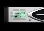
(TEMPORARY) INSTALLATION/USER MANUAL
GD1
DISPLAY, CONTROL AND BATTERY MONITORING UNIT
MASTERVOLT
Snijdersbergweg 93,
1105 AN Amsterdam
The Netherlands
Tel.: +31-20-3422100
Fax.: +31-20-6971006
www.mastervolt.com
This guide is for use with system software version 15.
1.
INTRODUCTION ................................................................................... 3
2.
INSTALLATION ..................................................................................... 4
3.
SETUP .............................................................................................. 6
3.1 SYSTEM SETUP PAGE 1 ......................................................................... 6
3.2 SYSTEM SETUP PAGE 2 ......................................................................... 6
3.3 SYSTEM SETUP PAGE 3 ......................................................................... 7
3.4 SYSTEM SETUP PAGE 4 ......................................................................... 8
4.
HANDLING AND OPERATION ................................................................... 11
4.1 OVERVIEW OF USER INTERFACE ............................................................. 11
4.1.1 SCREEN 0 - Main screen ................................................................ 11
4.1.2 SCREEN 1 - Battery monitoring screen ............................................... 13
4.1.3 SCREEN 2 - Controller and motor monitoring screen .............................. 14
4.2 OPERATING GD1............................................................................... 15
4.2.1 Notification system ..................................................................... 15
4.2.2 Automatic scrolling to Screen 0 ....................................................... 16
4.2.3 Charging/Discharging Detection ...................................................... 16
5.
ERROR MESSAGES AND ERROR CODES ....................................................... 18
6.
TECHNICAL SPECIFICATIONS................................................................... 20
1.
INTRODUCTION
GD1 is a display, control and battery monitoring unit. It is intended to be used in electrically
propelled vehicles as an add-on to one of Mastervolt's AC motor controllers.
It serves as a graphical user interface between the user and the controller. User can set the
speed of the motor and see current speed as well as a range of other quantities such as
battery voltage, battery current, motor current, remaining time of driving at current
consumption etc. At the same time GD1 unit observes the state of charge of the battery,
that is, how much charge there is left, how much was charged and how much discharged. It
detects when battery is being charged, sounds alarm when battery is low etc. GD1 is linked
to one of Mastervolt's motor controllers over CAN bus. In addition of sending reference for
motor RPM or torque to controlled it also receives various data from it. This data is then
displayed on screen. GD1 also has extensive built-in safety systems that informs the user of
an error in the form of on screen message. It also improves energy conservation on board
with configurable sleep mode.
Figure 1: Integration of GD1 unit in 24V - 48V systems (SAC4)
2.
INSTALLATION
GD1 has two Molex connectors on the backside:
Figure 3: Backside of GD1 unit
Connectors have the following pinout:
12-PIN MOLEX
1 - Shunt +
2 - Shunt 3 - Motor temperature sensor
4 - ECONOMY MODE switch
5 - GND
6 - Supply voltage
7 - Do not connect
8 - Throttle
9 - GND
10 - Do not connect
11 - START switch
12 - External relay
4-PIN MOLEX
1
2
3
4
- CAN bus A
- GND
- CAN bus B
-
It is recommended you use original set of cables supplied by the company.
Notes:
–
Shunt cables must be shielded twisted pair. If you do not use shunt resistor, please
short SHUNT+ and SHUNT- and connect them both to GND.
–
For details on the selection and configuration of motor temperature sensor please see
SAC4 / SAC40 user's guide
–
Economy mode switch has internal pull-up and connects to ground when active. The
purpose of this switch is additional limitation of RPM / torque. It is useful for example
as additional safeguard when navigating your boat in a port.
It is recommended that you use company supplied throttle, as shown in the picture below:
Figure 4: Example of speed throttle as supplied by the
company
If you want to use your own throttle, connect slider of throttle potentiometer to Molex 12 pin 8. Other side of potentiometer must be connected to GND via 50E resistor:
Polarity of potentiometer does not matter. You can configure in Setup which direction is
forward / backward.
- START switch wakes the unit from standby when supply voltage is delivered to this pin. Has
internal pull-down.
- External relay connection controls DC link charging at SAC40. See Figure 2.
- CAN bus cables must be shielded twisted pair
3.
SETUP
Before GD1 unit can be used, it must be properly configured. To enter setup, connect GD1
to battery and hold OK while you restart GD1 with START switch.
You will enter first page of setup, which requires no PIN code to change parameters.
Without PIN code you can still view parameters on following pages. However, you cannot
change them. You can navigate through setup with all three buttons. Press UP or DOWN to
select next parameter. When you reach last parameter on page, press DOWN again to go to
next page. Or if you reached first parameter on page, press UP to go to previous screen.
To edit a parameter, press OK. If you have permission to change it then there will appear a
'>' sign in front of the value. You can now change the value using UP / DOWN keys. If you
hold the key for a longer time, you will notice that values change faster and faster - this will
help you select desired value faster. When you entered the desired value just press enter to
store the value and proceed with other parameters.
When entering a PIN code, press OK to enter edit mode. Then select first digit with UP /
DOWN and press OK to proceed to next digit. Repeat until all the digits are entered. If you
entered valid PIN code, you will be granted permission to edit. If not, you will have to wait
30 seconds to try again. Once a valid PIN is entered, the field will be masked with
checkmarks.
3.1 SYSTEM SETUP PAGE 1
Language
Select desired language. Currently, English and
German languages are supported
Contrast
Select contrast of LCD module.
Backlight
Select this option if you want to turn on backlight
for LCD module.
Speaker
Turn speaker on or off.
Serial number
Read-only. Shows serial number of GD1 unit.
Firmware
version
Read-only. Shown software version in your GD1
unit.
3.2 SYSTEM SETUP PAGE 2
Enter
write- Enter PIN code if you want to edit parameters. If
you do not enter PIN code, you can still view the
access PIN
parameters, but you cannot change them (except
on Page 1)
Nominal Ah
Total capacity of your battery pack, meassured
for 20h discharge rate. If your batteries are
connected in series, enter the capacity of a single
battery. If connected in parallel, enter capacity
of a single battery times number of batteries.
Range of this paramter is 1 - 999Ah.
Peukert
Peukert's coefficient determines how rate of
discharge affects remaining charge in the battery.
For example: if you discharge your battery in
short time with higher current, it will deliver less
charge than if you discharge it over twice the
period with only half the current. The lower the
Peukert's coefficient, the better you battery is at
handling large currents. Typical value is 1.25.
Shunt1)
Current in amperes flowing through shunt resistor
that produces voltage drop of 50mV. This current
is also about the maximum battery current
allowed. If it is strongly exceeded, it will saturate
the measuring electronics and therefor affect
GD1's ability to asess remainign battery charge.
Please keep this in mind when selecting your
shunt resistor. Range of this parameter is 20 600A at 50mV.
Charging ends at Voltage at which GD1 detects end of charging and
voltage2)
restores charging counter to 100%. You can enter
values between 10.0V and 340.0V.
Notes:
1)
If your nominal shunt voltage is other than 50mV, please recalculate it to 50mV.
For example:
Your shunt states 360A / 60mV. For the same resistance the equivalent would be
300A / 50mV, so for such a shunt you should enter 300A/50mV.
2)
Charging ends at voltage parameter works in combination with [and current <]
parameter (see SYSTEM SETUP PAGE 3)
3.3 SYSTEM SETUP PAGE 3
and current <1)
Current at which GD1 detects end of charging
and restores charging counter to 100%. You can
enter values between 0.1A and 9.9A.
Charging thresh.
Charging threshold current is current at which
GD1 considers that battery is being charged. You
can enter values between 0.1A and 9.9A.
Disc. thresh.
Discharging threshold current is current at which
GD1 considers that battery is being discharged.
You can enter values between 0.1A and 9.9A.
Ubatt at 50%
Battery voltage at which the remaining charge in
your battery is at 50%. GD1 has a fixed
programmed slope of relation Ubatt vs. State-ofcharge. From it it can calculate voltage at 100%
and at 0%. Range of this parameter is 10 - 300V.
Low-batt alarm
Remaining percent of charge in the battery when
low-battery alarm should go off. Alarm is
presented in a form of message on the screen. To
turn it off, set this option to '--'.
Sleep
(Min/Sec)
after After this time the unit will go into sleep mode if
throttle is in neutral position and there is no
action from the user. LCD display and controller
will be turned off and you have to restart the
system with START button to wake it up.
However, battery voltage and current will still be
measured. To turn this timer off, set time to
'--:--'.
Note:
1)
This condition works in combination with [Charging end at voltage] parameter.
3.4 SYSTEM SETUP PAGE 4
On this page you can calibrate your throttle. You can set where is the neutral position of the
throttle (motor is not running) and set how far you must move the throttle to reach full RPM
of the motor. Note that values on this page can only be changed by moving the throttle
itself. They cannot be changed with UP / DOWN keys. Position of your throttle is measured
in small steps, called quants. Throttle can occupy any of up to 1024 positions or quants.
To ensure consistency of selected position, this calibration can only be done in sequence. To
start the sequence, press OK, else press UP or DOWN to move to another page:
Neutral
First you must select neutral position. In this
position motor will be turned off. When set,
press OK to continue with next position.
Max. forward
Position where motor should have full RPM or
torque in forward direction. Note that you can
select whatever physical direction of throttle
you desire. This means that you do not have to
worry if throttle is mounted on right or left side
of cockpit. GD1 will recognize this automatically.
When set, press OK to continue with next
position.
Max. backward
Position where motor should have full RPM or
torque in backward direction. You will only be
allowed to move the throttle in opposite
direction of forward range, which makes perfect
sense. You cannot overlap forward and backward
range. When set, press OK to finish calibration.
For more technical details please read notes below and take a look at Figure 7.
Notes:
–
Around neutral position there is also a small area that is called 'backlash'. While
throttle is positioned inside this range it is still considered as in neutral position. The
motor will still be turned off. Purpose of this area is to compensate for mechanical
construction of throttle and also to allow comfortable selection of neutral position
when driving. Value of backlash is by default 1/8 of range forward or backward,
whichever is smaller, and is set after throttle calibration sequence is finished. Backlash
can also be manually corrected on next page of setup and can be set up to 1/4 of
described range.
–
Neutral position has a limited range, as can be seen in Figure 7.
–
For security reasons, however, you must move throttle for at least 16 quants from
neutral position to produce enough forward range.
–
A part of range is reserved to detect when throttle is disconnected.
–
Note that with throttle you can command either RPM of the motor or the torque on
shaft. This option can be selected elsewhere in the setup.
Figure 7: Relation of throttle position and A/D quants. Effectively, bottom
figure displays relation of throttle position vs. motor speed or torque.
4.
HANDLING AND OPERATION
If you have correctly installed the GD1 module and have also configured all the parameters
then you can start using GD1 unit.
When you turn START switch on, you will see logo on the screen for a few seconds. If there
are no errors then you will see the main screen (Screen 0). There are a total of 3 screens
and you can scroll between them with UP / DOWN keys.
Description of elements on each screen is provided below.
4.1 OVERVIEW OF USER INTERFACE
UP
DOWN
OK
DISPLAY AREA
4.1.1 SCREEN 0 - Main screen
1 Indicator of screen number
2 Estimated remaining time of driving
3 Battery current
4 Remaining battery charge (State-of-charge)
5 Status line
7 Speed value (RPM)
8 Speed indicator (RPM)
1
Indicator of screen number
2
Estimated remaining time of driving at this current consumption. After this time
battery will probably be empty. This value is masked with '--:--' if
●
motor has less than 50 RPM
●
no current flows from the battery or current flows into battery
●
remaining time is greater than 10 hours
3
Battery current. Current is positive when it is flowing from battery to load.
4
Remaining battery charge (State-of-charge)
5
Status line is showing:
●
Motor direction. When arrow symbol in status line is pointing up then the motor
is spinning forward. When it is pointing down then the motor is spinning
backward.
●
Presence of ECONOMY MODE. When you turn ECONOMY MODE switch on, status
line will show ECONOMY. When you are driving in economy mode you have
additional limitation of RPM. This lower limit is configured in setup and is the
same for forward and backward speed (see setup section of this document).
7
Estimated value of RPM (speed). When arrow symbol in status line is pointing up then
the motor is spinning forward. When it is pointing down then the motor is spinning
backward.
8
Speed (RPM) indicator. Gives you visual feedback of your current speed.
4.1.2 SCREEN 1 - Battery monitoring screen
1 Indicator of screen number
2 Charge charged
3 Amount of remaining charge
4 Battery current
5 Battery voltage
6 Charge used
1
Indicator of screen number.
2
Charge charged. Displays amount of charge that was charged into the battery and is
obtained using the simple integral of current. It can only be increased or reset to zero.
Ah charged gets reset at the beginning of charging. and Ah used at beginning of
discharging. By partial charges, when battery was not fully charged (see chapter
Operating GD1), this counter only get incremented up to max. value.
3
Amount of remaining charge expressed in percent. This value is also referred to as a
State-of-charge (SOC) and is calculated using Peukert's equation. Please refer to the
note below for more information.
4
Battery current. Current is positive when it is flowing from battery to load.
5
Battery voltage.
6
Charge used. Displays amount of charge that was extracted from the battery. And is
obtained using the simple integral of current. It can only be increased or reset to
zero. Ah used gets reset at the beginning of discharging. By partial charges, when
battery was not fully charged (see chapter Operating GD1), this counter only get
incremented up to max. value.
Note: SOC is calculated using Peukert's equation, which provides a more realistic
calculation of remaining charge:
t=
Qn
⎛
⎜
⎜ I
⎜ Qn
⎜
⎝ tn
⎞
⎟
⎟
⎟
⎟
⎠
n
*
tn t
Qn
discharge time
I
discharge current
tn
nominal discharge time, usually taken as 20 hours (Qn/20 or
more commonly named C/20).
Qn
nominal battery charge battery capacity (C). This is the capacity
stated on your battery. If your battery is rated for 20 hours and
you discharge it with just the right current so that it will be
empty after 20 hours, you will be able to extract nominal charge
or the stated capacity.
n
Peukert coefficient. It determines how rate of discharge affects
remaining charge in the battery. The more it approaches 1, the
more is your battery ideal and provides the same charge at high
and low discharge currents. It can be configured in Setup. Typical
value is 1.25.
For example:
Your battery has stated capacity of 100Ah for discharge rate of 20 hours. This
means that if you discharge it with 5A (C/20), you will be able to extract 100Ah.
This will happen in 20 hours.
This, however, does not mean that discharging it with 20A will provide you the same
100Ah in 5 hours time. In reality, you will be able to extract much less. How much
can be determined with above equation.
Peukert equation holds true only for discharging and not also for charging.
From these 3 values you can determine physical charge that was charged to or
extracted from the battery. And you can also see approximately how full your
battery still is.
4.1.3 SCREEN 2 - Controller and motor monitoring screen
1 Indicator of screen number
2 Throttle position
3 Controller temperature
4 Input power
5 Motor RPM direction and RPM value
6 Motor current
7 Motor temperature
1
Indicator of screen number.
2
Throttle position. Upper number represents position in quants, lower number
represents position as percentage range forward (positive sign) or backward (negative
sign).
3
Controller temperature.
4
Input power. This is a product of battery voltage and current through shunt resistor.
5
Motor RPM direction and RPM value. If circular arrow is pointing up then the motor is
turning in forward direction, if down then in backward direction.
6
Motor current.
7
Motor temperature
4.2 OPERATING GD1
Now that you are familiar with user interface and displayed data, you must also know how
to handle other functions. You have already learned that START switch wakes the unit from
sleep or puts it into sleep. If throttle is in neutral position long enough and there was no
action from user then GD1 will go into sleep mode. This time is configured in Setup. In sleep
mode LCD display is turned off, but GD1 still remains active and monitors battery voltage
and current. Before it goes into sleep mode, it also disables the controlled and so saves
energy.
You have also learned that ECONOMY MODE switch limits RPM to allow easier navigation in
ports.
4.2.1 Notification system
Notification system informs you if there is something wrong with any part of the system.
When such an error occurs there will appear a message on the screen, titled "NEW
MESSAGE". When error is related to functionality of GD1 unit then error number will be
displayed as well as message itself. For example "ERR 001: Move throttle to neutral
position". When error is related to controller then controller error will be displayed
followed by message. For example " CONTROLLER ERR 004: Voltage low at start".
When you have read new message, confirm this with OK button. If there are any other
messages then they will also be displayed and you will have to press OK button to confirm
them, until you will finally return to one of three screens. If you wish to see which errors
are still present, press OK on any of the screens. You will now be able to browse message
and the screen will be titled "MESSAGE LIST". Press UP / DOWN to scroll between messages.
If there are no messages in the list then you will read "NO MESSAGES". Press OK to exit
browsing the messages and to return to main screen. Note that when cause of error is
removed then the message will automatically be deleted from the list.
There are various error messages for different problems - from problems with CAN bus,
disconnection of throttle, voltage problems etc. For list of all messages please see the
chapter "LIST OF MESSAGES AND ERROR CODES".
If CAN bus gets disconnected then all the values that depend on successful CAN
communication with controller will be masked with '-' signs. For example - on main screen
(Screen 0) you will see '----' where RPM value should be displayed.
4.2.2 Automatic scrolling to Screen 0
If you are viewing Screen 1 or Screen 2 without pressing any buttons for more than 30
seconds then you will be automatically scrolled to Screen 0. That is the main screen and
data presented there is most important and of most interest. Exception to this is charging
mode - when battery is being charged then charging progress is most interesting and there is
no automatic scrolling to Screen 0.
Before you turn the unit on with START switch you must make sure that throttle is in neutral
position. If not then the unit will inform you of that with an error message. This function
makes sure that the boat does not start moving if you forgot to move throttle to neutral
position and just turned START switch on.
Similar thing happens if CAN bus gets disconnected. You will be notified of this problem and
after correcting the error, you will be prompted to move throttle to neutral position. Again,
this ensures safe ride.
Note:
When GD1 unit is connected to battery for the first time, the battery voltage is
measured. State-of-charge (SOC, percentage of remaining charge, displayed on
Screen 1) is then estimated according to battery voltage. This estimation also
depends on parameter 'Ubat at 50%' (see Setup chapter for details). Therefore, if
possible, try to connect GD1 to battery only after battery has rested for a couple of
hours without any load. Otherwise, SOC value will be correct only after first full
charge.
4.2.3 Charging/Discharging Detection
When conditions for charging are met then displays detects charging. If START switch is on
(normal operation) then user is notified with two beeps and LCD backlight turns on for 10
seconds (if these options are turned on in Setup). If START switch is turned off (sleep mode)
then the same happens, plus user is presented with Battery monitoring screen (Screen 1).
There the arrow that symbolizes charged Ah start blinking.
It keeps blinking until charging takes place. After that GD1 returns to sleep mode.
Because GD1 must detect various types of charging, regardless of whether battery is full or
empty or if different types of chargers are used, there exists a set of rules that describes
charging.
Battery is considered to be in charging mode if:
–
Negative (charging) current flows for more than 6 seconds. This way possible short bursts of
charging current from induction of motor are ignored. This current must be equal to or
greater than current charging threshold set under Setup - Page 3, parameter "2 - Charging
thresh"
–
Or for more than 6 seconds battery voltage is greater than voltage set in Setup - Page 2,
parameter "5 - Charging ends at voltage". This ensures that charging will still be detected in
case that baterry is already full and there flows almost no current.
–
If controller is turned off and there flows negative (charging current), 6 seconds margin is
skipped and battery is immediately considered as being charged.
Battery is considered to be charged to full when:
–
For more than 10 minutes flows current smaller than the value set in Setup - Page 3,
parameter "1 - 'and current <"
–
And for more than 10 seconds battery voltage is higher than voltage set in Setup - Page 2,
parameter "5 - Charging ends at voltage"
When battery is charged to full then State-of-charge (SOC) counter (percent of remaining
capacity in the battery) is set to 100% (see description of Screen 1 - Battery monitoring
screen).
Battery is considered to be in discharging mode when:
–
Positive (discharging) current flows for more than 6 seconds. This way possible short bursts of
discharging are ignored. This current must be equal to or greater than current discharging
threshold set under Setup - Page 3, parameter "3 - Disc. Thresh."
Currents that do not satisfy above condition are ignored and do not influence charge
counters displayed on Screen 1 - Battery monitoring screen.
5.
ERROR MESSAGES AND ERROR CODES
List of all messages and error codes is provided below:
ERR 001: Move throttle to neutral position
ERR 002: Throttle error/disconnected
ERR 003: CAN bus timeout
ERR 004: Battery low
ERR 005: Motor temperature high. Reducing power.
ERR 006: High Voltage PCB timeout/no link
CONTROLLER ERR 001: Over current
CONTROLLER ERR 002: Over voltage
CONTROLLER ERR 003: Under voltage
CONTROLLER ERR 004: Voltage low at start
CONTROLLER ERR 005: Potentiometer error during operation
CONTROLLER ERR 006: Potentiometer not zero at start
CONTROLLER ERR 007: Controller over-temperature
CONTROLLER ERR 008: Controller under-temperature
CONTROLLER ERR 009: Controller temperature sensor error
CONTROLLER ERR 010: Current offset error
CONTROLLER ERR 011: DC link charging error
CONTROLLER ERR 012: Relay error
CONTROLLER ERR 013: PDPINTA (shortcut or mosfet/driver error)
CONTROLLER ERR 014: Bad user parameter CRC
CONTROLLER ERR 015: Bad system parameter CRC
CONTROLLER ERR 016: Bad flash CRC
CONTROLLER ERR 017: Wrong parameter version
CONTROLLER ERR 018: Invalid motor type
CONTROLLER ERR 019: Autotuning error
CONTROLLER ERR 020: Boost error
CONTROLLER ERR 021: Motor over-temperature
CONTROLLER ERR 022: Motor temperature sensor failure
CONTROLLER ERR 023: Internal error
6.
TECHNICAL SPECIFICATIONS
GD1 unit
Supply voltage
15 - 60 VDC
Supply current
(in normal operation)
Current measurement range
Display
Vcc / Icc / Icc with backlight / Icc in sleep mode
24V / 25mA / 153mA / 17mA
36V / 48mA / 119mA / 17mA
48V / 53mA / 120mA / 19mA
60V / 55mA / 121mA / 20mA
+- 20A to +-600A, configurable in Setup
LCD monochrome 128 x 64
Temperature range
Relative humidity
Dimensions
Weight
-25°C to +60°C
5 - 95 % (vapor)
138 x 90 x 31mm [L x W x H]
250g
Warning - this device is susceptible to damage from electrostatic discharge.