1
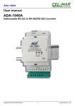
ADA-I911W
User manual
ADA-I911W
USB to 1-WIRE converter
Copyright © 2001-2014 CEL-MAR sp.j.
1
io_ada-i911w_v en. 1.00
ADA-I911W
Contents
1. GENERAL INFORMATION...................................................................................................................................................................... 3
1.1. WARRANTED INFORMATION ...................................................................................................................................................... 3
1.2. GENERAL CONDITIONS FOR SAFE USE.................................................................................................................................... 3
1.3. CE LABEL....................................................................................................................................................................................... 3
1.4. ENVIRONMENTAL PRESERVATION............................................................................................................................................ 3
1.5. SERVICE AND MAINTENANCE..................................................................................................................................................... 3
2. PRODUCT INFORMATION..................................................................................................................................................................... 3
2.1. PROPERTIES................................................................................................................................................................................. 3
2.2. DESCRIPTION................................................................................................................................................................................ 4
2.3. APPLICATION................................................................................................................................................................................ 4
2.4. EPROM MEMORY PROGRAMMING............................................................................................................................................. 4
2.5. 1-WIRE CIRCUITS COMMUNICATION ........................................................................................................................................ 4
2.6. COMMUNICATION VIA VIRTUAL COM PORT.............................................................................................................................. 4
2.7. ISOLATION..................................................................................................................................................................................... 5
3. CONFIGURATION .................................................................................................................................................................................. 5
4. INSTALLATION....................................................................................................................................................................................... 5
4.1. CONNECTION TO USB PORT OF PC........................................................................................................................................... 5
4.2. 1-WIRE SENSORS CONNECTION................................................................................................................................................ 5
4.3. POWER SUPPLY .......................................................................................................................................................................... 6
5. DRIVERS INSTALLATION IN SYSTEM WINDOWS .............................................................................................................................. 6
5.1. EXAMPLE DRIVER INSTALLATION IN WINDOWS 7 SYSTEM...................................................................................................6
6. DRIVER UNINSTALLATION.................................................................................................................................................................. 12
6.1. DRIVER UNINSTALLATION IN WINDOWS 98/ME SYSTEMS...................................................................................................12
6.2. DRIVER UNINSTALLATION IN WINDOWS 2000/XP/2003/VISTA/7/2008 SYSTEMS...............................................................13
6.2.1. EXAMPLE DRIVER UNINSTALLATION IN WINDOWS 7 SYSTEMS.................................................................................13
6.3. EMERGENCY DRIVER UNINSTALLATION................................................................................................................................. 14
6.3.1. EMERGENCY DRIVER UNINSTALLATION IN WINDOWS 98/ME/2000...........................................................................14
6.3.2. EMERGENCY DRIVER UNINSTALLATION IN WINDOWS XP/2003/Vista/7/2008...........................................................14
7. USING................................................................................................................................................................................................... 14
7.1. SELECTION OF COM PORT LARGER THEN COM9.................................................................................................................14
8. 1-WIRE INTERFACE – PIN DESCRIPTION ........................................................................................................................................ 14
9. VERSIONS............................................................................................................................................................................................ 14
10. SPECIFICATION................................................................................................................................................................................. 15
2
ADA-I911W
1. GENERAL INFORMATION
Thank you for your purchase of CEL-MAR Company product. This product has been completely tested and is covered by a lifetime
warranty on parts and operation.
If any questions or problems arise during installation or use of this product, please do not hesitate to contact Technical Support at +48
41 362-12-46 or e-mail [email protected].
1.1. WARRANTED INFORMATION
CEL-MAR Company gives the indefinite guarantee on the ADA-I911W converter. The warranty does not cover damage caused from
improper use, materials consumption or any unauthorized changes. If the product does not function accordance with the instructions
will be repaired. All warranty and no warranty repairs must be returned with paid transport and insuring to the CEL-MAR Company.
CEL-MAR Company under no circumstances won't be responsible for ensuing damage from improper using the product or as a result
of random causes: the lightning discharge, the flood, the fire and the like.
CEL-MAR Company is not be held responsible for damages and loss including: loss of profits, loss of data, pecuniary losses ensuing
from using or the impossibility of using this product.
In specific cases CEL-MAR Company discontinue all warranties and in particular do not follow the user manual and do not accept
terms of warranty by the user.
1.2. GENERAL CONDITIONS FOR SAFE USE
The device should be installed in a safe and stable places (eg, electroinstallation cabinet), the powering cable should be arranged so
as not to be exposed to trampling, attaching, or pulling out of the circuit.
Do not put device on the wet surface.
Do not connect devices for nondescript powering sources,
Do not damage or crush powering wires.
Do not make connection with wet hands.
Do not adapt, open or make holes in casings of the device!
Do not immerse device in water or no other liquid.
Do not put the fire opened on device sources: candles, an oil lamps and the like.
Complete disable from the supply network is only after disconnecting the power supply circuit voltage.
Do not carry out the assembly or disassembly of the device if it is enabled. This may result to short circuit and damage the device.
1.3. CE LABEL
CE symbol on organizing the company CEL-MAR a conformity of the device to the directive of the electromagnetic EMC
2004/108/WE compatibility means (Electromagnetic Compatibility Directive). The declaration of the agreement is
accessible through the contact with the technical service at the address e-mail: [email protected] or on the phone at the
+48 41 362-12-46.
1.4. ENVIRONMENTAL PRESERVATION
This sign on the device inform about putting expended device with other waste materials. Device should send to the
recycling. (In accordance with the act about the Electronic Appliance Expended from day 29 of July 2005)
1.5. SERVICE AND MAINTENANCE
The ADA-I911W converter does not require the servicing and maintenance.
Technical support is available at number +48 41 362-12-46 in 8.00-16.00, from Monday to Friday or e-mail [email protected].
2. PRODUCT INFORMATION
The converter is delivered with User Manual, USB Aw-Bw cable and drivers on CD-R.
2.1. PROPERTIES
●
●
●
●
●
●
●
●
●
●
●
●
●
USB to 1-WIRE conversion,
Signals: RX,TX,
Operating possibility on MicroLAN bus,
Programming possibility of EPROM memory on 1-WIRE bus (version 2-X),
Baud rate on 1-WIRE bus: - standard up to 16,3 kbps, – overdrive up to 142 kbps,
Baud rate virtual COM port (on USB): 9600bps (standard), 19200bps, 57600bps, 115200bps supported by the DS9097U adapter,
Powering from USB port,
1 kV= or 3kV= (option) galvanic isolation between USB and 1-WIRE interfaces,
~3kV= optoisolation between USB and 1-WIRE interfaces on signal line,
USB interface connection via USB socked B-type,
1-WIRE bus connection via screw terminal block,
ABS material for casing,
Casing dimensions (L x H x D) 65mm x 50mm x 27mm,
3
ADA-I911W
2.2. DESCRIPTION
The ADA-I911W USB to 1-WIRE converter allows connection of several 1-WIRE's interface systems such as: temperature
measurement systems, real time clocks, EPROM memory, A/C transducers etc., to common 1-WIRE bus. The transition from 1-WIRE
interface to USB interface in ADA-I911W provides controller 1-Wire bus and the USB controller. In this way, the user does not need to
delve into the quite complicated protocol 1-WIRE. The converter allows monitoring and/or controlling of 1-WIRE circuits via USB
interface of computer PC-class, equipped with suitable software. CEL-MAR company provides an example of software for the
visualization of temperature measurement called Lämpömittari taken by Timo Sara-aho. The software supports circuits for measuring
the temperature eg. DS18S20. In the configuration settings of Lämpömittari software, in section MicroLAN should be used the
DS9097U adapter.
ADA-I911W is equipped with a female USB socket B-type for connection of USB interface and the screw terminal block for twisted-pair
connections of 1-WIRE interface. The converter is powered from USB port. Together with the converter we supply drivers for Windows
98, ME, NT, 2000, XP, 2003, Vista, 7, 2008. Installing this software on Operating System it add the additional COM port about the next
free number, witch can be used as standard COM port. It is virtual COM port therefore some software use DOS can work improperly.
2.3. APPLICATION
ADA-I911W converter can be use in the all types of local systems, based on MicroLAN networks such as: access control, control the
operation of air conditioning and heating, a remote control and monitoring of alarm systems, fire extinguishers, etc.
One of the fastest growing markets today is the market of alarm systems, in which MicroLAN is used for connection the sensors with
alarm control panel, where instead of few or several wires can only use 3. MicroLAN in such use prevents the possibility of "defraud"
alarm system by shorting or cutting the line and at the same time provides ease of automatic configuration and reconfiguration of the
alarm system during operation. Much easier than the standard versions, is also keeping test procedures that help eliminate faulty
system components.
2.4. EPROM MEMORY PROGRAMMING
The version 2-x of ADA-I911W converter allows to programming the EPROM memory. This is done with the switch MODE side of the
housing, in position “PROG”, connecting programmable circuit to the bus and making the programming. If there are circuits to the bus
on which do not require programming, the switch should be set in position “NORM”.
2.5. 1-WIRE CIRCUITS COMMUNICATION
For communication with 1-WIRE circuits can be used the software as follow:
a/ OneWire Viewer available here http://www.maximintegrated.com/en/products/ibutton/software/1wire/OneWireViewer.cfm ,
b/ LogTemp available here http://www.mrsoft.fi/ohj01en.htm ,
c/ Thermometer (Lampomittari) available here http://www.elektroniikka.org/thermometer/?page=download ,
d/ DigiTemp available here https://www.digitemp.com/index.shtml ,
e/ or other, cooperate with DS9097U adapter.
2.6. COMMUNICATION VIA VIRTUAL COM PORT
The communication between ADA-I911W converter and the application is via the virtual COM port, with baud rate 9600bps (the baud
rate set in ADA-I911W after powering) or others, setted by the software of master device (eg. PC) ie.: 19200 bp/s, 57600 bp/s, 115200
bp/s.
66mm
VDD
NC
Rx
ADA-I911W
USB to 1-WIRE
ISOLATED CONVERTER
MODE
PROG
NORM
75mm
Fig. 1. ADA-I911W view
4
47mm
1-W
(1-WIRE)
GND
Tx
USB
PWR
NC
ADA-I911W
2.7. ISOLATION
ADA-I911W converter has 1kV= or 3kV galvanic isolation, depending on the version of device, described in pt. VERSIONS.
ISOLATION
USB
1-WIRE
Fig. 2. Isolation diagram
3. CONFIGURATION
ADA-I911W converter can be set for operating in normal mode or programming mode by the use of MODE switch (fig.1). Description
of the switch modes is shown in the table below.
MODE switch
Function
NORM
Operating in normal mode, allows to read data from the 1-WIRE interface circuits eg. DS18B20
PROG
Operating in programming mode of EPROM memory with 1-WIRE interface
4. INSTALLATION
This chapter will show how to connect ADA-I911W to 1-WIRE and USB interfaces.
To reduce disturbance from environment on 1-WIRE bus, it is recommended to:
- use multipair type shielded cables, which shield can be connected to the earthing on one end of the cable,
- lay signal cables at a distance of not less than 25 cm away from power cables,,
4.1. CONNECTION TO USB PORT OF PC
ADA-I911W converter is connected to USB of PC by the use USB Aw-Bw cable, supplied with the converter.
4.2. 1-WIRE SENSORS CONNECTION
For connection of 1-WIRE bus to ADA-I911W converter, should have flat screwdriver for connection of wires to terminal block. The
connections of 1-WIRE sensors to ADA-I911W are shown below.
ADA-I911W
PC
USB
1-WIRE
connector connector
USB
A
USB
B
1-WIRE (3W) Network
GND
1-W
VDD
GND
DQ
VDD
GND
DQ
VDD
GND
DQ
VDD
Sensor
DS18B20
Sensor
DS18B20
Sensor
DS18B20
Fig 4. Sensors connection to ADA-I911W by 3-wire 1-WIRE bus.
5
ADA-I911W
ADA-I911W
PC
USB
1-WIRE
connector connector
USB
A
1-WIRE (2W) Network
GND
1-W
VDD
USB
B
GND
DQ
VDD
GND
DQ
VDD
GND
DQ
VDD
Sensor
DS18B20
Sensor
DS18B20
Sensor
DS18B20
Fig 5. Sensors connection to ADA-I911W by 2-wire 1-WIRE bus.
4.3. POWER SUPPLY
The converter is powered from USB port of PC. After connection to USB port, will start driver installation and after that, the green LED
PWR should be lit. If doesn't check:
- the computer is running,
- the connection of converter cable to the computer,
- hibernation mode of computer,
- the correctness of driver installation.
5. DRIVERS INSTALLATION IN SYSTEM WINDOWS
ADA-I911W is delivered with the driver package Installer for Windows systems on CD-ROM.
For installation follow the steps below:
a/ insert the CD-ROM to optical driver of the computer,
b/ the installation wizard will run automatically, if not double click ADAUSBDRV.exe.
c/ follow the steps of installation wizard, will be installed the Drivers and Uninstaller for the Windows systems 98, ME, 2000, XP,
2003, Vista, Win7, 2008, Win8,
d/ connect the convert to USB port of computer and follow the steps of installation wizard.
5.1. EXAMPLE DRIVER INSTALLATION IN WINDOWS 7 SYSTEM
ADA-I911W is delivered with the drivers for Windows system 98/ME/2000/XP/Vista/7/2008 Win8
Driver installation have to be done from the account with Administrator permissions. For the drivers installation in Win7 follow the
steps bellow:
a/ insert the CD-ROM to optical driver of computer,
b/ the installation wizard will run automatically, if not double click ADAUSBDRV.exe form the CD-ROM.
After running the installer, the wizard installation window will appear.
6
ADA-I911W
Press [Next]
Select STANDARD Drivers and press [Next]
7
ADA-I911W
Press [Install]
Press [Next], will be installed Drivers for USB Bus.
8
ADA-I911W
Press [Install this driver software anyway]. Installation of drivers for USB Bus will start.
9
ADA-I911W
Press [Install this driver software anyway]. Installation of drivers for Virtual Port will start.
10
ADA-I911W
Press [Finish]
Press [Finish].
The driver for ADA-I911W have been installed. This can be checked in “Uninstall or change a program“.
11
ADA-I911W
Now connect ADA-I911W to computer port.
After connection will appear the Tool tip with [Your device is ready to use]. To see the details press the Tooltip, and will appear
information window where is shown which COM port was assigned to converter.
After this installation, RS232 port of ADA-I911W converter is available in the system as normal COM port. Should remember about
specified baud rate for communication
If during installation was selected driver for Standard baud rates, it is possible to use:
9600 bps (standard), 19200 bps, 57600 bps, 115200 bps supported by the DS9097U adapter. Selecting other baud rates will result in
no reading of 1-WIRE circuits.
6. DRIVER UNINSTALLATION
6.1. DRIVER UNINSTALLATION IN WINDOWS 98/ME SYSTEMS
In this operating system driver uninstallation have to be done according follow steps:
a/ disconnect converter from computer,
b/ select menu Start > Setting > Control Panel > Add > Remove Programs,
c/ select from the list “ADA USB Serial Converter Driver” and press [Change / Remove],
e/ reboot the computer.
12
ADA-I911W
6.2. DRIVER UNINSTALLATION IN WINDOWS 2000/XP/2003/VISTA/7/2008 SYSTEMS
Drivers uninstallation in Windows2000/XP/2003/Vista/7/2008, have to be done according follow steps:
a/ disconnect converter from computer,
b/ login as the Administrator,
c/ select menu Start > Setting > Control Panel > Add > Remove Programs,
d/ select from the list Windows Driver Package – CEL-MAR ADA – Virtual USB Serial Port,
e/ press [Change / Remove], Virtual USB Serial Port driver will be uninstalled,
f/ select from the list Windows Driver Package – CEL-MAR ADA – USB Serial Converter,
g/ press [Change / Remove], driver converter of USB Bus will be uninstalled,
h/ after uninstallation reboot the computer.
6.2.1. EXAMPLE DRIVER UNINSTALLATION IN WINDOWS 7 SYSTEMS
Driver uninstallation in Windows 7 system, have to be done according follow steps:
a/ disconnect converter from computer,
b/ login the Administrator account ,
c/ select menu Start > Control Panel > Programs > Uninstall,
d/ select from Windows Driver Package – CEL-MAR ADA – Virtual USB Serial Port,
e/ press [Uninstall/Change], Virtual USB Serial Port driver will be uninstalled
f/ select from the list Windows Driver Package – CEL-MAR ADA – USB Serial Converter
g/ press [Uninstall/Change], driver converter of USB Bus will be uninstalled,
h/ after uninstallation reboot the computer.
13
ADA-I911W
6.3. EMERGENCY DRIVER UNINSTALLATION
If there are problems with correct operation of drivers or converter and or on the computer was installed driver other devices this type,
it is possible to use the special software form delivered CD-ROM to clean the system form files and entries in the system registry. This
can be done after uninstallation descried in point 6.1 and 6.2.
6.3.1. EMERGENCY DRIVER UNINSTALLATION IN WINDOWS 98/ME/2000
Emergency driver uninstallation in Windows 98/ME/2000 system have to be done according follow steps:
a/ disconnect converter from computer,
b/ from CD-ROM delivered with converter, copy to hard disk the folder Windows\Win-98ME_1.09.06\FTClean for Windows 98/ME or
Windows\Win-2000\FTClean for Windows 2000,
c/ from FTClean folder run the application FTClean.exe and follow the Tooltip,
d/ after finishing, reboot the computer.
6.3.2. EMERGENCY DRIVER UNINSTALLATION IN WINDOWS XP/2003/Vista/7/2008
Emergency driver uninstallation in Windows XP/2003/Vista/7/2008 system have to be done according follow steps:
a/ disconnect converter from computer,
b/ login the Administrator account,
c/ from CD-ROM delivered with converter, copy to hard disk the folder Windows\Win-XP-2003-Vista-7-2008_2.06\ CDMUninstaller,
d/ from CDMUninstaller folder run the application uninstall.bat,
e/ after finishing, reboot the computer.
7. USING
After proper connection according to section above the converter can be used. If connection of USB cable was made property green
LED PWR on front panel of converter should lit. If doesn't, check the connection of converter to the computer or computer is ON and
or it isn't in hibernation mode.
During data transmission LEDs should blink and they indicate appropriately:
LED
Description
PWR
Signalling of Powering
RX
Signalling of data receiving through ADA-I911W from 1-WIRE port.
TX
Signalling of data transmitting from ADA-I911W through 1-WIRE port .
7.1. SELECTION OF COM PORT LARGER THEN COM9
If virtual port COM of converter will install in Windows OS as COM10 or larger then in application using this port, should be typed COM
port address as: \\.\COM10.
8. 1-WIRE INTERFACE – PIN DESCRIPTION
Description
Pin
VDD
Voltage + 5V, power the 3-wire 1-WIRE bus
1-W
The data transmission 1-Wire bus corresponds to DQ pin DS18B20 circuit
GND
1-WIRE bus ground
9. VERSIONS
ADA-I911W -
-
Electronics version:
Without possibility of memory
programming from the 1-WIRE interface
1
With possibility of memory programming
from the 1-WIRE interface
2
Order example:
Product symbol: ADA-I911W-2-2
2 - with possibility of memory programming from the 1-WIRE
interface
2 - 1kV= galvanic isolation,
Galvanic isolation:
1kV=
2
3kV= ( option )
3
14
ADA-I911W
10. SPECIFICATION
Parameters
USB
Connector
1-WIRE
B-type female
Line length
Screw terminal block, max. wire Ø2,5mm²
up to 5 m
up to 300 m – for DS1820 sensors
1
Maximum number of connected devices
up to 100 of DS18B20 circuits
Twisted cable 1-pair, 2- pair UTP Cat.5e,
shield inside large interferences STP Cat. 5e.
standard: 0 do 16,3 kbps,
overdrive: 0 do 142 kbps,
Transmission line
USB Aw-Bw cable
Standards
9.6, 19.2, 57.6, 115.2 [kbit/sec]
Maximum baud rate
USB1.1, USB2.0
Transmission type
1-WIRE - half duplex (transmitting and receiving on the same wire)
Optical Signalization
1-WIRE
• PWD – green LED power supply,
• RX – red LED received data via 1-WIRE interface,
• TX – yellow LED transmitted data via 1-WIRE interface.
Nominal work conditions
Power requirements
from USB of Computer
Power
<1W
Galvanic Isolation
1kV DC or 3kV DC – between USB and 1-WIRE interfaces
Optoisolation
~3kV - between signal line USB and 1-WIRE interfaces
0 ÷ +23 ÷ +50°C
Operating temperature
Humidity
5 ÷ 95% - non-condensing
Location during work
Free
Electromagnetic compatibility
Resistance to disruptions according to the standard PN-EN 55024.
Emission of disruptions according to the standard PN-EN 55022.
Safety requiring
According to the PN-EN60950 norm.
Environment
Commercial and light industrial.
Casing
Dimensions (W x D x H)
65mm x 50mm x 27mm
Material
ABS
Degree of casing protection
IP20
< 0,10 kg
Weight
Conditions of storing and transportation
Storage temperature
-20 ÷ +60 °C
5 ÷ 95% - non-condensing
Humidity
15
ADA-I911W
Dear Customer,
Thank you for purchasing CEL-MAR Company products.
We hope that this user manual helped connect and start up the ADA-I911W converter. We also wish to inform you that we are a
manufacturer of the widest selections of data communications products in the world such as: data transmission converters with
interface RS232, RS485, RS422, USB, Current Loop, Fibre-Optic Converters and Ethernet or Wi-Fi.
Please contact us to tell how you like our products and how we can satisfy you present and future expectation.
CEL-MAR sp.j.
Zakład Informatyki i Elektroniki
str. Ściegiennego 219C
25-116 Kielce, POLAND
Tel....................................................: +48 41 362-12-46
Tel/fax..............................................: +48 41 361-07-70
Web.................................................: http://www.cel-mar.pl/en
Office...............................................: [email protected]
Sales department........................... .: [email protected]
Technical information ..................... : [email protected]
16