1
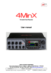
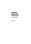
RO6700/RO6700N2K/RO6800AIS User Manual RF Radiation Information RF Radiation Profile Your radio is designed and tested to comply with a number of national and international standards and guidelines (listed below) regarding human exposure to radio frequency electromagnetic energy. This radio complies with the IEEE and ICNIRP exposure limits for occupational/controlled RF exposure environment at operating duty factors of up to 50% transmitting .In terms of measuring RF energy for compliance with the FCC exposure guidelines, your radio radiates measurable RF energy only while it is transmitting (during talking in PTT mode), not when it is receiving (listening) or in standby mode. The device complies with SAR and/or RF field strength limits of RSS-102 requirement RF Radiation Safety In order to ensure user health, experts from relevant industries including science, engineering, medicine and health work with international organizations to develop standards for safe exposure to RF radiation. These standards consist of: United States Federal Communications Commission, Code of Federal Regulations; 47CFR part 2 sub-part J; American National Standards Institute (ANSI)/Institute of Electrical and Electronic Engineers (IEEE) C95. 1-1992; Institute of Electrical and Electronic Engineers (IEEE) C95. 1 – 1999; International Commission on Non-Ionizing Radiation Protection (ICNIRP) 1998; FCC Regulations Federal Communication Commission (FCC) requires that all radio communication products should meet the requirements set forth in the above standards before they can be marketed in the U.S, and the manufacturer sHAIL post a RF label on the product to inform users of operational instructions, so as to enhance their occupational health against exposure to RF energy. Part 15 Compliance This equipment has been tested and found to comply with the limits for a Class B digital device, pursuant to part 15 of the FCC Rules. These limits are designed to provide reasonable protection against harmful interference in a residential installation. This equipment generates uses and can radiate radio frequency energy and, if not installed and used in accordance with the instructions, may cause harmful interference to radio communications. However, there is no guarantee that interference will not occur in a particular installation. If this equipment does cause harmful interference to radio or television reception, which can be determined by turning the equipment off and on, the user is encouraged to try to correct the interference by one or more of the following measures: ● Reorient or relocate the receiving antenna. ● Increase the separation between the equipment and receiver. ● Connect the equipment into an outlet on a circuit different from that to which the receiver is connected. ● Consult the dealer or an experienced radio/TV technician for help. Note: “Changes or modifications to —I— this unit not expressly approved by the party responsible for compliance could void the user’s authority to operate the equipment.” EU Regulatory Conformance As certified by the qualified laboratory, the product is in compliance with the essential requirements and other relevant provisions of the Directive 1999/5/EC. Please note that the above information is applicable to EU countries only. Warning- Limitations On Use This RO6800AIS product contains simple chart, only as an aid to navigation for reference. Only Official Government Charts and Notice to Mariners contain all the current information needed for safe navigation. This products feature cannot be relied on as complete or accurate and may vary depending on location. It’s the captain’s responsibility to use official government charts, notices to mariners, caution, sound judgment and proper navigational skills when operating their boat using this product. —II— Contents 1 .Installation ................................................................................................................................... 1 2. Front Panel/Back Panel/Wiring diagram.................................................................................. 3 3.LCD Display ................................................................................................................................. 7 4. Main Menu Operation on Screen .............................................................................................. 7 DSC Menu................................................................................................................................ 7 MY MMSI ID setup .......................................................................................................... 8 Individual Call/Position Request/Group Call/Test call ................................................ 9 All Ship Call................................................................................................................... 11 Receive Call Log ............................................................................................................ 12 Send Call Log ................................................................................................................ 13 Phone Book .................................................................................................................... 14 DSC Setup ...................................................................................................................... 15 Main Menu ............................................................................................................................ 15 VHF Operation .............................................................................................................. 16 GPS Setup ...................................................................................................................... 18 AIS Setup(Only RO6800AIS)......................................................................................... 19 ATIS Operation ............................................................................................................. 20 DSC Operation .............................................................................................................. 21 System Config ................................................................................................................ 21 Distress Menu & Send the Distress Message ...................................................................... 22 AIS Operation (Only RO6800AIS) ...................................................................................... 23 5.Key Operation ............................................................................................................................ 24 Power on/off & rotate to get up/down function .................................................................. 24 Special Function of DISTRESS key & Real-time DSC ...................................................... 24 VOL/AIS Control .................................................................................................................. 25 TRIW/HAIL (Tri Watch/Hailer).......................................................................................... 25 Squelch/MOB Key................................................................................................................. 25 DW/ FOG (Dual Watch/Foghorn)........................................................................................ 26 MEM Key .............................................................................................................................. 26 Scan Key ................................................................................................................................ 26 Hi/Lo....................................................................................................................................... 26 Up/Down Key......................................................................................................................... 27 LOC/DX ................................................................................................................................. 27 16/9 Key.................................................................................................................................. 27 Select second priority channel.............................................................................................. 27 CALL/MENU ........................................................................................................................ 27 Back Light.............................................................................................................................. 28 CH/*/WX ............................................................................................................................... 28 6.Other Features and Solutions.................................................................................................... 28 Special function keys............................................................................................................. 28 TX Time Out.......................................................................................................................... 29 The Local Time & Date on Screen: ..................................................................................... 29 NMEA 0183 and NMEA 2000 .............................................................................................. 29 Appendix B – Channel List .......................................................................................................... 30 International Marine VHF Channels & Frequencies .................................................. 30 U.S. Marine VHF Channels and Frequencies .............................................................. 32 Notes: .................................................................................................................................... 34 Specification........................................................................................................................... 38 1 .Installation The first installation solution 1.Place and fasten the mounting bracket on the console by 4 screws; 2. Mount the base station onto the bracket; 3. Attach the supplied mounting knobs from two sides of the bracket to fix the base station securely (as shown above). The second installation solution: 1 Slide the fixed mount VHF through the corresponding hole on the instrument panel or anywhere you plan to install this VHF. As the below picture shown —1— 2 Use screwdriver respectively tighten the screws on either side of the small mental bracket (as A screw of the below picture shown), make the small metal bracket fit tightly on the aluminum chassis 3 Similarly, use screwdriver respectively tighten the screws on either side of the small metal bracket (as B screw of the below picture shown), that will firmly against the inside of the instrument panel. —2— 2. Front Panel/Back Panel/Wiring diagram Front Panel CH/*/WX—short press to enter private channel, long press to enter weather channel(only available in US). ⑵Back Light On/Off—short press to back light On/Off. ⑶Call/MENU—short press to enter “DSC Menu”, long press to enter “Main Menu”. ⑷16/9—short press to enter channel 16 or press this button to quit all other modes and back to the priority channel quickly, long press will get second-priority channel 09 or any channel that you’ve set as second-priority channel. ⑸LOC/DX—short press to get conversion between local and distance mode (DX allows normal receive sensitivity; and “LOCAL” eliminates receiver noise, but degrades receiver sensitivity meanwhile “LOCAL” icon display on LCD). ⑹HI/LO—short press to toggle between 25watt and 1 watt output. “HI” or “LO” icon appears on LCD display to indicate setting. ⑺SCAN—short press to enter all scan/all memory scan, long press to enter priority all/memory —3— scan. ⑻MEM—short press to enter memory mode, long press to save/delete memory channel. ⑼DW/FOG—short press to enter Dual Watch Mode, long press to enter “Foghorn Menu”. ⑽SQL/MOB—short press to get SQL setting, long press to get MOB activated. ⑾TRIW/HAIL—short press to enter Tri Watch Mode, long press to enter “HAILER LISTEN MODE” and set volume as you wish. ⑿ VOL/AIS—short press to enter volume set, long press to enter AIS (Automatically Identification System RO6800AIS only). ⒀ Handset connector. ⒁Generally it acts exit function as “Exit” icon show on screen. At initial screen, it also acts UP key function; ⒂ Soft key--short press to get channel up, long press to make channel up much faster. ⒃ Soft key--short press to get channel down, long press to make channel down much faster. ⒄Generally it acts enter function as “Enter” icon show on screen. At INITIAL screen, it also acts Down key function; ⒅DISTRESS—Pull up key cover and press to start Distress Alert Calling if you programmed your radio with an MMSI number. ⒆Power on/off—short press to turn it on, long press to turn it off. Rotate knob to get up/down function when radio is on. —4— Back Panel ⑴ RF antenna ⑵ Power + ⑶ Power ⑷ Hailer ⑸external speaker jack ⑹NMEA 0183/2000 ⑺Test &USB ⑻GND hole Wiring diagram —5— As above show, the “number in picture” correspond to “wiring number” also correspond to “the number in the below table” The details please check the below table Serial Number ⑴ General Description RF antenna connector Function Description connect with antenna ⑵ ﹨ power white black Red white Bare Orange Yellow Black Red Brown Green Bare Brown Yellow Orange Black Red Green Bare ﹨ ﹨ Power supply ⑶ black ⑷ audio connector in red Hailer ⑸ audio connector in white External Speaker Mouse cable A NMEA0183 & NMEA2000 ⑺ Mouse cable B TEST & USB ⑻ GND connection hole ﹨ ﹨ Power+ +13.8V PowerGND HAILER+ HAILERAUDIO+ AUDIOGND 0183_IN+ 0183_IN0183_OUT+ 0183_OUTCANL CANH GND GND NC Speaker Mic USB_RX USB_TX GND red red&black ⑹ Different Color Description —6— 3. LCD Display DSC 25W P-CH SQL:5 VOL:3 INT 16 DISTRESS 12:07:38 02 MAY 2014 Fri CH ▲ CH▼ 4. Main Menu Operation on Screen DSC Menu Short press the CALL/MENU key will be displayed as below on LCD: DSC Menu Individual Call Position Request All Ship Call Group Call Test Call Receive Call Log Send Call Log Phone Book DSC Setup My MMSI ID EXIT ▲ ▼ ENTER Detailed entrance for each catalogue as shown below: —7— MY MMSI ID setup Firstly, long press CALL/MENU key to enter “Main Menu”. Secondly, select “DSC Operation” to enter “MY MMSI ID”. —8— Then you can set up your related MMSI ID as below, generally you need to double confirm the MMSI ID. Once confirmed, your MMSI ID will be locked by this radio. My MMSI ID 123456789 EXIT When input 9 digits, UP/DOWN key used for choosing the number from 1 to 9. You need to input all numbers from the left to right one by one until all finished. Once fulfilled 9 digits, then press “ENTER” to confirm. My MMSI ID Input MMSI 123------ EXIT ▲ ▼ ▶ My MMSI ID 123456789 EXIT Individual Call/Position Request/Group Call/Test call Press the “CALL/MENU” key and choose“Individual Call”, then choose “Input Address” or “From Phonebook”. Take individual call as example— Firstly you selected the “Input Address”, then input 9 digits manually such as 100000000 for your address as below: —9— Input Address Input 9 digits 0----------- EXIT ▲ ▼ ▶ Then select the type of individual call such as Routine Individual Call Routine Exit ▲▼ Enter Next select the preferred channel such as 01 port operation and confirm to call Individual Call Select Channel: 01 port ops/vts 03 unauth orized 05 port ops/vts 06 inter ship 07 commercial 08 commercial Exit ▲▼ Enter Individual Call To: 100000000 Safety Telephony by Channel 01 Exit Call Then the individual call is sent as below shown —10— DSC USA LO 01 A SQL:5 PORT OPERAT/UTS Elapsed 00:12 Exit All Ship Call Select the All Ship item DSC Menu Individual Call Position Request All Ship Call Group Call Test Call Receive Call Log Send Call log Phone Book DSC Setup My MMSI ID Exit ▲▼ Enter All Ship Call Safety Urgency Exit ▲▼ Enter —11— Safety Select Channel: 01 port ops/vts 02 unauthorized 03 port ops/vts 04 inter ship 05 commercial 06 commercial Exit ▲▼ Enter All Ship Call To : All Ship Urgency Telephony by Channel 07 Exit Call DSC USA LO SQL:5 07 A COMMERCIAL Elapsed 00:04 Exit The All Ship Call is sent. Receive Call Log When received DSC, you can check those messages from the “Distress Menu” and see the exact message. —12— DSC Menu Individual Cal Position Request All Ship Call Group Call Test Call Receive Call Log Send Call Log Phone Book DSC Setup My MMSI ID Exit ▲▼ Enter Receive call log Distress call Others call Exit ▲▼ Enter Received DSC Distress call Undesignated From: 123456789 GPS POS; Unknown 88: 88 UTC Exit Delete Send Call Log Press “CALL/MENU” key to choose “Send Call Log” item and see previous distress call, MOB call and other call that you have sent. —13— DSC Menu Individual Call Position Request All Ship Call Group Call Test Call Receive Call Log Send Call Log Phone Book DSC Setup My MMSI ID EXIT ▲ ▼ ENTER Send Call Log Distress Call MOB Call Others Call EXIT ▲ ▼ ENTER Phone Book Press “CALL/MENU” key to choose “Phone Book” item and can check the contacted ship by “Buddy List” and “Group List” DSC Menu Individual Call Position Request All Ship Call Group Call Test Call Receive Call Log Send Call Log Phone Book DSC Setup My MMSI ID EXIT ▲ ▼ ENTER —14— Phone Book Buddy List Group List EXIT ▲ ▼ ENTER DSC Setup DSC Menu Individual Call Position Request All Ship Call Group Call Test Call Receive Call Log Send Call Log Phone Book DSC Setup My MMSI ID EXIT ▲ ▼ ENTER ▼ ENTER DSC Setup Position Input Auto Ch Change Position Reply Test Ack EXIT ▲ Main Menu Long press the CALL/MENU key will display as below: —15— Main Menu VHF Operation GPS Setup AIS Setup ATIS Operation DSC Operation System config EXIT ▲ ▼ ENTER Detailed entrance for each catalogue as shown below: VHF Operation Long press the CALL/MENU key to enter “VHF Operation” item as below for setup: —16— Main Menu VHF Operation GPS Setup AIS Setup ATIS Operation DSC Operation System config EXIT ▲ ▼ ENTER VHF Operation Channel Band Set Priority 2nd Ch EXIT ▲ ▼ ENTER For VHF Operation, you can choose your preferred channel from below three options USA, INT and CAN. Channel Band Set √USA INT CAN Exit ▲▼ Enter For priority 2nd Ch, you can select your preferred channel from below as your priority second —17— channel. Priority 2 n d Ch Select Channel: 01 telephony 04 sar 05 port ops/ vts 06 inter ship 07 commercial 08 commercial Exit ▲▼ Enter GPS Setup Long press the CALL/MENU key to enter “GPS Setup” item for setup as below shown. Main Menu VHF Operation GPS Setup AIS Setup ATIS Operation DSC Operation System config EXIT ▲ ▼ ENTER ▼ ENTER GPS Setup GPS Setting NMEA Output EXIT ▲ —18— GPS SettingGPS Setting Time display Time offset COG/SOG Display Speed unit EXIT ▲ ▼ ENTER NMEA Output Enable Disable EXIT ▲ ▼ ENTER Follow like this, you can setup your priority as you wish. AIS Setup (Only RO6800AIS) Long press the CALL/MENU key to enter “AIS Setup” item for setup as below shown Main Menu VHF Operation GPS Setup AIS Setup ATIS Operation DSC Operation System config EXIT ▲ ▼ ENTER —19— AIS Setup AIS Output BaudRate Info EXIT ▲ ▼ ENTER AIS Output All Off RS485 NMEA2000 RS485+NMEA2000 EXIT ▲ ▼ ENTER ATIS Operation Long press the CALL/MENU key to enter “ATIS Operation” for setup. Main Menu VHF Operation GPS Setup AIS Output ATIS Operation DSC Operation System config EXIT ▲ ▼ ENTER —20— ATIS Operation My ATIS ID ATIS Function EXIT ▲ ▼ ENTER Choose to press for setup or more function as you wish. DSC Operation Long press the CALL/MENU key to enter “DSC Operation” for setup. Main Menu VHF Operation GPS Setup AIS Setup ATIS Operation DSC Operation System config EXIT ▲ ▼ ENTER DSC Operation My MMSI ID DSC Function EXIT ▲ ▼ ENTER (My MMSI ID setup have been explained in previous chapter, please see Page**) System Config Long press the CALL/MENU key to enter “system config” for setup. —21— Main Menu VHF Operation GPS Setup AIS Setup ATIS Operation DSC Operationn System config EXIT ▲ ▼ ENTER System Config Back Light Time LCD Contrast Key Beep Version Info Factory Reset Exit ▲▼ Enter Choose to press for setup or more function as you wish. Distress Menu & Send the Distress Message Pull the DISTRESS red cover and press the DISTRESS key. Then below “Distress Menu” will be displayed on LCD. Distress Menu Undesignated Fire, Explosion Flooding Collision Grounding Capsizing Sinking Adrift Abandoning Piracy Man Overboard Exit Choose one distress item such as “sinking”, press and hold —22— this for more than 3 seconds for transmitting sinking message out. Distress Menu Undesignated Fire, Explosion Flooding Collision Grounding Capsizing Sinking Exit ▲▼ DSC USA HI 16 SQL:5 DISTRESS Resend in 4:09 Exit Pause Send You can also choose to resend, pause or exit after this message was sent. AIS Operation (Only RO6800AIS) Long press the ‘VOL/AIS’ key to enter this interface. AIS ship info menu AIS ship info List AIS Ship plotter Exit ▲ ▼ Enter From the AIS ship info menu, you have two options: List mode or plotter mode. If you choose option ‘AIS ship info list’ and press ‘enter’, you will open the list mode. —23— NO.ERG RANGE MMIS 01/13 01 079°6825.77nm 566981045 02 079°6831.99nm 413472037 03 079°6831.98nm 413472060 04 079°6825.80nm 566981000 05 --------413976997 06 079°6825.32nm 403506000 Exit ▲ ▼ Enter If you choose option ’All ship plotter’ and press ‘enter’, you will open the plotter mode. No. RANGE 03/04 00 01 02 03 04 Exit 6826.53nM 6832.07nM 6832.08nM 6825.87nM 6831.75Nm ▲ ▼ Enter From either mode, you can choose a target with UP/DOWN, then press enter to display the target details. Ship’s Info detail MMIS :566981045 Latitude:22°35,409′N Longitude:113°42,698′E Bearing:079° Distance:6826.47nM SOG:13.7KIS COG:156.3° True Heading:157.0° Rot:R 314.9°/min Exit ▲ ▼ Enter 5. Key Operation Power on/off & rotate to get up/down function Short press to turn it on, long press to turn it off. Rotate knob to get up/down function when radio stay powered on. Special Function of DISTRESS key & Real-time DSC When sending distress message: —24— Pull the Distress key cover and press the Red key into “Distress Menu” selection. Select current distress situation such as “Flooding”, then press and hold for 3 seconds, the selected DSC message will be send. And this message will be resend within 4 minutes-Press the “PAUSE” key to pause or resume the resend. Press “SEND” to resend immediately. Press the soft key below “Exit” icon to exit the current menu and shortly cancelation option of selected DSC alerting will be given for confirmation. When receiving distress message: RO6700 model has two receivers, one receiver used for receiving/transmit voice and another receiver used to continually monitor 70 channels. The DSC function of RO6700 is operated in separate way which means any arriving DSC message will not be ignored even if you are using RO6700 for transmitting or receiving. If you want to check those messages, please press “CALL/MENU” to enter “Receive Call Log” for checking all received DSC messages. VOL/AIS Control Short press “VOL/AIS” key and “VOL” icon will be shown on LCD, then press Up/Down key or rotate “POWER” key to toggle as you wish. Long press “VOL/AIS” key and enter AIS (Automatic Identification System) mode (option for RO6800AIS only). The radio has built-in AIS receiver to meet the demands for vessels to know the position, details and navigational intentions of other vessels within VHF range for improved safety and collision avoidance. TRIW/HAIL (Tri Watch/Hailer) Short press “TRIW/HAIL” key can activate the TRI WATCH mode. Monitor CH16, current channel and one programmed channels in cycle. Long press “TRIW/HAIL” and enter “HAILER LISTEN MODE” for setup as you wish. Sounds received through the horn can be heard through the radio speaker. Press and hold the PTT key and speak your announcement. Release the PTT key to listen. (Hailer operation is only available on the RO6800AIS) Squelch/MOB Key Short press “SQL/MOB” key and “SQL” icon will be shown on LCD, then press Up/Down key or rotate “POWER” key to toggle as you wish. Long press “SQL/MOB” key will display this “please press 3 seconds Distress key to send MOB distress call" on VHF, then Press Distress for 3 seconds, Distress call with nature MOB is sent. MOB mark is output by NMEA.Meanwhile a MOB mark is immediately sent to the chart plotter to have a position as accurate as possible. —25— DW/ FOG (Dual Watch/Foghorn) At the normal mode, short press “DW/FOG” key to activate the DUAL WATCH mode. Monitor the current channel and Ch 16 in cycle. Whenever weather alert is activated, the WX Alert channel will be monitored once every 4 seconds. Long press “DW/FOG” key and enter “Foghorn Menu”, then select preferred item from list. Sounds received through the horn can be heard through the radio speaker. Press PTT key on the microphone or handset to sound the horn. The horn will stop when you release the PTT key. MEM Key Enter /Exit the memory mode: Short press MEM key to enter the memory mode, the memory channel will be marked and “M” icon show on the right side next to channel number. At the left side of the current channel will mark a “MEM “icon which means already entered the user memory mode. At the Memory mode, short press the MEM key to exit the memory mode. The “M” icon and “MEM” icon will disappear. Adding/Deleting memory CH: 1. At the normal mode, use the “UP/DOWN” key to select desired channel for programming. 2. Long press the MEM key to store up the channel as memory channel. 3. “M” icon will be shown on LCD to indicate the current CH has been saved in the memory. 4. No limitation for saving memory channels. 5. For USA, International, and Canadian Frequency can be saved separately. 6. At the normal mode, use the “UP/DOWN” key to select the memory channel to be deleted. 7. Long press the “MEM” key to delete the selected channel from the memory mode. Scan Key Short press “Scan” key is to activate the scan function which is searching for currently all working channels. All scanning: CH1-CH2-CH3-…..-CH88-CH1… Memory scanning: M1 – M2 – M3 - … M10 – M1- … When a signal is detected, the scan pauses until the signal disappears. Long press the Scan Key, to activate the Priority Scan. Priority memory scanning: M1 – CH 16 – M2 – CH 16 - … CH 16 – M1 … Priority all scanning: CH1-CH16-CH2-CH16-CH3-CH16-…..CH88-CH16-L1-CH16- Hi/Lo Short press the Hi/Lo key will toggle the TX power from Hi to Lo or vice versa. The —26— corresponding “25W/1W” icon will be displayed on the LCD. Some of the channels (such as channel 16 initially set for high power/channel13&67 initially set for low power) have been initially set to be low power or high power, but can be reprogrammed manually to high power or low power. Thus, the software needs to check against the channel setting stored in the EEPROM Up/Down Key At the normal mode, they act as Channel Up/Down key. When it presses > 0.5 sec, the channels will change in a quick way. It returns to normal mode when key press is released. LOC/DX short press to get conversion between local and distance mode (DX allows normal receive sensitivity; and “LOCAL” eliminates receiver noise, but degrades receiver sensitivity meanwhile “LOCAL” icon display on LCD) 16/9 Key At the normal mode, pressing the 16 / 9 Key (short press to jump to priority CH16 at High Power and long press to jump to priority CH9 at High Power) if the current channel is not the priority channel. After the channel is tuned to the priority channel, “P-CH” or “P-2nd”icon is lit to indicate the priority CH16 or CH9 has been reached. UP/Down key functions normally. Select second priority channel Solution 1: Select the second priority channel by “16/9” key: the second priority channel is set as channel 9 by default. At the normal mode, long press “16/9” key, “P-2nd”will be displayed as the second priority channel on LCD, then long press “16/9” key again, “set P-2nd CH” will be displayed on LCD,and the displayed channel will keep on flashing, then press “UP/Down” key to choose your preferred channel as new second priority channel. Finally long press “16/9” key again to save and confirm it. Solution 2: Select the second priority channel by “CALL/Menu” key: long press “CALL/Menu” key to select “VHF operation” option, and press to select the “Priority 2nd Ch”, then press and select your preferred channel by “Up/Down” key and confirm it. CALL/MENU —27— Short press to enter “DSC Menu”, long press to enter “Main Menu” (detailed operation please see 3. Main Menu Operation on Screen) Back Light Short press to switch the Back light On and Off. Short Press ‘Backlight’ key the light will keep turning on.Press it again,it’ll turn off. If the backlight setting is off, press any key will turn on the backlight except the PTT key. The backlight should be remaining for 5 seconds if no any keys pressed. The time out will be reset if any key pressed within the time frame. CH/*/WX Short press “CH/*/WX” key will trigger Private channel if there are private channels in EEPROM. Press “Up/Down” key will change private channel. Long press “CH/*/WX” key will enter WX mode in USA or CAN Band. Press “Up/Down” key to change WX channel. The “WX” icon will be displayed on the screen. Weather Alert Operation: (US Band only) At the weather mode, Long press the “CH/*/WX” key enable switch on the weather alert function. Toggling the Weather Alert function ON/OFF will toggle the icon “WAT” accordingly. When Weather Alert function is enabled, every 4 seconds the last used weather channel should be checked for weather alert tone when the radio is tuned to working channel. With Weather Alert Function enable, once the alert tone is detected, the “WX” and “WAT” symbols should flash and a short alarm tone will be sounded. The radio would automatically tune to the current monitor WX channel where the weather alert has been detected. The alert should be detected in all the modes of Dual/Tri-watch, Scan and Standby operation etc. 6. Other Features and Solutions Special function keys First press and hold “DISTRESS” key for more than 3 seconds, then press Power key, you can enter the up grade mode directly. LCD display as below: The software’s Upgrading by PC Please wait---- First press and hold PTT key on the fist microphone for more than 3 seconds, then press Power key, later you can enter the writing channel mode directly. LCD display as below: —28— The Private Channels are Cloning by PC Please wait--- TX Time Out The transmission will be automatically turned off after PTT key pressed over 5 consecutive minutes. The TX mode will be terminated and back to Rx mode. Once the PTT key is released, the TX time out timer will be reset. PTT key will back to work normally. The Local Time & Date on Screen: DSC USA Hi DSC USA Lo SQL: 9 16 DISTRESS 22°32.3608´N 113°57.0323´E 27 NOV 08 :08 UTC UTC TIME SQL: 5 06 INTERSHIP/SAFETY 22°32.4327´N 113°56.9480´E 27 NOV 16 :08 LOC LOCAL TIME When RO6700 cannot receive the GPS signal to display the current position, screen will automatic display the time and date. When radio received the GPS signal, screen will show the current GPS location, related UTC time and date will be shown below the GPS location mark. Long press “Call/Menu” and enter “GPS Setup” to select the “Time offset” item for setting user’s local time based on UTC time. Then press “enter” to confirm. User need to pass the entire item from hour-minute-second then able to see enter option to click and confirm. In other words, the process is the same as you setup your local time on your computer. NMEA 0183 and NMEA 2000 RO6700 only can be connected to NMEA0183 network, and RO6700N2K as well as RO6800AIS can be connected to both NMEA0183 and NMEA2000 network. When you connect your radio to a NMEA 0183 network or a NMEA2000 network, the following data can be transferred; the radio can receive GPS position. GPS position can be displayed on the screen and is transmitted with DSC calls. When GPS data is not present, the radio will signal for you to enter —29— your position manually every four hours. Because only RO6700N2K and RO6800AIS are NMEA 0183 & NMEA 2000--compatible, this setting is only available on those units. This setting indicates whether you are connected to a NMEA 0183 or NMEA 2000 network; the radio can communicate over two networks at the same time. Appendix A List of Abbreviations AE Auxiliary Equipment CE Conducted Emissions EMC Electromagnetic Compatibility EN European Norm EUT Equipment Under Test FTB Fast Transient Burst MED Marine Equipment Directive QP Quasi Peak Appendix B – Channel List International Marine VHF Channels & Frequencies CH No. XMIT Freq RCVFreq Single Freq Use 01 156.050 160.650 Public Correspondence, Port Operations andShipMovement 02 156.100 160.700 Public Correspondence, Port Operations and Ship Movement 03 156.150 160.750 Public Correspondence, Port Operations and Ship Movement 04 156.200 160.800 Public Correspondence, Port Operations and Ship Movement 05 156.250 160.850 Public Correspondence, Port Operations and Ship Movement 06 156.300 156.300 07 156.350 160.950 08 156.400 156.400 x Intership 09 156.450 156.450 x Intership, Port Operations and Ship Movement 10 156.500 156.500 x Interships, Port Operations and Ship Movement 2 11 156.550 156.550 x Port Operations and Ship Movement 12 156.600 156.600 x Port Operations and Ship Movement 13 156.650 156.650 x intership Safety, Port Operations and Ship Movement 3 14 156.700 156.700 x Port Operations and Ship Movement 15 156.750 156.750 x Intership and On-board Communications at 1W only 4 16 156.800 156.800 x Distress, Safety and Calling 17 156.850 156.850 x Intership and On-board Communications at 1W only 4 18 156.900 161.500 x Intership 1 Public Correspondence, Port Operations and Ship Movement Public Correspondence, Port Operations and Ship Movement —30— 19 156.950 161.550 Public Correspondence, Port Operations and Ship Movement 20 157.000 161.600 Public Correspondence, Port Operations and Ship Movement 21 157.050 161.650 Public Correspondence, Port Operations and Ship Movement 22 157.100 161.700 Public Correspondence, Port Operations and Ship Movement 23 157.150 161.750 Public Correspondence, Port Operations and Ship Movement 24 157.200 161.800 Public Correspondence, Port Operations and Ship Movement 25 157.250 161.850 Public Correspondence, Port Operations and Ship Movement 26 157.300 161.900 Public Correspondence, Port Operations and Ship Movement 27 157.350 161.950 Public Correspondence, Port Operations and Ship Movement 28 157.400 162.000 Public Correspondence, Port Operations and Ship Movement 60 156.025 160.625 Public Correspondence, Port Operations and Ship Movement 61 156.075 160.675 Public Correspondence, Port Operations and Ship Movement 62 156.125 160.725 Public Correspondence, Port Operations and Ship Movement 63 156.175 160.775 Public Correspondence, Port Operations and Ship Movement 64 156.225 160.825 Public Correspondence, Port Operations and Ship Movement 65 156.275 160.875 Public Correspondence, Port Operations and Ship Movement 66 156.325 160.925 Public Correspondence, Port Operations and Ship Movement 67 156.375 156.375 x Intership, Port Operations and Ship Movement 2 68 156.425 156.425 x Port Operations and Ship Movement 69 156.475 156.475 x Intership, Port Operations and Ship Movement 71 156.575 156.575 x Port Operations and Ship Movement 72 156.625 156.625 x Intership 73 156.675 156.675 x Intership 2 74 156.725 156.725 x Port operations and Ship movement 75 156.775 156.775 x See Note 5 76 156.825 156.825 x See Note 5 77 156.875 156.875 x Intership 78 156.925 161.525 Public correspondence, Port Operations and Ship Movement 79 156.975 161.575 Public correspondence, Port Operations and Ship Movement 80 157.025 161.625 Public correspondence, Port Operations and Ship Movement 81 157.075 161.675 Public correspondence, Port Operations and Ship Movement 82 157.125 161.725 Public correspondence, Port Operations and Ship Movement 83 157.175 161.775 Public correspondence, Port Operations and Ship Movement 84 157.225 161.825 Public correspondence, Port Operations and Ship Movement 85 157.275 161.875 Public correspondence, Port Operations and Ship Movement 86 157.325 161.925 Public correspondence, Port Operations and Ship Movement 87 157.375 157.375 x Port Operations and Ship Movement 88 157.425 157.425 x Port Operations and Ship Movement • Intership channels are for communications between ship stations. Intership communications should be restricted to Channels 6, 8, 72 and 77. If these are not available, the other channels marked for Intership may be used. • Channel 70 is used exclusively for Digital Selective Calling (DSC) and is not available for regular voice communications. —31— Notes: 1. Channel 06 may also be used for communications between ship stations and aircraft engaged incoordinated search and rescue operations. Ship stations should avoid harmful interference to such communications on channel 06 as well as to communications between aircraft stations, ice breakers and assisted ships during ice seasons. 2. Within the European Maritime Area and in Canada, channels 10, 67 and 73 may also be used by the individual administrations concerned for communication between ship stations, aircraft stations and participating land stations engaged in coordinated search and rescue and anti-pollution operations in local areas. Channels 10 or 73 (depending on location) are also used for the broadcast of Marine Safety Information by the Maritime and Coast Guard Agency in the UK only. 3. Channel 13 is designated for use on a worldwide basis as a navigation safety communication channel, primarily for intership navigation safety communications. 4. Channels 15 and 17 may also be used for on-board communications provided the effective radiated power does not exceed 1 Watt. 5. The use of Channels 75 and 76 should be restricted to navigation related communication only and all precautions should be taken to avoid harmful interference to channel 16. Transmit power is limited to 1 Watt. U.S. Marine VHF Channels and Frequencies CH. No XMIT Freq RCV Freq 01A 156.050 156.050 Single Freq Use x Port Operations and Commercial, VTS. Available only in New Orleans / Lower Mississippi area. 1 03A 156.150 156.150 x U.S. Government only 05A 156.250 156.250 x Port Operations or VTS in the Houston, New Orleans and Seattle areas. 06 156.300 156.300 x Intership Safety 07A 156.350 156.350 x Commercial 08 156.400 156.400 x Commercial (Intership only) 09 156.450 156.450 x Boater Calling. Commercial and Non-Commercial. 10 156.500 156.500 x Commercial 11 156.550 156.550 x Commercial. VTS in selected areas. 12 156.600 156.600 x Port Operations. VTS in selected areas. 13 156.650 156.650 x Intership Navigation Safety (Bridge-to-bridge). Ships >20meters in length maintain a listening watch on this channel in US waters. 2, 6 14 15 16 156.700 – 156.800 156.700 x Port Operations. VTS in selected areas. 156.750 x Environmental (Receive only). Used by Class ‘C’ EPIRBs.3 156.800 x International Distress, Safety and Calling. Ships required to carry radio, USCG, and most coast stations maintain a —32— listening watch on this channel. 4 17 156.850 156.850 x State Control 5 18A 156.900 156.900 x Commercial 19A 156.950 156.950 x Commercial 20 157.000 161.600 20A 157.000 157.000 x Port Operations 21A 157.050 157.050 x U.S. Coast Guard only 22A 157.100 157.100 x Port Operations (duplex) Coast Guard Liaison and Maritime Safety Information Broadcasts.Broadcasts announced on channel 16. 23A 157.150 157.150 x U.S. Coast Guard only 24 157.200 161.800 Public Correspondence (Marine Operator) 25 157.250 161.850 Public Correspondence (Marine Operator) 26 157.300 161.900 Public Correspondence (Marine Operator) 27 157.350 161.950 Public Correspondence (Marine Operator) 28 157.400 162.000 Public Correspondence (Marine Operator) 61A 156.075 156.075 x U.S. Government only 63A 156.175 156.175 x Port Operations and Commercial, VTS. Available only in 64A 156.225 156.225 x U.S. Coast Guard only 65A 156.275 156.275 x Port Operations 66A 156.325 156.325 x Port Operations 67 156.375 x Commercial. Used for Bridge-to-bridge communications New Orleans / Lower Mississippi area. 156.375 in lower Mississippi River. Intership only. 6 68 156.425 156.425 x Non-Commercial 69 156.475 156.475 x Non-Commercial 71 156.575 156.575 x Non-Commercial 72 156.625 156.625 x Non-Commercial (Intership only) 73 156.675 156.675 x Port Operations 74 156.725 156.725 x Port Operations 77 156.875 156.875 x Port Operations (Intership only) 5 78A 156.925 156.925 x Non-Commercial 79A 156.975 156.975 x Commercial. Non-Commercial in Great Lakes only. 80A 157.025 157.025 x Commercial. Non-Commercial in Great Lakes only 81A 157.075 157.075 x U.S.Government only – Environmental protection operations. 82A 157.125 157.125 x U.S. Government only 83A 157.175 157.175 x U.S. Coast Guard only 84 157.225 161.825 Public Correspondence (Marine Operator) 85 157.275 161.875 Public Correspondence (Marine Operator) 86 157.325 161.925 Public Correspondence (Marine Operator) 87 157.375 161.975 Public Correspondence Marine Operator) 88 157.425 162.025 Public Correspondence only near Canadian border 88A 157.425 157.425 x Commercial, Intership only —33— • Recreational boaters normally use channels listed as Non-Commercial: 68, 69, 71, 72, 78A. • Channel 70 is used exclusively for Digital Selective Calling (DSC) and is not available for regular voice communications. • Channels 75 and 76 are reserved as guard bands for Channel 16 and are not available for regular voice communications. Notes: 1. The letter “A” following a channel number indicates simplex use of the ship station transmit side of an international semi-duplex channel. Operations are different from that of international operations on that channel. 2. Channel 13 should be used to contact a ship when there is danger of collision. All ships of length 20 meters or greater are required to guard VHF channel 13, in addition to VHF channel 16, when operating within U.S. territorial waters. 3. Channel is Receive Only. 4. Channel 16 is used for calling other stations or for distress alerting. 5. Output power is fixed at 1 watt only. 6. Output power is initially set to 1 watt. User can temporarily override this restriction to transmit at high power. Canadian Marine VHF Channels and Frequencies CH No. XMIT Freq RCV Freq Area of Operation Use 01 156.050 160.650 PC Public Correspondence 02 156.100 160.700 PC Public Correspondence 03 156.150 160.750 PC Public Correspondence 04A 156.200 156.200 PC Intership, Ship/Shore and Safety: Canadian Coast Guard S&R 04A 156.200 156.200 EC Intership, Ship/Shore and Commercial: Commercial fishing only 05A 156.250 156.250 Ship Movement 06 156.300 All areas Intership, Commercial, Non-commercial and Safety: 156.300 May be used for search and rescue communications between ships and aircraft. 07A 156.350 156.350 All areas Intership, Ship/Shore, Commercial 08 156.400 WC, EC Intership, Commercial and Safety: Also assigned for 156.400 operations in the Lake Winnipeg area. 09 156.450 156.450 AC Intership, Ship/Shore, Commercial, Non-commercial and Ship Movement: May be used to communicate with aircraft and helicopters in predominantly maritime support operations. 10 156.500 156.500 AC, GL Intership, Ship/Shore, Commercial, Non-commercial, Safety and Ship Movement: May also be used for communications with aircraft engaged in coordinated search and rescue and antipollution operations. 11 156.550 156.550 PC, AC, GL Intership, Ship/Shore, Commercial, —34— Non-commercial and Ship Movement: Also used for pilotage purposes. 12 156.600 156.600 WC, AC, GL Intership, Ship/Shore, Commercial, Non-commercial and Ship Movement: Port operations and pilot information and messages. 13 156.650 156.650 All areas Intership, Commercial, Non-commercial and Ship Movement:Exclusively for bridge-to-bridge navigational traffic. Limited to 1-watt maximum power. 14 156.700 156.700 AC, GL Intership, Ship/Shore, Commercial, Non-commercial and Ship Movement: Port operations and pilot information and messages. 15 156.750 156.750 All areas Intership, Ship/Shore, Commercial, Non-commercial and Ship Movement: All operations limited to 1-watt maximum power. May also be used for on-board communications. 16 156.800 156.800 All areas International Distress, Safety and Calling2 17 156.850 156.850 All areas Intership, Ship/Shore, Commercial, Non-commercial and Ship Movement: All operations limited to 1-watt maximum power. May also be used for on-board communications. 18A 156.900 156.900 All areas Intership, Ship/Shore and Commercial: Towing on the Pacific Coast. 19A 156.950 156.950 All areas except PC Intership and Ship/Shore: Canadian Coast Guard only. 19A 156.950 156.950 PC Intership and Ship/Shore: Various Government departments 20 157.000 161.600 All areas Ship/Shore, Safety and Ship Movement: Port operatio 21A 157.050 157.050 All areas Intership and Ship/Shore: Canadian Coast Guard only. 21B - 161.650 All areas Safety: Continuous Marine Broadcast (CMB) service.3 22A 157.100 157.100 All areas Intership, Ship/Shore, Commercial and Non-commercial: For communications between Canadian Coast Guard and non-Canadian Coast Guard stations only. 23 157.150 161.750 PC Ship/Shore and Public Correspondence: Also in the inland waters of British Columbia and the Yukon. 24 157.200 161.800 All areas Ship/Shore and Public Correspondence 25 157.250 161.850 PC Ship/Shore and Public Correspondence: Also assigned for operations in the Lake Winnipeg area. 161.850 AC Safety: Continuous Marine Broadcast (CMB) service. 26 25B 157.300 161.900 All areas Ship/Shore, Safety and Public Correspondence 27 157.350 161.950 AC, GL, PC Ship/Shore and Public Correspondence 28 157.400 162.000 PC Ship/Shore, Safety and Public Correspondence 162.000 AC Safety: Continuous Marine Broadcast (CMB) service. 28B - - 60 156.025 160.625 PC Ship/Shore and Public Correspondence 61 156.075 160.675 PC Intership and Ship/Shore: Canadian Coast Guard only. —35— 61A 156.075 156.075 EC Intership, Ship/Shore and Commercial: Commercial fishing only. 62 156.125 160.725 PC Intership and Ship/Shore: Canadian Coast Guard only. 62A 156.125 156.125 EC Intership, Ship/Shore and Commercial: Commercial fishing only. 64 156.225 160.825 PC Ship/Shore and Public Correspondence 64A 156.225 156.225 EC Intership, Ship/Shore and Commercial: Commercial fishing 65A 156.275 156.275 only. Intership, Ship/Shore, Commercial, Non-commercial, Safety: Search & rescue and antipollution operations on the Great Lakes. Towing on the Pacific Coast. Port operations only in the St. Lawrence River areas with 1W maximum power. Pleasure craft in the inland waters of Alberta, Saskatchewan and Manitoba (excluding Lake Winnipeg and the Red River). 66A 156.325 156.325 Intership, Ship/Shore, Commercial, Non-commercial, Safety and Ship Movement: Port operations only in the St.Lawrence River/Great Lakes Areas with 1-watt maximum power. 67 156.375 156.375 EC Intership, Ship/Shore and Commercial: Commercial fishing only. 67 156.375 156.375 All areas except EC Intership, Ship/Shore, Commercial, Non-commercial,Safety: May also be used for communications with aircraft engaged in coordinated search and rescue and antipollution operations. 68 156.425 156.425 All areas Intership, Ship/Shore and Non-commercial: For marinas and yacht clubs. 69 156.475 156.475 All areas except EC Intership, Ship/Shore, Commercial and Non-commercial 69 156.475 156.475 EC Intership, Ship/Shore and Commercial: Commercial fishing only. 71 156.575 156.575 PC Intership, Ship/Shore, Commercial, Non-commercial, Safety and Ship Movement 71 156.575 156.575 Intership, Ship/Shore and Non-commercial: For marinas and yacht clubs on the East Coast and on Lake Winnipeg. 72 156.625 156.625 EC, PC Intership, Commercial and Non-commercial: May be used to communicate with aircraft and helicopters in predominantly maritime support operations. 73 156.675 156.675 73 156.675 156.675 EC Intership, Ship/Shore and Commercial: Commercial fishing only All areas except EC Intership, Ship/Shore, Commercial, Non-commercial,Safety: May also be used for communications with aircraft engaged in coordinated search and rescue and antipollution operations. 74 156.725 156.725 EC, PC Intership, Ship/Shore, Commercial, Non-commercial and Ship Movement. —36— 77 156.875 156.875 Intership, Ship/Shore, Safety and Ship Movement: Pilotage on Pacific Coast. Port operations only in the St. Lawrence River/Great Lakes areas with 1W maximum power. 78A 156.925 156.925 EC, PC Intership, Ship/Shore and Commercial 79A 156.975 156.975 EC, PC Intership, Ship/Shore and Commercial 80A 157.025 157.025 EC, PC Intership, Ship/Shore and Commercial 81A 157.075 157.075 Intership and Ship/Shore: Canadian Coast Guard use only in 81A 157.075 157.075 the St. Lawrence River/Great Lakes areas. PC Intership, Ship/Shore and Safety: Canadian Coast Guard antipollution. 82A 157.125 157.125 PC Intership, Ship/Shore and Safety: Canadian Coast Guard use only. 82A 157.125 157.125 Intership and Ship/Shore: Canadian Coast Guard use only in the St. Lawrence River/Great Lakes areas. 83 157.175 161.775 PC Ship/Shore and Safety: Canadian Coast Guard use only. 83A 157.175 157.175 EC Intership and Ship/Shore: Canadian Coast Guard and other Government agencies. 83B 161.775 AC, GL Safety: Continuous Marine Broadcast (CMB) Service. 84 157.225 - 161.825 PC Ship/Shore and Public Correspondence 85 157.275 161.875 AC, GL, NL Ship/Shore and Public Correspondence 86 157.325 161.925 PC Ship/Shore and Public Correspondence 87 157.375 161.975 AC, GL, NL Ship/Shore and Public Correspondence 88 157.425 162.025 AC, GL, NL Ship/Shore and Public Correspondence AC: Atlantic Coast, Gulf and St. Lawrence River up to and including Montreal EC (East Coast): includes NL, AC, GL and Eastern Arctic areas GL: Great Lakes (including St. Lawrence above Montreal) NL: Newfoundland and Labrador PC: Pacific Coast WC (West Coast): Pacific Coast, Western Arctic and Athabasca-Mackenzie Watershed areas All areas: includes East and West Coast areas Notes: 1. An “A” following a channel number indicates simplex use of the ship station transmit side of an international duplex channel. Operations are different from that of international operations on that channel. 2. Channel 16 is used for calling other stations or for distress alerting. 3. The letter “B” following a channel number indicates simplex use of the coast station transmit side of an international duplex channel. That is, the channel is Receive Only. 4. Channel 70 is used exclusively for Digital Selective Calling (DSC) and is not available for regular voice communications. 5. Channels 75 and 76 are reserved as guard bands for Channel 16 and are not available for regular voice communications. —37— European Private Channels and Frequencies In addition to the channels listed above in the International Marine VHF Channels & Frequencies table, your radio may also include some of the following private channels. Which channels are included depend upon the country in which the radio is to be operated and whether you possess the appropriate licensing Country CH No. XMIT Freq RCV Freq Freq Use --------------------------------------------------------------------------------------------------------------------------------------Belgium 96 162.425 162.425 Marina --------------------------------------------------------------------------------------------------------------------------------------Denmark L1 155.500 155.500 Leisure L2 155.525 155.525 Leisure --------------------------------------------------------------------------------------------------------------------------------------Denmark, Finland, F1 155.625 155.625 Fishing Norway & Sweden F2 155.775 155.775 Fishing F3 155.825 155.825 Fishing --------------------------------------------------------------------------------------------------------------------------------------Finland, Norway&Sweden L1 155.500 155.500 Leisure L2 155.525 155.525 Leisure L3 155.650 155.650 Leisure --------------------------------------------------------------------------------------------------------------------------------------Netherlands 31 157.550 162.150 Marina 37 157.850 157.850 Leisure --------------------------------------------------------------------------------------------------------------------------------------UK M1 157.850 157.850 Marina M2 161.425 161.425 Marina Note: A license may be required to operate the radio on the private channels. It is your responsibility to obtain the proper license to operate the radio on these frequencies. Specification ---VHF radio TX Frequency……………………………………………………………….156.025-157.425 MHz RX Frequency………………………………………………………………. 156.050-162.025MHz. Channels…………………………………………………………………………..All INT Channels All USA Channels Modulation mode…………………………………………… FM (16K0G3E) /DSC (16K0G2B) Antenna impedance…………………………………………………………………50Ω (nominal) Power supply……………………………………………………………………………. 13.8V DC Sensitivity at 12dB SINAD…………………………………………………… ≤-5 dBμV (EMF) Spurious Resp.Rej………………………………………………………….. ……… ………70 dB Adjacent Channel Rejection…………………………………………………. ……………...70 dB —38— Audio output power………………………………………………………………… 5W @ 4Ohm Audio Distortion…………………………………………………………………………………5% RF Output power……………………………………………………………High:25 W / Low:1W Harmonic Emissions………………………………………………………………………. 0.25µW ----AIS Receiver (only RO6800AIS) Frequency …………………………………………………………….161.9750MHz/162.025MHz Number of Channels……………………………………………………………………………….2 Local Oscillator mode…………………………………………………………………………. PLL RO6800AIS-ambient temperature…………………………………………………-15˚C to +55˚C -----Mechanism Fixed unit Dimensions (LWH)…………………………………………………224*114*50mm Fixed unit Weight……………………………………………………………………………1500g —39—