1
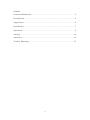
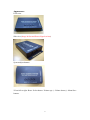
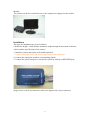
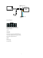
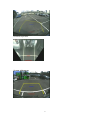
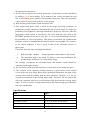
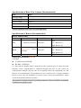
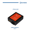
Image-based Driving Assistant System
User Guide
V1.0
Please read this guide carefully before using this system to ensure the driving safety
1
Contents
General Information ........................................................................ 2
Introduction ................................................................................... 2
Appearance .................................................................................... 4
Installation ..................................................................................... 7
Operation ....................................................................................... 9
Setting... ... ... .............................................................................. 10
Attention... ... ............................................................................... 12
Trouble Shooting .......................................................................... 12
2
General Information
Please read the following operation guide carefully. To avoid the possible driving
risks or the damages on this product, please use this product according the regulations
in this brochure.
-Use appropriate cords
-Please use specified connection cords provided in this product
-Please follow the settings in this brochure
-Don't remove the case or cover of the assemblies after purchase to avoid
being damped or damaged.
-Please keep the clean of the assemblies. Do not install the assemblies
exposed to the rain or fog directly.
Introduction
This driving assistance system is dedicated to providing assistant information
when the driver maneuvering his/her vehicle for backward parking. In general, with
the installments of the rear-view camera and the monitor, this system helps the driver
to steer by the dynamic parking trajectory on monitor given by the system. In
Addition, this product also can provide the overlook mode guidance for the
convenience of the driver to observe the environment. With the help of this system,
the possible accident or collision occurred during careless backward parking can be
avoided. The applicable environment of this product includes sunny day, the cloudy
day, night, dry and damped driving environment.
-Applicable weather conditions:Clear day、rainy day、cloudy day、night
-Applicable parking environment:Regular park area、underground park
area
-Applicable road condition:Tarmac、concrete、soil
Since the driving assistant is based on the image processing technology, therefore,
this system will fail to provide successful guidance under some specific conditions,
which are listed as follows.
-The camera is obstructed by heavy rain、snow、fog.
-The captured image is overexposed due to the light reflection.
-The lens is seriously contaminated or scratched.
-The camera is blocked by wall、tree、leaves and so on.
3
Appearance
Front view
Side view (Image In/Out and Power/Signal sockets)
System adjust buttons
*From left to right: Reset、Select button、Volume up(+)、Volume down(-)、Menu/Save
buttons.
4
Mainframe
The mainframe with the connection cords is shown in the following figure.
Connection cords
*From left to right: Image In/Out connector、image input connector (to camera)、
image output connector (to monitor)、Power/Signal connector
Camera
The applicable camera of this system can be the general commercial rear-view camera
(with view angle of 170 deg) or the original equipped camera of the vehicle.
5
Monitor
The monitor can be the commercial one or the original one equipped on the vehicle.
Installation
The steps for installment are given as follows.
1.Define the height、width and the inclination angle through measurement of the host
vehicle and the specifications of the camera.
2. Install the system and sensor in the defined position.
3. Connect the Image In/Out and Power/Signal cords to the mainframe.
4. Connect the signal pins and their corresponding signals.
5. Connect the system and power, activate the system by shifting to REVERSE gear.
Image In/Out cord (4-pin connector) and Power/Signal cord (10-pin connector)
6
Image In/Out Cord
(4Pin)
Mainframe
(B)
PAS
(Y)
Monitor
Camera
Power/Signal Cord
(10Pin)
System Diagram
9
7
5
3
1
10 8
6
4
2
Definition of the 10-pin connector
10-pin connector:
1.ACC
2.12V out
3.Ground
4.Activation signal from REVERSE gear
5.Activation signal from ultrasonic sensor
6.Activation signal from user
7.N/A
8.N/A
9.CAN High
10.CAN Low
7
3
1
4
2
4-pin connector
4-pin connector:
1. Image IN(red)
2. Image OUT(white)
3. Image IN(white)
4. Image OUT(red)
Caution:Let the technician to install this system if possible, inappropriate installment
may lead to abnormal operation
Operation
System on/off
The driving assistance system is activated when the driver shift to the REVERSE gear
and then the system is in guidance mode, where the rear-view image is shown on the
monitor. In this system, the operation can be divided into the guidance mode and the
system adjustment mode.
System Operation
8
Overlook Operation
System Adjustment
9
Setting
*From left to right: Select button、Volume up、Volume down、Menu/save buttons.
In this system, the adjustable parameters are 1) Height of the rear-view camera (H); 2)
Width of the vehicle (W); 3) Inclination angle of the rear-view camera ( θ ); 4)
Overlook mode activation condition (Mode).
1)Height of the rear-view camera (H)
Height ranges from 50(cm) to 200(cm),with the resolution of 5(cm)
2)Width of the vehicle(W)
Width ranges from 50(cm) to 200(cm),with the resolution of 5(cm)
3)Inclination angle of the rear-view camera ( θ )
Angle ranges from 10(deg) to 60(deg),with the resolution of 2(deg)
Width
Height
θ
10
4)Overlook mode activation condition (Mode)
The activation condition can be chosen as Sonic (ultrasonic radar-based)
activation and Image(image-based) activation
Sonic(ultrasonic radar-based) activation:The mode switch is handled by the
detected distance between the obstacles and the host vehicle.
Image(image-based) activation:The mode switch is handled by the estimated
distance between the obstacles detected from rear-view image and the host
vehicle.
Adjustment enable/disable button
During system operation, the operation mode switches to adjustment mode when user
pushes this button. Under the adjustment mode, pushing this button after parameter
adjustment can return to the operation mode.
Volume down(-)
Under the adjustment mode, pushing this button can reduce the specified parameter
(or switch the specified mode).
Volume up(+)
Under the adjustment mode, pushing this button can increase the specified parameter
(or switch the specified mode).
Switch
Under the adjustment mode, pushing this button can switch the specified parameter to
be adjusted.
11
Example
This figure illustrates the output image after the system adjustment is activated (by
press the MENU/SAVE button), where the height of the camera is set as 180cm (as
shown in sequences). When user presses the SELECT button several times the
overlook activation mode is shown and the overlook mode activation condition is set
as manual mode activation. When the volume button is pressed, the mode can be
changed to ultrasonic-based activation mode.
12
After the parameter adjustment is completed, press the MENU/SAVE button will
terminate the parameter adjustment process.
Attention
System Power
z Connect to the ACC power on vehicle: 8~16V DC power
z Connect to the REVERSE gear (or the REVERSE LIGHT +12V)
Camera Installment
z The installment position should be chosen according to the host vehicle. The
camera should be installed in the middle of the rear-side of the vehicle. Keep the
lens clean during operation to ensure the image quality.
z The power of the camera can be provided by mainframe (Pin 1 and pin 2)
Troubleshooting
Q: Why I can not activate the system after the installment?
A: This system turns on only when the vehicle is shifted to the REVERSE gear. Make
sure the gear stick is shifted to REVERSE position
Q: After turning on the system, why the output video is not shown normally?
A: This is because the synchronization failure between the system and the camera
when the system is activated. User can reset the system or re-shift the gear. If the
problem still exists, please contact with the technician for assistance.
Q: The overlook mode does not work when the ultrasonic sensors are activated.
A:1)please check the mode settings of the system is with ultrasonic-based activation.
(Mode: Sonic)
2)If the setting is corrected and the malfunction still occurs, please contact with the
technician to check the connection to the buzzer and the output of the ultrasonic
sensor for their correctness.
Q: The overlook guidance mode occurs when vehicle is under REVERSE gear and
the ultrasonic sensor can not trigger it.
A: There may be a connection error between the ultrasonic signal and mainframe. Ask
for the technician for assistance.
Q: Why the generated overlook image has deficient area? The generated image
possesses two black areas in the bottom-left and bottom-right part.
A: It is the inevitable result after the image transform, the generated black image areas
are the blind spots of the original image. If the user can not adapt to such
representation, he/she can ask the technician to rearrange the installation.
Q: If the user can not obtain the accurate installation height、inclination, how to adjust
13
the appropriate parameters?
A: If user can not capture the accurate parameters, an alternative system installation
by parking grid is also available. Try to maneuver the vehicle and make the grid
line of the parking space parallel to the generated trajectory. Then, the adjustment
can be achieved based on the grid line on the ground.
Q: Why the image-based mode switch sometimes fail?
A: The image-based mode switch is based on the image processing techniques to
estimate the possible obstacles to determine the time of mode switch. To reduce the
possibility of misjudgment, a learning mechanism is proposed. Therefore, when the
image-based mode switch is activated by the drive shift the gear stick at the
REVERSE position, he/she has to wait for 1~2 sec for system learning to increase
the possibility of correct recognition. This mode is used under the condition that
ultrasonic sensors is damaged and the manual switch is not available. The accuracy
of the switch judgment is not as good as that of the ultrasonic sensors or
observation.
The factors that may cause misjudgment includes:
1.
Reflected light、shadow、 damped ground or other marks on the ground.
2.
The inclination angle is too small. To achieve a successful installment, the
ground image should over 2/3 of the whole image.
We strongly recommend the ultrasonic-based and manual switch should be
considered with higher priority.
Q: The correctness of the generated trajectory is inaccurate at low backward speed.
A: The variation of the dynamic parking trajectory is given based on the motion
vector of the rear-view image. Based on the generated information, the angle of the
steering wheel and the parking path are thus generated. Therefore, it is not the
accurate measurement of the steering wheel angle. Therefore, the two factors that
affect the estimated trajectory are the maneuvering speed and the steering wheel
angle. To achieve a more accurate measurement, the maneuvering speed should be
take into consideration.
Specifications
Item
Spec.
Rated Current
0.25 A, (Camera not included)
Operation Voltage
8V~16V
Operation Current
Operation Temperature
0.16 A, (Camera not included)
-30℃~75℃
Storage Temperature
-40℃~85℃
14
Specifications of Rear-View Camera (Recommended)
Item
Viewing Angle
Spec.
D:150∘/H:105∘/V:83∘(*Note)
Power Supply
DC 12V
Power Current
0.095 A
Minimum Illumination
0.3 Lux/F1.2
Mode
NTSC/PAL
*In this system, the FOV:120/170 is also applicable
Specifications of Buzzer (Recommended)
Buzzer Sound Time
Buzzer OFF time
Buzzer ON time
Remarks
Slow
< 3*(Buzzer ON time) 75ms±5ms
Pulse
Low : Buzzer on
High: Buzzer off
Quick
Approximate
ON time
Pulse
Low : Buzzer on
High: Buzzer off
Continuing
0
Buzzer
75ms±5ms
∞ms
Other Specifications (OEM)
CAN Bus:
z CAN2.0A and CAN2.0B
z Bit Rate: 125(Kbit/s)
P.s.: The CAN bus interface mode is designed for some specified types of vehicle where the
ultrasonic sensor communication is conducted through CAN bus. In this system, the
communication through CAN bus can not be applied without the acquirement of CAN
protocol of the manufacturer. The installation by user on his/her own is strongly prohibited
because it may cause the instabilities of vehicle control systems and malfunctions. Please
counsel with specialist for their assistance.
This product is designed only for providing assistance. Drivers should be responsible
for his/her own safety on road
15