Download Bel 2120B User's Guide - Media
Transcript
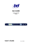
Bel 2120B
Analogue/AES/SDI
Shuffler
User’s Guide
Version 1.0 06/05/04
BEL DIGITAL AUDIO
Bel2120B
BEL (Digital Audio) Ltd. has made every effort to ensure the accuracy of information
contained within this document which is nevertheless supplied for information
purposes only and does not constitute any form of warranty or guarantee.
All trademarks acknowledged.
The information in this document is subject to change without notice.
Bel Digital Audio Ltd.
Unit 3
Horwood Court
Bletchley
Milton Keynes
Bucks
MK11RD
Tel: 01908-641063
Email: info @ beldigital.com
Web: www.beldigital.com
©
2004 BEL Digital Audio Ltd.
2
BEL DIGITAL AUDIO
Bel2120B
INTRODUCTION
5
FEATURES
Input Switching and routing
Inputs
Input Levels
Phase Reversal
Outputs
Monitor Outputs
Memory
Keyboard lock
5
5
5
5
5
5
5
6
6
Front panel controls
LCD Graphic Display
Nudge up/down ∧ ∨
SET
Input/Output
FAD
MAT
BYP
LOCK
Monitor level and output jack
6
6
6
6
6
6
7
7
7
7
FIG 1.1 BEL 2120B FRONT PANEL
8
FIG 1.2 BEL 2120B REAR PANEL
8
OPERATION
Matrix mode operation
Mixer mode operation
9
9
10
SETUP
Page 1. Memory functions
Page 2. Mode selection
Page 3. Headphone monitor source selection
Page 4. Input source selection
Page 5. SDI group selection
SDI output select
Analogue output select
AES output select
SDI video standard select
Ingroup deletion
Input levels/ Analogue input gain adjustment
Output levels/ Analogue output gain adjustment
Communications address
11
11
11
11
12
12
12
13
13
13
13
14
14
14
©
2004 BEL Digital Audio Ltd.
3
BEL DIGITAL AUDIO
Bel2120B
RS422 Serial control
15
Rear Panel Connectors
15
Pin Connections
EMC compliance
15
16
Specification Bel Model 2120B
SDI I/O
Analogue Inputs
Analogue outputs
AES-EBU Digital I/O
General
The Bel2120B Serial Protocols
Overview
Frame format
Commands
General data format
17
17
17
17
17
17
18
18
18
19
20
APPENDIX A
2120B operational description
21
21
©
2004 BEL Digital Audio Ltd.
4
BEL DIGITAL AUDIO
Bel2120B
BEL 2120
SDI Shuffler
INTRODUCTION
The Bel 2120 can process any combination of analog, AES or SDI audio signals and
simultaneously output the result in any of these formats. The audio can be routed,
mixed, inverted and level shifted. A headphone monitor jack is also provided on the
front panel.
The unit can be controlled by front panel switches or remotely.
Features
Input Switching and routing
The unit can operate in one of two main modes, Matrix or Mixer. In the Matrix
mode available audio input can be selected, modified and directed to any output. In
the Mixer mode any combination of inputs can be selected, mixed and directed to any
output. (See operational detail)
Inputs
The inputs accepted by the Bel2120 are organized in pairs. Input pairs from
analog, AES or SDI (any group) can be accepted.
Input Levels
In either mode gain can be applied to the selected inputs before redirection or
mixing. The gain can be adjusted over the range +10 to -30 dB.
Phase Reversal
In either mode the selected inputs can be phase reversed before routing or
mixing.
Outputs
The BEL 2120 provides simultaneous analog, AES and SDI (any group)
outputs.
Monitor Outputs
A stereo headphone output is provided on the front panel to allow any
pair of outputs to be monitored. The signals on the left and right monitor outputs can
be selected via the setup system.
©
2004 BEL Digital Audio Ltd.
5
BEL DIGITAL AUDIO
Bel2120B
Memory
The operating mode and current setup are stored in one of eight memories.
This information is retained when the unit is switched off. The memory can be reset to
the factory default settings by depressing the set key while the BEL logo is displayed
at power on.
Keyboard lock
Inadvertent operation of the keys can be avoided by invoking the key ‘lock’
function.
Front panel controls
Several push buttons and indicators are located on the front panel, Fig 1.1, from left to
right these are:
LCD Graphic Display
On power-up the LCD will show model number, software version and model
description for a few seconds before resetting to the default display. In its default
mode the LCD will display:
• Current input to output connections
• Gains and phase reversal settings for each input
• Memory number
• State of the FAD, MAT, BYP and LOCK switches
Nudge up/down ∧ ∨
These buttons are used to adjust input gains when the default screen is visible
and the value of parameters within the setup menus.
SET
This key will enter the setup menus. See setup section for details of this
operation.
Input/Output
Two horizontal rows of switches control the input and output selection. The
upper row marked 1 to 4 are the input selection switches. The lower row are the
output selectors. A red LED indicator positioned beneath each input switch will show
the currently active input channel. See below for detail of their use.
FAD
This switch is only functional in the matrix mode and can be used to override
any gain adjustments imposed on the input audio. If the character F is not shown in
inverse video on the right hand side of the LCD display all inputs are passed to the
selected outputs without gain adjustment. The gains shown on the LCD will be
©
2004 BEL Digital Audio Ltd.
6
BEL DIGITAL AUDIO
Bel2120B
contained in outline boxes. These values can be adjusted but the gain variation will
not take effect until the FAD switch is activated.
MAT
This switch is only functional in the matrix mode and can be used to override
any redirection imposed on the input audio. If the character M is not shown in inverse
video on the right hand side of the LCD display all inputs are passed to their
appropriate output. i.e. in 1 to out 1, in 2 to out 2 etc. The discs connecting input lines
to output lines will be replaced by outline squares. The position of these connections
can be adjusted but the actual input/output assignment will not be made until the
MAT switch is activated.
BYP
This switch will activate an electronic bypass and is a combination of FAD
and MAT. No gain adjustment or redirection of the inputs occurs when the character
B is shown in inverse video on the right hand side of the LCD display.
LOCK
When the unit is ‘locked’ all the front panel keys, except LOCK, are
inoperative. To release the keys press and hold the LOCK key for a period in excess
of five seconds. A momentary press of the LOCK key will again place the unit in the
lock mode. The locked mode is indicated by the character L shown in inverse video
on the right hand side of the LCD display.
Monitor level and output jack
The headphone monitor output is available from this 6 mm stereo Jack. The
outputs to this jack can be selected in the setup menus; the audio level is set by the
small knurled control.
©
2004 BEL Digital Audio Ltd.
7
BEL DIGITAL AUDIO
Bel2120B
Fig 1.1 Bel 2120B Front panel
Fig 1.2 Bel 2120B Rear panel
©
2004 BEL Digital Audio Ltd.
8
BEL DIGITAL AUDIO
Bel2120B
OPERATION
The BEL 2120 Shuffler can operate in either the Matrix or the Mixer mode.
Matrix mode operation
In the quad matrix mode of operation each of the four output channels can
have one of the inputs associated with it. The inputs can be derived from the SDI ,
AES or analog inputs. The gain and phase of each input can be modified, depending
on the state of the FAD, MAT and BYP controls, before being passed to the output.
The LCD display, in this mode, shows the 4 output channels, their associated input
and its gain or phase modification.
To operate in the quad matrix mode first ensure that quad matrix is selected in
the setup menu. The Matrix modes can be confirmed if the amber LED to the right of
input switch 4 is extinguished. Then select the OUTPUT required by depressing the
appropriate numbered switch on the lower horizontal row. The output selected will be
indicated by a solid line on the matrix on the LCD display, the current input channel
associated with this output is indicated by the LED. If required the input channel can
now be changed by depressing the required switch on the upper row. The level of that
channel can be adjusted by depressing the nudge ∧ ∨ keys, the current level in dBs
will be shown on the LCD display. A phase reversal can be applied to the input
channel by depressing the INV switch. The phase reversal is indicated by a ↓ symbol
on the LCD display positioned beside the corresponding output.
The dual matrix mode is identical to the quad matrix mode except that level
adjustments are applied to pairs of inputs. This feature facilitates accurate tracking of
stereo pairs. The dual matrix mode can be selected in the setup menu.
©
2004 BEL Digital Audio Ltd.
9
BEL DIGITAL AUDIO
Bel2120B
Mixer mode operation
The mixer mode, identified by the amber LED, provides the facility to select
and mix a combination of any inputs and direct the result to any output. As with the
Matrix mode, gain and phase reversal can be applied to the selected inputs. In this
mode the LCD display will show a different screen for each output selected. The
display will indicate the level and phase reversal of each input together with the
current input for adjustment.
To operate in the Mixer mode first ensure that Mixer is selected in the setup
menu. The amber LED to the right of input switch 4 is active. Then select the output
required by depressing the appropriate numbered switch on the lower horizontal row.
The page corresponding to the output selected will be shown on the LCD display, the
current input channel is indicated by the corresponding LED and on the LCD. If
required, the input channel for adjustment can now be changed by depressing the
required switch on the upper row. The level of that channel can be adjusted by
depressing the nudge ∧ ∨ keys, the current level will be shown in dBs on the LCD
display. A phase reversal can be applied to the input channel by depressing the INV
switch. The phase reversal is indicated by a ↓ symbol on the LCD display positioned
beside the corresponding input.
Note that the FAD, MAT and BYP buttons are inoperative in this mode.
©
2004 BEL Digital Audio Ltd.
10
BEL DIGITAL AUDIO
Bel2120B
Setup
The setup function of the 2120 is accessed by depressing the SET key.
Parameters adjustable under setup can be made to appear sequentially by repeatidly
depressing the SET key. Each of the setup menus, with the exception of the memory
recall, show values that can be adjusted by means of the nudge ∧ ∨ keys. The setup
menu will time-out after 30 seconds if no adjustment is made. The functions available
in setup are as follows:
Page 1. Memory functions
The first press of the SET key will enter the memory recall state. The word
PROG on the lower portion of the LCD will flash. It is possible to browse the states of
the 8 memories by pressing the input and output selection switches. Input switches 1
to 4 will display the memory settings 1 to 4, output switches 1 to 4 will display the
memory settings 5 to 8. The memory setting are merely displayed up to this point, to
activate a particular memory first select the required number as described above and
then hit the same switch a second time.
Page 2. Mode selection
The operational mode of the unit, Quad Matrix, Dual Matrix or Mixer may be
selected here. The Nudge buttons makes the selection.
Page 3. Headphone monitor source selection
The output directed to the left or right headphone monitor channel can be
selected here. To select a channel for the right monitor source press the SET key and
then make a selection, to return to the left monitor source press the input 1 key.
©
2004 BEL Digital Audio Ltd.
11
BEL DIGITAL AUDIO
Bel2120B
Page 4. Input source selection
The audio source selection is organized in pairs. The source channel for inputs
1/2 and then 3/4 can be selected here. The possible sources are SDI 1/2, SDI 3/4, AES
1/2, AES 3/4 Analog 1/2 or Analog 3/4. To select the input 3/4 source press the SET
key and then select the required input source using the ∧ ∨ keys, to return to the input
1/2 source press the input 1 key.
Page 5. SDI group selection
The input and output SDI group can be selected here. To select an output
group press the SET key and then make a selection, to return to the input group
selection press the input 1 key. The 2120 can accept SDI inputs on one group and
embed outputs on another. The incoming embedded audio can be retained or deleted
as described below.
SDI output select
The SDI outputs can be connected, in pairs, either to the SDI inputs (not
shuffler inputs) or shuffler outputs
©
2004 BEL Digital Audio Ltd.
12
BEL DIGITAL AUDIO
Bel2120B
Analogue output select
The 4 analogue outputs can be connected to either the Shuffler inputs or
outputs and this can be selected here. Depress set again to select AES outputs.
AES output select
The AES outputs can be connected to either the Shuffler inputs or outputs and
this can be selected here. Depress the 1 input button to return to analog select.
SDI video standard select
The SDI de-multiplexer can accept PAL or NTSC video standards. These can
be selected here.
Ingroup deletion
The incoming group selected by the shuffler can be deleted or retained. This
facility can be selected here. If the incoming and outgoing groups are the same the
shuffler will automatically delete the incoming group.
©
2004 BEL Digital Audio Ltd.
13
BEL DIGITAL AUDIO
Bel2120B
Input levels/ Analogue input gain adjustment
The left hand half of the LCD display carries an indication of the level of the
inputs to the Shuffler. Note that these may come from SDI, AES or analogue sources.
The right hand half of the screen allows the ANALOGUE INPUT GAIN to be
adjusted. This setup menu item will not time out to give the opportunity for setting
levels.
Output levels/ Analogue output gain adjustment
The left hand half of the LCD display carries an indication of the level of the
outputs from the Shuffler. The right hand half of the screen allows the ANALOGUE
OUTPUT GAIN to be adjusted. This setup menu item will not time out to give the
opportunity for setting levels.
Communications address
This allows the address of the unit to be selected. The unit will only respond to
serial commands that contain its address. The permitted range of addresses is 1 to 100.
©
2004 BEL Digital Audio Ltd.
14
BEL DIGITAL AUDIO
Bel2120B
RS422 Serial control
The BEL 2120 can be externally/ remotely controlled via the 9 pin RS422
socket on the rear panel. Units can be connected in cascade by linking the RS422
output connector of one unit to the RS422 input connector of the next. The RS422
signal is buffered by each unit and electro-mechanically bypassed during power
down. When a recognized RS422 data word is received the BEL 2120B front panel
will be locked out to avoid confusion.
Rear Panel Connectors
From the left these are:
Analogue inputs (upper)
Analogue outputs (lower)
SDI input
SDI output
AES I/O
RS422 in serial Port
RS422 out serial Port
Mains power
15 way D female
15 way D female
BNC 75ž
BNC 75ž
15 way D female
9 Pin D female
9 Pin D female
230/115VAC IEC 3 Pin
A mains switch and fuseholder (230V - 250mA, 115V 500mA)
Pin Connections
Audio inputs
Pin1 Ch1 +
Pin 2 Ch1 Pin 3 Ch2 +
Pin 4 Ch2 Pin 5 Ch3 +
Pin 6 Ch3 Pin 7 Ch4 +
Pin 8 Ch4 Audio outputs
Pin1 Ch1 +
Pin 2 Ch1 Pin 3 Ch2 +
Pin 4 Ch2 Pin 5 Ch3 +
Pin 6 Ch3 Pin 7 Ch4 +
Pin 8 Ch4 -
©
Pin 9
Pin 10
Pin 11
Pin 12
Pin 13
Pin 14
Pin 15
GND
GND
GND
GND
GND
GND
GND
Pin 9
Pin 10
Pin 11
Pin 12
Pin 13
Pin 14
Pin 15
GND
GND
GND
GND
GND
GND
GND
2004 BEL Digital Audio Ltd.
15
BEL DIGITAL AUDIO
AES I/O
Pin 1
Pin 2
Pin 3
Pin 4
Pin 5
Pin 6
Pin 7
Pin 8
RS422 IN
Pin 1
Pin 2
Pin 3
Pin 4
Pin 5
RS422 OUT
Pin 1
Pin 2
Pin 3
Pin 4
Pin 5
Bel2120B
Ch1/2 + Out
Ch1/2 -Out
Ch3/4 +Out
Ch3/4 - Out
Ch1/2 + In
Ch1/2 - In
Ch3/4 + In
Ch3/4 +-In
Pin 9
Pin 10
Pin 11
Pin 12
Pin 13
Pin 14
Pin 15
GND
GND
GND
GND
GND
GND
GND
Chassis
Tx Rx +
GND
GND
Pin 6
Pin 7
Pin 8
Pin 9
GND
Tx +
Rx Chassis
Chassis
Rx Tx +
GND
GND
Pin 6
Pin 7
Pin 8
Pin 9
GND
Rx +
Tx Chassis
It is recommended that, where possible, all cables be good quality screened
twisted pairs with the screening braid connected to pin 1 on the XLR connector.
Optimum performance is obtained using double screened cable with separate ground
returns. It is also recommended that 360 degree connection be made to the screening
braid on the BNC connectors. Screened ‘D’ type connectors are also recommended.
EMC compliance
The BEL 2120 was designed and tested to comply with the EMC directive
numbers EN55103, EN55022 and EN55082-1 when used as directed.
CE
©
2004 BEL Digital Audio Ltd.
16
BEL DIGITAL AUDIO
Bel2120B
Specification Bel Model 2120B
SDI I/O
InputsI/O
Serial component digital video signal 4:2:2, to SMPTE 259M
4 Channels from SDI(Groups 1 to 4). SMPTE 272M-A
Analogue Inputs
Inputs
A/D
Level
Noise
Bandwidth
Input impedance
4 channel differential
24 bit x 64 oversampled
+6dB in for –9dB Digital. (max 15dB)
-105 dB wrt. Max input (Audio precision weighted 20Hz to
20kHz)
20Hz to 20kHz ± 0.5dB
25kΩ differential
Analogue outputs
Outputs
D/A
Level
Output impedance
Noise
Bandwidth
4 Channels Differential
24 bit
+6dB out for –9 dB digital in.(Max 15dB)
50 Ω
-110dB wrt. Max output (Audio precision weighted 20Hz to
20kHz)
20Hz to 20 kHz ± 0.5dB
Monitor output
2 channel analogue with source selector, min 8 Ω
AES-EBU Digital I/O
Input
Output
2 pairs AES-EBU 32 to 50 ks/sec
2 pairs AES-EBU 48 ks/sec
General
Remote interface
Power requirements
Power consumption
Dimensions
Net weight
©
RS422, 9.6kBaud
96/265 VAC 50/60 Hz
40W
428w x 44h x 20d (1U)
7kg
2004 BEL Digital Audio Ltd.
17
BEL DIGITAL AUDIO
Bel2120B
The Bel2120B V2.0 Serial Protocols
Overview
Commands to be communicated to the remote unit (2120) are arranged in
frames. These frames will then be sent to the remote unit which will always reply with
either ACK for acceptance or NAK for rejection. Any requested reply then follows in
the same frame format.
Frame format
Start Flag
0XAA
Destination Address
Source Address
Command
Data Count
Data
Checksum
End Flag
0XFE
The frame starts with a start character 0XAA which is alternating ones and
zeros. This is followed by the destination address, the source address, the command
code, the data count, the data, a checksum and an end flag 0XFE.
Start Flag
The start flag 0XAA may be sent at any time. If sent during a frame this will
effectively cause the frame to restart.
Destination Address
This should be set to the same as the comms address for the target 2120. This
will be returned by the remote unit as the source address.
Source Address
This should be set to 1 for 2120. This will be returned by the remote unit as
the destination address.
Command
This character is the command for the remote unit and must fall in the range
0X80 to 0XEF. More details of the relevant codes are shown below.
Data count
This is the total number of data bytes following, up to a maximum of 127.
Data
The data required for the command is carried here. Each character can have a
value of 0X00 to 0X7F i.e. 7 bits.
Checksum
This is the modulo 7 sum of characters in the frame between the destination
address and the last data character inclusively. It is calculated thus:
DO
{
checksum = (character+checksum) AND 0X7F
}
©
2004 BEL Digital Audio Ltd.
18
BEL DIGITAL AUDIO
Bel2120B
FOR ALL CHARACTERS IN FRAME
End Flag
A character 0XFE ends the frame.
Commands
Commands to the 2120:
Code
(Code
Code Function
(hex)
Reply
80
Prompt for reply
81
Use first data char as a second command
C0 – ACK (OK)
C1 – NAK (send again)
ACK
82
Request unit identifier
ACK then C2
85
ACK
87
Send program number. Data count =1 then program
number 0-7.
Request program number
8C
Parameter reset
ACK
8D
Send 16 input gains. Data count=16 then 16 gain
values as below
Request 16 input gains
ACK
ACK
90
Send general data. Data count=6 then data as
below
Request general data.
91
Send output gains. Data count=4 then 4 gain values
ACK
92
Request output gains
ACK then D2
93
Send 1 input gain value. Data count=1 then input
number and then gain value
Send mode. Data count =1 then mode value.
ACK
8E
8F
94
ACK then C7
ACK then CE
ACK then D0
ACK
(Hex) Function Reply
Replies
Replies, when requested (e.g. 82), will consist of frames that contain the
original command value plus 0X40. So a request for an ident, 0X82, will elicit a reply
of ACK then a frame containing 0XC2 and the ident string.
©
2004 BEL Digital Audio Ltd.
19
BEL DIGITAL AUDIO
Bel2120B
General data format
The send and request general data (8F, 90) commands communicate most
switch settings to PC and 2120. The format for these is:
Bit 7
Bit 6
Bit 5
Msb of
bit 4
Bit 4
Input for
out 3
Matrix
mode
Bit 3
Msb of
bit 2
Byte 1
Msb of
bit 5
Current
output
Msb of
bit 3
Current
input
Byte 2
Video
mode
Msb of
bit 4
Left
monitor
source
Remote
Lock
Byte 3
Msb of
bit 4
Output
SDI
group
Byte 4
Msb of
bit 3
Byte 0
Byte 5
Xfade
SDI
3,4output
source
SDI 1,2
output
source
Bit 2
Input for
out 2
matrix
mode
Bit 1
Msb of
bit 0
Bit 0
Input for
out 1
matrix
mode
Msb of
bit 0
Input for
out 4
Matrix
mode
Byp
Mat
Fad
Msb of
bit 2
Input
SDI
group
Msb of
bit 0
Right
monitor
source
3,4 Input
source
Msb of
bit 0
Dual
mode
Mat mix
mode
1,2 Input
source
Analogue
output
source
AES
output
source
it 6 Bit 5 B
t4
Bit 3 Bit 2 Bit 1 Bit 0
Gain value format.
The data sent or received as gain values are formatted as follows: Channel one first.
Gain range +10dB to –30 dB value = 50 to 10 respectively
Value of 9 mutes that channel.
Where more than one bit is required such as Group number, the second bit is
labeled Msb of bit n.
RS422 format: 8 data bits, no parity, two stop bits, 9600 Baud.
.
©
2004 BEL Digital Audio Ltd.
20
BEL DIGITAL AUDIO
Bel2120B
Appendix A
2120B operational description
The signal routing capabilities of the 2120B is shown in Fig 2.0
The LCD display in matrix mode was generated for ease of use but does not
literally describe the operation of the 2120. Each output has 4 independent level
adjustments associated with it. These adjustments are actually on the inputs not on the
outputs as shown on the LCD. Inversion is also done on the inputs not outputs. As
there is only one input routed to each output whether the level is set on input or output
would seem to be academic. However, the effect of this can be seen by selecting one
output and then setting different levels for each input. Changing the input select for
this output then restores the set level value. Each output is independent so there are in
effect 16 level settings in the 2120. Fig 2.1 Similarly the mixer mode has 16 level
adjustments (independent from the matrix gains). Fig 2.2
Fig 2.0
©
2004 BEL Digital Audio Ltd.
21
BEL DIGITAL AUDIO
Bel2120B
Fig 2.1
©
2004 BEL Digital Audio Ltd.
22
BEL DIGITAL AUDIO
Bel2120B
Fig 2.2
©
2004 BEL Digital Audio Ltd.
23


