1
2
Filter Design
Filter Requirements and Specification
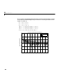
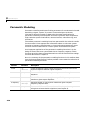
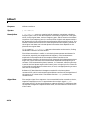
The Signal Processing Toolbox provides functions that support a range of filter
design methodologies. This chapter explains how to apply the filter design tools
to Infinite Impulse Response (IIR) and Finite Impulse Response (FIR) filter
design problems.
The goal of filter design is to perform frequency dependent alteration of a data
sequence. A possible requirement might be to remove noise above 30 Hz from
a data sequence sampled at 100 Hz. A more rigorous specification might call for
a specific amount of passband ripple, stopband attenuation, or transition
width. A very precise specification could ask to achieve the performance goals
with the minimum filter order, or it could call for an arbitrary magnitude
shape, or it might require an FIR filter.
Filter design methods differ primarily in how performance is specified. For
“loosely specified” requirements, as in the first case above, a Butterworth IIR
filter is often sufficient. To design a fifth-order 30 Hz lowpass Butterworth
filter and apply it to the data in vector x,
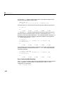
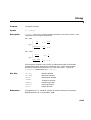
[b,a] = butter(5,30/50);
y = filter(b,a,x);
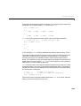
The second input argument to butter indicates the cutoff frequency,
normalized to half the sampling frequency (the Nyquist frequency).
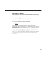
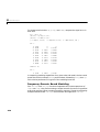
Frequency Normalization in the Signal Processing Toolbox All of the filter
design functions operate with normalized frequencies, so they do not require
the system sampling rate as an extra input argument. This toolbox uses the
convention that unit frequency is the Nyquist frequency, defined as half the
sampling frequency. The normalized frequency, therefore, is always in the
interval 0 ≤ f ≤ 1. For a system with a 1000 Hz sampling frequency, 300 Hz is
300/500 = 0.6. To convert normalized frequency to angular frequency around
the unit circle, multiply by π. To convert normalized frequency back to Hertz,
multiply by half the sample frequency.
2-2