1
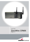
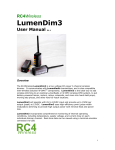
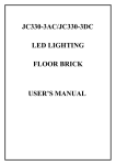
CRMX user guide
Wireless DMX/RDM
Front panel controls
Lighting control via wireless is nothing new, there are plenty of
options. Trouble is, everyone is using the same narrow band
of frequencies, and not just for lighting. Your competition are
wireless microphones, in-ear monitors, Wi-Fi, ZigBee, Bluetooth
devices and many more - often at the same time.
To achieve true wireless link reliability, you need an ingenious
approach: CRMX™ (Cognitive Radio MultipleXer) provides the
answer. Using our Cognitive Coexistence system at its heart,
CRMX continually monitors the whole frequency band to identify all problem areas and dynamically shifts its operation. The
result is that CRMX neither disturbs, nor is disturbed by other
systems - it totally coexists, even in the most crowded areas.
CRMX units use high frame refresh rates and intelligent error
correction routines to fix problems before they ever become
apparent. CRMX units are so efficient that they can repair most
corrupted or mis-timed inputs from other devices - a kind of
DMX washing machine to clean up dirty signals.
CRMX units are available as single transmitters and receivers
which support DMX-512A/RDM, or as a dual transmitter which
can send two DMX/RDM universes and additionally supports
Art-Net and Streaming ACN via its Ethernet connection. As a
useful bonus, the dual unit can also convert between Art-Net/
Streaming ACN and standard DMX/RDM via the wireless and
wired connections.
Each unit uses an indicator panel to control and report upon its
operation. See the operation section for details on how to link
and unlink CRMX unts.
Connect - press to link with,
Lock - lit when keylock is locked.
Power - lit when power applied.
or unlink from, another unit.
RF Link
Connect
DMX
RDM
USB
Lock Power
Ethernet
Signal strength indicators
Not used on transmitters. For
receivers, the amber indicator
turns on at roughly 20% of
maximum signal strength and
the top green indicator turns
on at roughly 90%. The red
indicator turns on only if a
problem occurs with the link
to the transmitter.
Status indicators
RF Link: Indicator on when this unit is linked.
Receiver: Flashes fast (~3Hz) if link is lost or
when linking. Transmitter: Flashes fast (~3Hz)
when linking or slow (~1Hz) when unlinking.
DMX: On when a DMX signal is present.
RDM: Flashes to show RDM packet activity.
USB: On when connected via USB.
Ethernet: Flashes to show Art-Net/Streaming
ACN activity.
Rear panel connections
Dual CRMX transmitter unit
Ethernet socket - Art-Net, Str. ACN, etc.
(also supports Power Over Ethernet)
USB socket
for future upgrades
5-pin male XLR socket
DMX512A for port A
5-pin male XLR socket
DMX512A for port B
85-264VAC
power input
12VDC power input
Polarity is unimportant
Note: If Power Over Ethernet is used, do not also attach 12VDC or mains power.
Single CRMX transmitter
or receiver unit
12VDC power input
Polarity is unimportant
5-pin XLR socket
(male on TX, female on RX)
DMX512A input or output
85-264VAC
power input
Normal operation
To link units
1 Ensure the antennas are connected on the front panels.
2 Power on the transmitter and receiver(s). Ensure that the
RF LINK indicators on all receivers are off (use the unlink
procedure if necessary).
3 On the transmitter, press and release the CONNECT button.
The transmitter will search (for a period of ten seconds) for
unlinked receivers. Its RF LINK indicator will flash.
At the end of the search period, all located receivers will be
linked to the transmitter - their RF LINK indicators will be on.
To unlink units
• Unlink all: Press and hold the CONNECT button on the transmitter to unlink all of its receivers.
• Unlink one: Press and hold the CONNECT button on a receiver
to unlink it from a transmitter.
Art-Net and Streaming ACN configuration
The dual transmitter unit can process Art-Net and Streaming ACN signals via its Ethernet connection. Using the Sand Device Browser
utility on a computer linked to the same network as the CRMX unit, you can determine how signals should be directed and used.
The two CRMX ports operate independently; each port can be fed from or to any of 256 specific universes, via the Ethernet connection. The CRMX unit can act as a converter between Art-Net/Streaming ACN and the wired and/or wireless DMX connections.
To configure Art-Net and streaming ACN (dual units only)
1 Run the Sand Device Browser utility (from LumenRadio.com) on
a computer linked to the same network as the CRMX unit.
If there are two or more CRMX units, right click on one of the
entries in the utility and click the Identify option. The associated
CRMX unit will flash its indicators to identify itself.
2 If necessary, change the default Ip address of the CRMX unit. If
Ip is changed, double click on the Ip address window to reset
the unit (or power cycle the unit to achieve the same result).
3 For each CRMX port, choose the Mode (see panel right) and
the appropriate Protocol: Art-Net or Streaming ACN.
4 Choose the required Subnet (1 to 16) and the appropriate
DMX Universe (1 to 16) within that subnet. Set the IP address
for the CRMX unit
Mode
Disabled - Normal
operation only,
between the XLR
socket and the
wireless output.
Set mode and
protocol for
port A
DMX In - Signal
from XLR socket
is sent to Ethernet
socket as well as
wireless output.
Set the subnet
and universe
for port A
Set mode and
protocol for
port B
DMX Out - Signal
from Ethernet
socket is sent to
XLR socket and
wireless output.
Set the subnet
and universe
for port B
T-screw mounting
Each CRMX unit is supplied with two T-screws and
nuts to allow it to be securely fixed to any mounting
points, such as trussing.
To use a T-screw
1 Lower the T-screw into the slot on the side of the
unit and then twist it clockwise to lock.
2 Place the rectangular nut onto the screw.
3 Turn the nut clockwise until it tightens across the
slot, thus locking the T-screw securely within the
slot.
4 You can now attach the unit to a secure
mounting point. The T-screw is a
size M8 bolt.
CRMX RDM controller
CRMX RDM controller (with instructions) is available for download from
LumenRadio.com to be used with the
RDM transmitters.
3
2
1
EU Declaration of Conformity
Marking by the above symbol indicates
compliance with the Essential Requirements
of the R&TTE Directive of the European Union
(1999/5/EC). This equipment meets the following
conformance standards:
EN 301 489-1; 301 489-17; EN 300-328-1;
EN 300-328-2; EN 609 50
Release 1.0b August 2009
LumenRadio AB, Stena Center 1, S-412 92 Gothenburg, Sweden • www.lumenradio.com
Phone: +46-31-772-8084 • Fax: +46-31-772-8091 • Email: [email protected]