1
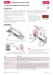
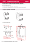
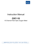
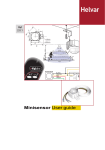
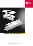
F13 102 1D 05/06
Minisensor2 User guide
lighting the way forward
Minisensor2 user guide - F13 102 1D 05/06
Introduction
The Helvar Minisensor2 is a two channel luminaire-mounted
component containing three integrated sensors:
• Presence detector (PIR)
• Constant light sensor
• Infrared (IR) receiver.
The two separate channels (A & B) enable scene setting
& lighting control. The constant light sensor only adjusts
the output from channel A, where presence detection
& infrared control affect both channels.
The Minisensor2 is only compatible with the Helvar EL-si
electronic DALI ballast range. Sensor set-up & programming is
achieved using the Helvar DIGIDIM infrared remote control.
Reception areas
Presence detector (PIR)
Orientation (PIR)
Infrared (IR) control
Constant light sensor (pipe version)
“Out-of-box” operation
Upon first application of power the Minisensor2 operates
according to the programmed memory of the EL-si ballast. If the
ballast has no program then the IR buttons “ ” , “ ” and “0/1”
(On/Off) will be active. Channel control is also active. This allows
the control of channels A&B (please see section “IR-control” for
more information). To program default scenes 1-4 and to activate
further features, please see the “Initial configuration” section for
more information.
Use the Helvar DIGIDIM infrared remote control for configuration.
2
Data subject to change without notice. For more information visit our website: www.helvar.com
Minisensor2 user guide - F13 102 1D 05/06
Initial configuration (default settings)
Select the operating modes by pressing the below mentioned button combination
for about 10 seconds. The product confirms the succesful programming by
flashing the lamps
“0/1” + ”1”
Presence detector (PIR) delay times 15min/20s, PIR on 100%, Power on 100%
“0/1” + ”2”
PIR 15min/20s, Manual On Auto Off, Power on 100%
“0/1” + ”3”
PIR 15min/20s, PIR on 100%, Constant light (*, Power on 100%
“0/1” + ”4”
PIR 15min/20s, Manual On Auto Off, Constant light (*, Power on 100%
*Dim the lights to desired constant light level before selecting the operating mode
Default values for operating modes
Scene 1
Scene 2
Scene 3
Scene 4
PIR ON light level
PIR LOW light level
PIR OFF light level
100%
75%
50%
25%
100%
1%
0%
PIR LOW delay
PIR OFF delay
PIR Exit delay
Power ON level
Fade time
15 min
20 sec
15 min
100%
1.0 sec
Notes:
• Only the light level of channel A will vary in order to try to keep the stored overall constant light
level.
• Constant light will not switch lighting on or off.
• The stored constant light level is not affected by the PIR.
• The stored constant light level is not affected by switching the lights off.
• “Manual ON, Automatic OFF” feature = PIR will not switch the lights on when movement is
detected, but will switch them off if no movement is detected.
• Regardless of other light level commands (e.g. changes in the constant light level), an enabled
PIR will switch the lights to the PIR OFF scene if no movement is detected within its programmed
delay time.
Infrared (IR) control
C A “0/1” (ON/OFF) key.
Toggles the lighting between 100%*) and OFF.
B “1”, “2”, “3” or “4” key.
Recall of stored scene or preset level for the selected key.
C “ ” key. Single push.
• Switches channel A & B on to minimum(if lights were off).
B
• Steps up channel A & B by one step (if lights were on).
Press & hold.
• Dims up channel A & B from minimum (if lights were off).
A
• Dims up channel A & B from last level (if lights were on).
D “ ” key. Single push.
D
• Steps down channel A & B by one step (if lights were on).
Press & hold.
• Dims down channel A & B from last level (if lights were on).
*) If constant light has been selected and programmed the Minisensor2 will dim the lights to the
programmed constant light level.
Modify and store scenes (channel A & B)
• Simultaneously press & hold “1” & “ ” or “ ” to raise or lower the light level of channel A to the
desired level.
• Simultaneously press & hold “2” & “ ” or “ ” to raise or lower the light level of channel B to the
desired level.
• Press & hold (for 10 seconds) the desired remote control scene button (“1”, “2”, “3” or “4”) where
you would like the scene to be stored.
• The operation is confirmed by flashing the lamps.
• Repeat the above for other scenes. (buttons “1”, “2”, “3” or “4”)
Notes:
• Scene is a combination of light levels of channel A and B that can be recalled by the press of a button.
• Storing scenes on buttons “1”, “2”, “3” or “4” will replace any previously stored light levels.
Data subject to change without notice. For more information visit our website: www.helvar.com
3
Minisensor2 user guide - F13 102 1D 05/06
Optional functions programming
Select the operating modes by pressing the below mentioned button combination for about
10seconds. The product confirms the succesful programming by flashing the lamps.
Presence detector (PIR)
Light level
Light level
ON
ON
15/30 min
1min
LOW
LOW
30 min
20s
OFF
PIR LOW delay
PIR OFF delay
Standard PIR delay funtionality
t
OFF
PIR LOW delay
PIR OFF delay
t
Corridor/storage room functionality
Set PIR ON scene
Select the overall desired light level: -See Infrared (IR) control section.
10s
• Simultaneously press & hold “0/1” for 10 seconds.
• The operation is confirmed by flashing the lamps.
Set PIR LOW scene
Select the overall desired light level: -See Infrared (IR) control section.
10s
• Simultaneously press & hold “0/1” &“” for 10 seconds.
• The operation is confirmed by flashing the lamps.
Set PIR OFF scene
Select the overall desired light level: -See Infrared (IR) control section.
10s
• Simultaneously press & hold “0/1” & “ ” for 10 seconds.
• The operation is confirmed by flashing the lamps.
PIR delay time setting
10s
Standard PIR delay functionality with 30min delay to PIR LOW scene
and 20s delay to PIR OFF scene.
• Simultaneously press & hold “3” & “ ” for 10 seconds.
• The operation is confirmed by flashing the lamps.
10s
Corridor / storage room functionality with 1min delay to PIR LOW
scene and 30min delay to PIR OFF scene.
• Simultaneously press & hold “3” & “ ” for 10 seconds.
• The operation is confirmed by flashing the lamps.
Notes:
• Regardless of other light level commands (e.g. changes in the constant light level), an enabled
PIR will switch the lights to the PIR OFF scene if no movement is detected within its programmed
delay time.
• PIR scenes can be any combination of light levels of channels A & B.
• If you manually turn lights off you might have to manually switch them on, PIR will not switch lights
on until PIR LOW delay (PIR Exit delay)
4
Data subject to change without notice. For more information visit our website: www.helvar.com
Minisensor2 user guide - F13 102 1D 05/06
Last level function
10s
• Simultaneously press & hold “4” & “ ” for 10 seconds.
• The operation is confirmed by flashing the lamps.
• If last level function is enabled, the lights will turn on to the level they
were at before mains interruption (failure or mains switch). Lights that
were off will remain off
• Last level function is deactivated by carrying out Initial configuration.
Test mode
This mode should only be used to test the functionality during installation. In Test mode PIR delay
times are 10 times faster and the constant light response time is 10 times quicker than in normal
operation and should only be used for demonstration or test purposes.
10s
• Enable: Simultaneously press & hold “4” & “ ” for 10 seconds.
(The operation is confirmed by flashing the lamps twice.)
• Disable: Simultaneously press & hold “4” & “ ” for 10 seconds.
(The operation is confirmed by flashing the lamps)
• Test mode is returned to normal mode by turning power off and
on again; you can use e.g. Switch Control to reset the Minisensor2
(both channels at the same time)
• Test mode is also returned to normal mode automatically after a
delay of 10 min
• Test mode is also returned to normal mode by pressing preset
buttons for 10 sec (“0/1” + ”1”, “0/1” + ”2”,“0/1” + ”3” or “0/1” + ”4”)
This will also change the functionality to selected mode.
Programming of IR channel
This allows multiple remotes to work in same area without affecting each others.
• Set the rotary switch of the remote control (in battery
compartment) to an address group (0-F).
- All minisensors will respond to DIGIDIM remote
controls set to address 0 or D.
- If more than one remote control will be used to control
different minisensors in the same area the remote
controls must be addressed to different groups (1-9,
A, B, C, E or F). The Minisensor2 will then respond to
its corresponding remote control only.
10s
• Always point the remote control directly at the
Minisensor2 to be configured.
- Take care that no other minisensor is in the IRreception area unless they are supposed to belong to
the same address.
• Point at the Minisensor2 to be addressed and press
“3” & “4” for 10 seconds or until lights flash.
Recommendations
• First choose the basic mode by ‘“0/1” + ”1-4”’.
• Then choose any additional functionality: Delay time, PIR levels and power on to last level.
• Ensure that the Minisensor2 is located out of view of direct light to ensure correct operation of the
constant light sensor and IR.
• Position the Minisensor2 in a area of combined natural + artificial light for best operation of the
constant light feature
• If multiple sensors are installed, care should be taken to ensure the sensing areas of the minisensors
do not cross and interfere with each other.
• Only connect the Minisensor2 to the DIGIDIM input of a Helvar EL-si ballast.
• The Minisensor2 cannot be connected to the DALI interface.
Data subject to change without notice. For more information visit our website: www.helvar.com
5
Minisensor2 user guide - F13 102 1D 05/06
Technical spesifications
Constant light sensor
Reception area: 100°
Measuring range: 100-1500 lux
IR-receiver
Frequency
36kHz
Presence detector
Detection area
4.5 x 3.0m
(mounting height 3.0m)
Electric data
Internal communication with Helvar EL-si
electronic ballast
Operation conditions
Ambient temperature range 0°C to 50°C
Storage temperature range -10°C to 70°C
Relative humidity 90% max. non-condensing
Conformity & Standards
Safety: Only valid if sensor is mounted in the
same fitting as the ballasts
Safety:
EN61347-2-11,EN61347-1,
EN60598-1
IP rating
21
Electric strength 1.5kV
Finishing:
Thermoplastic
Protection:
Single insulation
Wire length:
Max. from Minisensor2 to furthest ballast 15m
Note:
• The Minisensor2 is not designed for installation
outside of a luminaire
Dimensions
Option
Installation
Option
(no constant light)
Connection
Up to 4 ballasts per Minisensor2. Connection combinations are found from the following table.
Example connection Ch A: 2pcs, Ch B: 1pcs
Channel
A
B
Lead color Yel Bl Gr Rd
Polarity
No. of
ballasts
+
- +
Minisensor2
-
0
4
1
3
2
2
3
1
4
0
FIN
UK
S
I
D
+358 9 56 541
+44 1322 222211
+46 303 24 69 50
+39 02 55 30 10 33
+49 6074 92 090
Data subject to change without notice. For more information visit our website: www.helvar.com