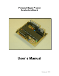
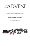
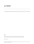
1
User Guide
For the IR-remote controlled audio volume and channel input selector.
This document describes the dual-microcontroller design as of November 2006.
See also the corresponding website at: http://jos.vaneijndhoven.net/switchr/design.html
Document version March 19, 2007
1
Characteristics
The described attenuator provides infra-red remote control for audio volume and input
channel selection. Both volume and channel selection is performed through miniature relays.
Six tiny relays implement a stereo 64-step logarithmic attenuator. The combination of relays
with high-quality (small signal) contacts and prime quality resistors provides a top-class audio
volume control, audibly better then conventional potentiometers that employ a sliding contact
over a resistive layer. The chosen sealed relays will maintain their contact quality over an
extremely large time span. A standard setup employs a small front (control) PCB for IRreception, a visual (display) feedback, and an optional manual switch control, and one relay
PCB that performs the actual audio handling. This relay PCB provides relays for a 2-channel
(stereo) volume control and input channel selection. Multiple of these PCBs can be tied to a
single front control module: 2 prints can be used for balanced (symmetrical) audio systems, 3
prints for 5.1 surround systems, or 4 prints for 7.1 systems.
Traditional potentiometer usage provides a constant input resistance, and variable output
resistance. The switched-attenuator in this design in principle works the other way around: it
has variable input resistance and constant output resistance. (However, due a specific
design trick, the default attenuator resistor values provides a lower output resistance for the
lower half of the volume steps.) You could use this attenuator as a complete passive preamplifier. It depends upon your power amplifier whether the relatively high output resistance
is OK for your system. In general, tube amplifiers feature a high input resistance, and might
do fine. Otherwise, you can actively buffer the output signal of the attenuator, and/or create
your own integrated amplifier with this PCB. In general, I would hesitate a little to drive interchassis audio cables from just this passive attenuator.
The device has volume levels from 00 up to and including 64. Volume levels 01 to 64 span a
dynamic range of 69dB with 63 steps of 1.1 dB. Volume level 00 really disables the input
signals giving zero output.
The default resistor set that I apply, is a series of 12 resistors per channel (R21-R32 and
R41-R52), with values of 56K, 33K, 150K, 27K, 15K, 56K, 5K6, 100K, 2K7, 180K, 100K, 1K8.
Normally, this would provide a suitable replacement for a 100K potentiometer. With these
values, the input/output resistance levels and attenuation as function of the volume step
number are as shown in the figures below:
With these resistor values, the output resistance changes from 22K to 1K8 at the 32'nd step.
The curves show the behavior when the attenuator is loaded with an external (amplifier)
resistance of 100K. Unfortunately, the drop in output resistance makes the attenuation of the
32'nd step dependent on this load resistance. An alternative configuration would keep the
2
output resistance constant at 22K all over, and have all attenuation steps independent on the
load resistance. That would be obtained by changing the final two resistor values of the chain
(100K and 1K8) into 1M2 and 22K. Dropping the output resistance for the lower volume
settings was chosen to potentially reduce hum pickup for the low play levels. Note that the
combination of the 22K output resistance and the 100K load resistance leads to a minimum
attenuation (maximum signal level) of -1.7dB. A 0dB pass-through would only be obtained for
an infinitely-high load resistance.
The table below provides an overview of potential resistor values to create the attenuator.
The first row of values is used in the schematic drawings for the “100k input, 22k output”
attenuator. The other rows shows values for a “47k input, 10k output”, and a “22k input, 4.7k
output” attenuator. The attenuations are chosen such that a good match is obtained with
resistor values from the basic E12 series of values. The Dale RN60D resistor set that I
recently tried uses values from the E96 series. In the table I annotated beneath their value
the number that is printed on these resistors (followed by a letter F). (
R21
R41
R22
R42
R23
R43
R24
R44
R25
R45
R26
R46
R27
R47
R28
R48
R29
R49
R30
R50
R31 R32 (R31) (R32)
R51 R52 (R51) (R52)
100K 56k
E12
33k
150k
27k
15k
56k
5.6k
100k
2.7k
180k
100k 1.8k
1.2M
22k
27k
15k
68k
12k
6.8k
27k
2.7k
47k
1.2k
82k
56k
560k
10k
47K
E12
47K 27.4k 14.7k 68.1k 12.1k 6.81k 27.4k 2.74k 47.5k 1.24k 82k
Dale 2742 1472 6812 1212* 6811 2742 2741 4752 1241 8202
22K
E12
12k
6.8k
27k
4.7k
2.7k
10k
1.2k
18k
560
39k
1k
56.2k 1.0k 562k
5622 1001 5623
10k
1002
22k
4.7k
390
270k
*In some sets, an alternative value of 11.8k is used, denoted with 1182.
I would advise to mount the Dale resistors with their value-identification visible upwards, so
that you can easily check later that they are all mounted in the proper position.
This picture is an example of my own test version, showing the mounting positions with
readable values:
Please note (why I included this photo) that this version of the PCB has an error in its white
annotation text: the resistor names/numbers are not appropriate. The resistor values must be
3
mounted in the same left-to-right order as in above table, which is also the left-to-right order
in the schematics.
The Vishay-Beyschlag resistors that I provide for the 100K or 22K attenuator, have a 5-ring
color code, with a final brown ring for their 1% tolerance. The color coding is documented for
instance on http://www.logwell.com/tech/components/1resistor_color_code.html or with a calculator
on http://www.samengstrom.com/nxl/10116/5_band_resistor_color_code_page.en.html.
Building the attenuator
Most of the PCB assembly process hardly needs explanation: the schematics has clear
component types and identifiers. These identifiers are also annotated on the PCB. Some
remarks are probably helpful for the connections towards components outside of the pcb:
1. Power supply
AC power should be applied to the small 2-pin connector. The circuit will operate from
a 6.0 to 7.5 Vac transformer. A pair of a display and a relay PCB together take a
maximum current of 250mA. A relay PCB alone takes a maximum of 185mA. You can
check that the DC voltage on C1 is between 6.5Vdc and 10Vdc. Higher voltages
might cause the LM2940 to get warm. I typically use a rather small clip-on heatsink. If
you connect the attenuator to a 6.3Vac of your tube amplifier transformer, you will like
to avoid any risc that this rectifier back-fires dirty effects into your precious tube
amplifier transformer. Schottky-type diodes are applied in stead of basic rectifier
diodes, since schottky diodes do not generate ‘recovery’ spikes. To further eliminate
such effects a 470nF capacitor was added to filter the AC voltage. Clearly, the
schottky diodes and low-drop regulator together enable operation from the low 6Vac.
2. Rotary switch
Connecting a rotary switch for manual volume control and channel selection is
optional, the circuit can be used fine from a IR-remote only. The applied type of
switch is a ‘rotary pulse generator’ which can be turned around and around without
mechanical blocking. It uses 3 connections: one common pin connected to ground,
and 2 signal pins, denoted ‘Vol a’ and ‘Vol b’ in the schematics. The microcontroller
has a weak pull-up on these two signals. So if the switch is not connected you should
measure +5V on these. The switch will -in steady state- leave either both pins open
(at 5V) or short both to GND (0V). When the switch is in transition, one of the pins will
precede the other in its transition. The rotation direction is derived from this transition
order. Currently, I use a print-mount version of this switch, alternatively a frontmounted version is also available. The front-mount version does not fit my PCB
(needing a few wires between its contacts and the PCB), but it does have an M7 wire
and screw for front-plate mounting. Note that these switches also have a built-in push
button function, by pressing their shaft. Therefor, a separate 'channel select button'
as described in the following paragraph is not required.
Print mount version of the rotary switch (default).
4
Front-mount version of the rotary switch (upon request).
3. Channel select button
For manual channel (input) selection, a push-button can be optionally connected
between the 2 pins marked with 'push button' on the display PCB. Every press-andrelease will move to the next input channel, with wrap-around at 4 (by default).
4. Power switch output
The relays PCB allows to optionally connect a power-switch relay to switch on/off
other equipment from your IR remote. Obviously, this function only works if the power
of the attenuator itself remains on. Power-switching is triggered by a dedicated button
on your remote control, or by keeping the rotary switch pressed-down for about 2
seconds. When switched to the ‘off’ state, pin 5 on the programming header (‘PGC’)
will be 0V, otherwise it will be +5V (active high). Note that you cannot directly
connect a heavy power-relay between this PGC pin and the digital ground (pin 3 on
this connector), due to the 5V and 25mA current limitation of the microcontroller. (The
Omron G6K seems the ONLY 5V relay with at least 200 ohm coil resistance.)
Power relay
Opto-coupler, or
solid-state relay
Small-signal
relay (G6K)
1K
PGC
150
PGC
PGC
Some circuit options to drive an (external) power-switch relay.
5. Connecting the display PCB with the relay PCB(s)
The display PCB must be connected to the relay PCB. Each PCB has a 5-pin
connector, and I normally will provide a connector set for this. Connecting a pair of
PCBs through these 5 wires works fine. The 5-pin connection is also used (by me) to
download the firmware into the PIC microcontrollers. For normal operation however,
only the middle three pins are actually needed. For symmetric (balanced) audio or
multi-channel audio set-ups, see the description in the next section.
6. Grounding
The PCB (-duo) implements three electronic circuit sections that are electrically totally
isolated from each other: a) The digital control circuit with the microcontrollers, the
power supply, the display and the relay coils, b) left audio resistors and relay
contacts, c) right audio resistors and relay contacts.
Each of these three circuits has its own ground, respectively GND, LGND, RGND.
Because the PCB doesn't tie these together, you can still choose/apply your own
grounding policy as to whether and where to connect these grounds. However, a
5
totally unconnected digital ground seems to induce hum and interference in the audio
part of the attenuator. For typical usage, I would recommend to tie together all your
ground signals (power and signal). The new (Nov. '06) version of the PCB supports
this by soldering two small wires in the locations R1 and R2. Maybe there are a few
special cases, such as with totally separated monoblock amplifiers, where you might
choose to keep LGND and RGND separated. Some of you might also prefer not to
use wire bridges but couple the grounds through small resistors, e.g. 100Ω.
Multi-channel set-up
The design does support symmetric (balanced) audio or multi-channel (5.1 or 7.1) surround
audio. The extra audio channels are handled by connecting extra relay boards to the same
front display board. Multiple relay boards connect to one display board in the following way:
– Each relay board connects to the 6V-7.5V AC power. The new PCBs (of Nov. 06) provide
an 'AC-out' pair of pins for daisy-chain wiring.
– One relay board connects with (at least) the 3 center pins of the 5-pin connector to the
display board. Connecting the left-most and right-most pins is optional but has no
function. (These pins are primarily added for programming the PIC micro-controller.)
– All relay boards connect their GND and PGD, located at pins 3 and 4 of the 5-pin
connector. The new PCBs provide 2 extra output pins for these signals for daisy-chain
wiring. The drawing below shows this set-up for a 2-board symmetric audio configuration.
in1
+ -
in2
+ -
in3
+ -
in4
+ -
out
+ -
in1
+ -
Left audio
in2
+ -
in3
+ -
in4
+ -
out
+ -
Right audio
Vac
GND
+5V
To optional
power relay
data
If you want to mount two relais boards closely above each other, you might want to mount
the capacitor C1 lying flat on the PCB, instead of standing upright. Accordingly, you can bend
the LM2940 horizontally, pointing outside.
In special applications, it might be nice to operate the attenuator relay PCBs further away
from the display PCB, in particular integrating a relay PCB inside each monoblock amplifier.
In that situation, only the data signal (pin 4) and the digital GND (pin 3) needs to be
distributed, and the display PCB can take its 5V supply from a local source. It is for such a
configuration, that each relay PCB has its own 'power down' output signal. A series resistor
6
of 220ohm is recommended in the data signal between the display PCB and off-case
connectors to improve safety and damping.
7
Remote controller compatibility
First thing to do, is find your own remote control handheld that transmits IR signals in a
format that is understood by the device. In practice there exist many different formats, some
of which are shared by multiple companies/brands. Clearly, within each format, many
different codes are used related with activating different functions on different devices. As of
yet, my volume controller understands the widely used Philips RC5 and RC6 formats. All
generic (multi-brand) IR remotes can send these formats. Personally I am using an old
'hauppage' remote. The formats used in modern Sony remotes are not yet supported, they
might be in a future version of the firmware.
If you power-up the attenuator (the display PCB), and everything works correctly, the display
shows ‘P .’ for about 5 seconds, then show ‘ 1.’ for about 1 second, and then reverts
back to showing just ‘ .’. The small dot is merely a ‘power-on’ indicator. The P indicates
that the device is in a mode susceptible to programming. The 1 indicates that audio input
channel 1 is currently selected.
When sending a IR signal to the device three reactions are possible:
• ‘--.’ This indicates that the device cannot handle the format of the received IR
signal. You have to find yourself a different remote (or, for a multi-brand remote,
experiment with a different mode). This error signal is only displayed during the short
power-up programming mode.
• ‘ 3.’ Some one- or two-digit numeric result means that the device performs a proper
reaction on an understood button.
• ‘ .’ No reaction whatsoever. This indicates that the device doesn't know what to do
with the received IR signal. Your remote might be compatible, but the volume
controller has no action associated with this particular button code. This would be the
expected result for a new (still unconfigured) attenuator.
8
Configuring your attenuator
With a compatible IR-remote you can proceed with learning your attenuator to react properly
on your favourite buttons. You (again) power-up the device, obtaining ‘P .’ on its display,
which indicates susceptibility for programming.
a. Within these 5 seconds or so after power-up, you press some button on your remote
that you do NOT want to configure in the selector, and was NOT configured earlier,
such as ‘menu’, ‘OK’, or ‘FastForward’. Assume -for this text- that this button is ‘OK’.
The selector reacts with ‘P1.’ on its display.
b. You can freely press ‘OK’ repeatedly, thereby cycling through ‘P1.’, ‘P2.’, … ‘P9.’,
‘P1.’… If you do not press anything for about 5 seconds, the display will go back to
‘ .’, indicating that you left configuration mode.
c. If the display shows ‘P1.’, and you press any button other than ‘OK’, that button
code is stored in non-volatile memory and will be used later for ‘Volume Up’. The
display reacts with ‘ 1.’ to confirm the coding of function 1. Pressing ‘OK’ again will
move you to a next button to configure.
With repeating steps b. and c. (and/or a.), you can configure the following button codes:
‘P1.’ Volume Up
‘P2.’ Volume Down
‘P3.’ Mute on/off
‘P4.’ Input channel Up
‘P5.’ Input channel Down
‘P6.’ Input channel select numeric 1
‘P7.’ Input channel select numeric 4 (maximum channel number)
‘P8.’ Power-down
‘P9.’ Display mode
The numeric keypad on your remote can be used to select the audio input channel. For this
purpose, the signals of the first button '1' and the last button '4' are to be programmed. As
exception, you could program a different number of input channels, by choosing another
value then '4'. A maximum up to 7 can be used by connecting extra relays outside the
provided PCB: three additional relays can be controlled through the 'aux' signals indicated on
the schematics and on the PCB.
The 'power down' button causes the PGC signal (pin 5 of the 5-pin connector) to value 0. In
power-down mode the attenuator does not react on volume up/down or mute commands.
The power-down mode is left (PGC gets raised) upon a channel-select command.
P9 is not meant to get attenuator reaction upon an extra button, but merely changes the
attenuator mode of display operation. In its default mode, the attenuator shows on its display
a reaction on the last command, by showing the newly selected input channel or the newly
selected volume level for about a second. After a second, the display will return idle (black)
again. If the P9 location is programmed with the same key as 'power-down', then the
attenuator display will show channel selections for a second, but then keep showing the
audio volume level. Only in power-down mode it will make its display idle (black).
9
Ready to use
Waiting a few seconds (or pressing a recognised command code) will exit the program mode
and enter normal use mode. Sending a command will cause the resulting new volume or
input channel to be shown on the display for a few seconds. After that, the display will revert
to its default ‘
.’ (or, if P9 was programmed, the volume setting will be retained). Volume
levels range from ‘00.’ to ‘64.’. Input channels range from ‘ 1.’ to ‘ 4.’. (or, if
programmed through P7, a different upper limit). Channel select up/down has cyclic wraparound. The 'mute' command both mutes and unmutes, volume changes also unmute. The
'power down' command does not also (symmetrically) power-up, mainly because holding
such a key pressed on a remote would cause undesirably quick power on/off cycles. The
power-up is automatically induced by input channel selection.
The attenuator display PCB stores its last used volume and channel selection in non-volatile
(EPROM) memory. At its next power-up it reads those settings to start-up in its previous
state.
One last warning: For its audio signals, the attenuator is truly passive. Its maximum output
resistance is not higher then that of a normal potentiometer, but it retains its high resistance
across a much wider volume range. Some power amplifiers do not like to be driven by such
resistance, or in some system set-ups extra humming might be picked up. Please verify in
your own system that an output resistance of about 10Kohm (for my default 47K Dale
resistor choice) does not cause you any problems. If 10K is problematic, the attenuator
needs to be followed by a driver stage to lower its output resistance. (For which I am
developing a rather nice option...)
Of course, choosing other resistor values can also give you a lower output resistance at the
cost of a lowered attenuator input resistance.
10
Layout and sizes
Sizes are in millimeters.
Screw holes are 3.2mm diameter, they are centered on a 50-mil raster.
The height of the components above the relay/resistor print is typically 22 mm. If you really
must push this, you can reduce this height to about 11 mm. The height of the components
above the display PCB surface is 7mm, which is the height of the 7-segment displays itself.
Happy listening,
Jos van Eijndhoven
March 2007
11