1
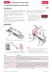
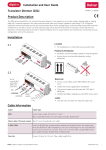
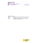
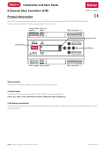
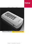
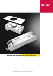
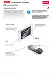
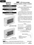
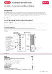
Installation and User Guide
Single-Channel Leading Edge Dimmer (416S and 425S)
The DIGIDIM 416S (16 Amp) and 425S (25 Amp) are wall‑mounted single-channel leading edge (thyristor) dimmers.
Both units also include a 16 A relay circuit.
Controllable by S-DIM, DMX, and Analogue, and fully DALI‑compatible for use as Load Interface Units in a DIGIDIM lighting
control system, the 416S and 425S can also function as stand-alone dimmers.
They can be connected to mains voltage lamps directly, or to low voltage lamps via a wire-wound transformer, and have a
selectable, integral DALI power supply.
1. Remove cover and knockouts
Unscrew screws A, B, C and D.
A
Remove the cover.
B
D
C
Remove the knockouts as required.
Knockouts: top (for control cables)
Knockouts: back
136
67
28
185
21
Ø
274
187
20
20
20
20
Ø
Ø
Ø
Knockouts: base (for power and output cables)
Ø
Ø
Ø
118
Ø
28
30
Ø
20
20
25
20
71
21
165
5
200
71
118
165
200
1
20
67
136
Ø
3.
2.
20
1.
Helvar 416S / 425S Single-Channel Leading Edge Dimmer: Installation and User Guide
2. Mount to Wall
Mounting, Environmental and Clearance Requirements
Mounting
•
•
•
•
Mount the chassis vertically on a flat surface.
Use screws with a head diameter between 7 mm and 9 mm.
Use wall plugs if necessary.
Mount chassis on wall using 4 screws.
Environment
•
•
•
•
The ambient temperature must be between 0ºC and 40ºC.
Air humidity must be between 0% and 90% (non-condensing).
The area must be adequately ventilated.
Do NOT install this product in a damp location.
Clearance
• Ensure enough space is left for ventilation: at 50 mm on each side of the unit. Refer to the mounting dimensions and
clearance diagrams below.
• Leave sufficient clearance to allow cables and trunking to be connected.
• The grilles must NOT be obstructed.
Mounting dimensions and clearance (mm)
50
R3
14
50
R4.5
274
187
50
50
185
200
Helvar 416S / 425S Single-Channel Leading Edge Dimmer: Installation and User Guide
2
3. Electrical Installation
WARNING:
BEFORE COMMENCING ANY ELECTRICAL WORK, ISOLATE THE
ELECTRICITY SUPPLY AT THE MAIN DISTRIBUTION BOARD.
Connections
With the cover removed, connect the earth, mains power, and the control wiring (see details below)
One removable DALI
connector block is
supplied with the
416S/425S
Control
inputs
TERM
B
0V
A
SC
C0
C1
C2
0V
OVR
DA-
SC
DA+
Override DALI
(powered:
83 mA)
Analogue
(0-10 V;
1-10 V)
S-DIM;
DMX
DA
SC
DA
DALI
(non-powered)
RELAY
OUTPUT
Mains
Supply
Input
DIMMER
OUTPUT
AC
L
N
N
L
N
E
SWL
Load
Outputs
DIM
L
N
E
Cable access
Use the knock-outs for cable access. The gap between the back of the case and the wall may be used for cable entry.
Helvar 416S / 425S Single-Channel Leading Edge Dimmer: Installation and User Guide
3
Mains Supply Input
L
N
N
SWL DIM
WARNING: THE SUPPLY INPUT EARTH MUST BE CONNECTED.
Load outputs
Dimmer output
L
N
N
Relay output (Switched load)
L
SWL DIM
N
N
SWL DIM
Control inputs
Control input connection terminals are screw terminals. These control inputs can be connected to the 416S/425S:
DALI (non-powered)
Powered DALI (83 mA)
Analogue signal
S-DIM
DMX
}
Connect only one of these control inputs to the 416S/425S at one time.
The Override input can be connected in addition to any of the other inputs.
If the Powered DALI (83 mA) connection is used, the override input must be treated as
potentially live.
Override
DALI
One DALI connector block is supplied with the 416S/425S.
Connect DALI wires to the connector block, and then attach the block to one of the DALI terminals (powered or non-powered).
Powered DALI:
TERM
B
0V
A
SC
C0
C1
C2
0V
OVR
DA-
SC
DA+
DA
SC
DA
If the built-in 83 mA DALI power supply is required, use the powered DALI connection.
The powered DALI connection is not isolated from the other control outputs.
DA-
SC
DA+
To enable the DALI power connection:
Tighten ALL terminal screws (this internally links the terminal poles).
Ensure correct polarity of DA- and DA+.
DA-:
DALI SC:Screen
DA+: DALI +
Non-powered DALI:
TERM
B
0V
A
SC
If adding another supply to the DALI network, remember that
you must not exceed the DALI power supply limit of 250 mA.
C0
C1
C2
0V
OVR
DA-
SC
DA+
If the DALI network has an adequate power supply, use the non-powered DALI connection.
The non-powered DALI connection is isolated from the other control outputs.
DA
SC
DA
DA:DALI
SC:Screen
DA:DALI
4
Helvar 416S / 425S Single-Channel Leading Edge Dimmer: Installation and User Guide
DA
SC
DA
S-DIM / DMX
TERM
B
0V
A
SC
C0
C1
C2
0V
OVR
DA-
SC
DA+
DA
SC
DA
S-DIM/DMX termination
i
i
ii
TERM
B
SC
0V
A
C0
C1
C2
0V
TERM
i = S-DIM or DMX Data Cable (from previous device)
ii= S-DIM or DMX Data Cable (to next device)
iii= Link for Termination (if unit is at end of S-DIM/DMX cable line)
TERM
ANALOGUE:
B
0V
A
SC
C0
C1
iii
OVR
C2
0V
B
SC
0V
A
C0
C1
C2
0V
OVR
Note: Keep unscreened wire lengths to a minimum
OVR
DA-
SC
DA+
DA
SC
DA
Typical analogue control circuits are shown below. One input only (0 - 10 V or 1 - 10 V) can be used at one time.
0 - 10 V (source)
1 - 10 V (sink)
0 - 10 V
INPUT
0V
C0
0V
10 V
C1
OVERRIDE:
1 - 10 V
C0
C2
TERM
B
0V
A
SC
C0
C1
C2
0V
C1
C2
OVR
DA-
SC
DA+
DA
SC
DA
If the override input connection is short-circuited, e.g. by contact closure on an alarm system, the dimmer is set to its override
level, regardless of external control signals.
0V
5
OVR
Vin < 1.5 V
Ishort= 1 mA
To provide output level override functionality, wire a switch between the ‘0 V’
and ‘OVR’ terminals.
Switch closure sets the light output of the dimmer channel to the override
level.
The override level can be set using the interface (see section 5: The
416S/425S Menu) or Designer software.
If the Powered DALI (83 mA) connection is used, the override input must be
treated as potentially live.
Helvar 416S / 425S Single-Channel Leading Edge Dimmer: Installation and User Guide
4: Power Up
During power up, the following sequence is displayed on the LED Control Panel.
Start-up Sequence:
1. All segments on
2. Product model
(416 or 425)
0.5 sec
5.
3. Software version
0.5 sec
4. Normal Operation
(Status Display)
0.5 sec
The 416S/425S Status Display (default display)
The Status display is the default view during operation.
S-DIM/DMX activity or
Analogue input mode
Power
indicator
The Status display shows:
- the relay (switched) level (left digit)
- the dimmer level (right digit)
- power and input / output indicators
You can view and directly adjust the relay and
dimmed outputs from the status display.
Use the two push buttons (below the the display) to
navigate the features menu and change parameters.
If neither of the buttons is pressed for 10 seconds,
the Status display is shown.
Relay
output
level
Dimmer
channel
output level
Powered
DALI
connection
indicator
Key and LED Descriptions:
Relay (Switched)
This shows the following digits: 0 (0-9%), 1 (10-19%), 2 (20-29%), 3 (30-39%), 4 (40-49%), 5 (50-59%), 6 (60-69%), 7 (70-79%),
8 (80-89%), 9 (9-99%) and F (Full: 100%).
Dimmer channel level
This shows the following digits: 0 (0-9%), 1 (10-19%), 2 (20-29%), 3 (30-39%), 4 (40-49%), 5 (50-59%), 6 (60-69%), 7 (70-79%),
8 (80-89%), 9 (9-99%) and F (Full: 100%).
Power indicator
The power indicator (top segment of the middle digit) is always on when the 416S/425S is powered up.
S-DIM / DMX activity indicator
The S-DIM / DMX activity indicator (centre segment of the middle digit) is normally off, and flashes on intermittently to indicate
S-DIM / DMX activity (communications).
Analogue
The centre segment of the middle digit flashes when Analogue mode is selected.
Software override indicator
The decimal point on the left is illuminated to indicate software override from the override test menu.
DALI power / activity indicator
The DALI indicator (bottom segment of the middle digit) is off if there is no DALI power, and on if DALI power is present. If any
DALI activity is directed to a channel within the device, the indicator blinks off.
Hardware (wired) override indicator
The side segments of the middle digit flash to indicate wired override.
6
Helvar 416S / 425S Single-Channel Leading Edge Dimmer: Installation and User Guide
5: The 416S/425S Menu
How to navigate the menu and configure the 416S/425S
Go to the next item in the main menu
Press and hold both buttons to step through the main menu options.
Select a menu option (access a submenu);
Select the next item in a submenu
When you have navigated to the main menu option you want,
press (and release) either of the buttons to access the submenu.
To step through the submenu items, press (and release) either of the buttons.
Adjust a value / parameter (from submenu);
Adjust a value / parameter (from main menu)
+
-
When you have selected an item in the submenu, to adjust that setting, press and hold one of the buttons.
The currently stored setting will show in non-flashing digits.
Options or values shown in flashing digits are not yet confirmed.
To confirm the new value / parameter, press and hold both buttons.
When you are in the main menu, to adjust the last viewed setting in a main menu option, press and hold one
of the buttons.
Confirm (save) a setting
When you have adjusted a setting, press and hold both buttons to confirm the change (save the change to
system memory)
Return to Status Display (default display)
If no button is pressed for 10 seconds, the Status Display is shown.
The Status Display shown here indicates that the Relay (switched) level is zero, and the level is zero.
Examples of adjusting settings
View and change switched and dimmer levels
1
3
5
6
... [10 s] ...
2
4
+
-
With the status display (1) showing, press either button once (2) to display REl or Chl (3). Press and hold the top or bottom button (4) to adjust the level.
When the required level is reached (5: this example shows 46%), release the button.
After 10 seconds, the Status display is shown (6). The digit 4 indicates 40-49%.
Set S-DIM or DMX address of the dimmer channel
When using S-DIM or DMX control, you can set a specific address for the relay (switched), dimmer, or both. The default address is 1.
1
3
2
5
4
7
6
+
9
8
-
With the status display (1) showing, press and hold both buttons (2) to step through the menu.
When the display shows AdS (3), press the top button once (4) to display Chl.
When Chl is shown (5), press and hold one of the buttons (6) until the required address value is shown (7: this example is 32).
Press both buttons (8) to store the setting. The display flashes 888 when the value is stored (9).
Note 1: When the dimmed and relay channels are separated (ChP = SEP: see Channel Pairing in Menu Options), the base address option can be
used to set both channel addresses at the same time.
Note 2: For DMX control input, enable DMX. For S-DIM control input, disable DMX. See Enable / Disable DMX in Menu Options.
7
Helvar 416S / 425S Single-Channel Leading Edge Dimmer: Installation and User Guide
Menu options
Navigate through the 416S/425S menus using the push buttons located below the display.
Main menu Submenu
Options
Press and hold
both buttons to
step through
Press and hold top/bottom
button to alter / select.
Press (and release) top /bottom
button to enter and step through
submenu
Notes
Status display
Levels
Left: Relay
Right: Dimmer
0: 0-9%;
1: 10-19%
2: 20-29%)
3: 30-39%
4: 40-49%
5: 50-59%
Set the output levels of the relay (switched) output [REl],
Dimmer output [Chl], or both [ALL: available only when
channels are not paired].
6: 60-69%
7: 70-79%
8: 80-89%
9: 9-99%
F: 100%
(Full)
Output levels:
Left digit: Relay (switched) output
Right digit: Dimmer
S-DIM or DMX Address
S-DIM
1 – 254; Disabled (Default: 1)
S-DIM base: 1 – 253
DMX
1 - 512; Disabled (Default: 1)
DMX base: 1 - 511
Set the S-DIM or DMX address of the relay (switched) output
[REl], Dimmer output [Chl], or S-DIM / DMX base address
[bAS].
The base address option is available only when channels are
not paired (ChP = SEP).
DALI Address:
1 – 64;
--- (=Removed);
diS (=Disabled)
Set the DALI address of the relay (switched) output [REl],
Dimmer output [Chl], or DALI base address [bAS].
The base address option is available only when channels are
not paired (ChP = SEP).
If DALI status is --- (Removed), the next time you connect
it to a controller program or router, the DALI address will be
re‑allocated. If DALI status is diS (disabled) the address will
not be re‑allocated.
DALI Address
DALI Base:
1 – 63 (Default: 1);
DMX (Enable / Disable)
Off;
On
Disable [Off] or enable [On] the DMX control input.
For DMX control input, enable DMX.
For S-DIM control input, disable DMX.
Off;
0.10;
1.10
Disable [Off] or enable Analogue control input:
0 - 10 V : source
1 - 10 V : sink
Analogue
Output type (dimmed output)
Output
Output type
Control Protocol
Notes on output types:
t0
Non Dim
All
t1
Linear
S-DIM / DMX
Under S-DIM/DMX control, default
is t 1
t2
Square
S-DIM / DMX
t3
S-law
S-DIM / DMX
t4
DALI logarithmic
DALI
t5
DALI SSL
DALI
t6
DALI linear
DALI
t7
Analogue
Analogue
Under DALI control, default is t 4
Under Analogue control, default is t 7
Minimum fade time
1.00; 0.50; 0.15; 0.02 s
(Default: 1.00 s)
Select the minimum fade time for the relay (switched) output
[REl], Dimmer output [Chl] individually, or both channels (ALL).
P-1 (Paired)
SEP (Separate = non-paired)
Unpair the the relay (switched) output and dimmer output, so
that they are adjusted separately (SEP), or pair them (P-1).
Channel pairing
8
Helvar 416S / 425S Single-Channel Leading Edge Dimmer: Installation and User Guide
Override level
0 – 100; --- (=not set)
Set override level for the relay (switched) output [REl], Dimmer
output [Chl] individually, or both (ALL).
If the override input connection is short-circuited, e.g. by
contact closure on an alarm system, the relay and dimmer
outputs are set to their override level, regardless of external
control signals.
Off;
On
Test the override mode [On] or deactivate override test [Off].
When the override test is running, the relay and dimmer
outputs are set to their override level, regardless of external
control signals, and the side segments of the central digit of
the Status display will flash.
0.1; 1 – 100%.
Set the minimum DALI lighting level for the relay (switched)
output [REl], Dimmer output [Chl] individually, or both (ALL).
Minimum DALI lighting level is the minimum level achieved when
the load is turned on, no matter what scene is called or level is set.
For example, if you set a minimum level of 50% and call scene
4 (at 25% level), the channel output level will be 50%.
S-DIM
2 – 64%
DMX
0.1; 1 – 64%
[P-1 =Channels paired]
Set the switch-on level for the relay (switched) output [REl],
Dimmer output [Chl] individually, or for both (ALL).
The switched load or dimmed load (or both) will not turn on
unless it receives a command to go to or above this level.
1 – 100%.
Default: 100%
Limit the maximum output level of the relay (switched) output
[REl], Dimmer output [Chl] individually, or both (ALL).
Override test
DALI minimum level (DALI mode only)
Switch-on level (S-DIM / DMX mode only)
Maximum load level
Hysteresis
This setting affects the level at which the the relay (switched)
output [REl], dimmer output [Chl], or for both (ALL) turn off.
When hysteresis is on, the switch-off level is 80% of the
switch-on level. At or below the switch-off level, the channel
will be off.
By default:
- When hysteresis is on and the signal rises to 2%, the load
turns on; when it falls to 0%, the load turns off.
- When hysteresis is off (default setting) and the signal rises to
2%, the load turns on; when it falls to 1%, the load turns off.
SCR drive mode
Certain loads may need a different dimming method:
tri: triac mode
Scr: SCR mode
Hyb: Hybrid mode (default)
Reset to defaults
To reset the 416S/425S to the original settings (defaults),
press and hold one of the buttons for 10 seconds.
Restoring factory settings returns all connected lighting to
default levels immediately.
9
Helvar 416S / 425S Single-Channel Leading Edge Dimmer: Installation and User Guide
Technical Data
Power and Protection
Power consumption:
1.3 W (with no output load)
Heat dissipation:
416S: 39 W with maximum load (resistive); 425S: 67 W with maximum load (resistive)
External protection
The mains supply input must be externally protected by an MCB or fuse of a suitable rating.
416S: 16 A Type C MCB maximum. 425S: 25 A Type C MCB maximum.
Thermal protection:
Control board – resettable fuse
Power devices – thermal sensing
Mains supply input
Connections (L, N, E):
Solid: ≥ 6 mm² ; Stranded: ≥ 4 mm²
Terminal type:
Screw terminals
Mains supply voltage:
85 VAC to 264 VAC, 45 - 65 Hz
Cable strip length:
8 mm
Control inputs
DALI
Connections:
1x DALI (standard, non-powered);
1x DALI powered (83 mA).
2-part DIGIDIM connector with paired screw terminals (one supplied with unit)
Cable type and size:
0.5 mm2 — 1.5 mm2 stranded or solid
Cable strip length:
6 mm
DALI consumption:
2 mA
DALI supply output:
Powered DALI: 83 mA (max), 20 VDC (nominal)
DALI data transfer:
DALI standard IEC62386, with Helvar extensions
S-DIM / DMX inputs
Connections:
S-DIM and DMX use the same input connections
Terminal type:
Screw terminals
Cable type and size:
0.22 mm² — 1.5 mm² ; low-loss RS485 Type (multi-stranded, twisted and shielded).
One twisted pair for A and B (85 Ω to 100 Ω impedance), one core or twisted pair for 0 V, and
shield for screen. Example cable: Belden 8102 or Alpha 6222C
Cable strip length:
6 mm
Maximum cable length:
1000 m (low-loss cable)
S-DIM data transfer:
Helvar protocol (RS485, 115 kbps)
DMX data transfer:
DMX512-A protocol
Analogue input
Terminal type:
Screw terminals
Cable type and size:
2-wire; 0.22 mm2 — 1.5 mm2 (screened and twisted)
Maximum cable length:
50 m
Override input
10
Terminal type:
Screw terminals
Cable type and size:
2-wire; 0.22 mm2 — 1.5 mm2 (screened and twisted)
Cable strip length:
6 mm
Maximum cable length:
50 m
Voltage and current:
Input voltage: Vin < 1.5 V; Short-circuit current Ishort = 1 mA
Helvar 416S / 425S Single-Channel Leading Edge Dimmer: Installation and User Guide
Load outputs
Dimmed output
Terminal type:
Screw terminals
Cable type and size:
Solid: ≥ 6 mm² ; Stranded: ≥ 4 mm²
Cable strip length:
8 mm
Relay output (Switched load output)
Terminal type:
Screw terminals
Cable type and size:
Solid: ≥ 6 mm² ; Stranded: ≥ 4 mm²
Cable strip length:
8 mm
Load current:
416S: 16 A; 425S: 16 A
Relay contacts:
High inrush
Conformity and Standards
EMC Emission:
EN 61000-6-3
Immunity:
EN 61547
Harmonics:
EN 61000-3-2*
* May be subject to conditional connection for use above 16 A.
Safety:
EN 60950
Isolation:
4 kV
IP rating:
IP 20
Environmental:
Complies with WEEE and RoHS directives
Mechanical Data
Mounting:
Vertical mounted, secured by four ‘keyhole’ slots.
Dimensions:
200 mm (W) x 274 mm (H) x 104 mm (D)
Weight:
416S: 2 kg
425S: 2.6 kg
Housing:
Powder coated steel (grey)
Operating and Storage Conditions
11
Ambient Temperature:
0ºC — +40ºC
Storage Temperature:
-10°C — +70°C
Relative Humidity:
Max 90%, non-condensing
Helvar 416S / 425S Single-Channel Leading Edge Dimmer: Installation and User Guide
www.helvar.com
Data subject to change without notice
Helvar 416S / 425S Single-Channel Leading Edge Dimmer: Installation and User Guide
Doc. 7860279, issue 01
16.11.2012