1
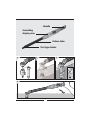
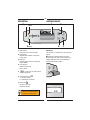
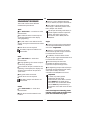
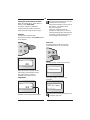
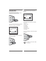
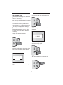
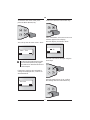
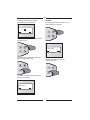
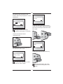
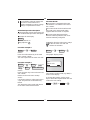
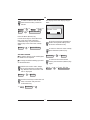
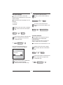
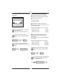
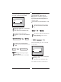
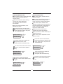
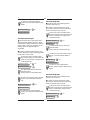
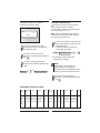
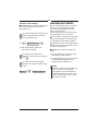
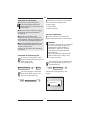
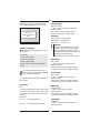
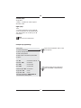
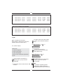
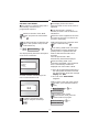
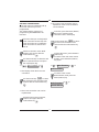
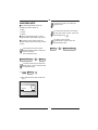
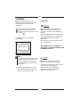
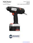
ETORC
Torque & Angle Models
Operating Instructions
Mountz, Inc
ISO 9001 (2000) company
Corporate Headquarters: 1080 North 11th Street, San Jose, CA 95112
www.etorque.com
Phone: (408) 292-2214 Fax: (408) 292-2733
Handle
Swivelling
display area
Carbon tube
Tool type holder
1
2
3
4
A
E- orc
1
1-030
No. 844
N·m
30 - 300 3 lbf·ft
A 22,1 - 221,
GB
SAFETY INFORMATION
These operating instructions provide
important information for the correct
operation of the E-TORC A.
The E-TORC A is a precision tool. Despite
its robust design, the E-TORC A should be
treated like a measuring device.
LIST OF CONTENTS
Do not use the E-TORC A as a striking tool
as this may destroy it.
Safety information. . . . . . . . . . . . . . . . . 2
Before using the E-TORC A, ensure that it
is correctly calibrated. All new E-TORC A
models come with a test certificate in
compliance with DIN ISO 6789.
Intended use . . . . . . . . . . . . . . . . . . . . . 3
Design. . . . . . . . . . . . . . . . . . . . . . . . . . . 3
Technical data . . . . . . . . . . . . . . . . . . . . 3
Please attach only standard sockets and
accessories to the E-TORC A. Do not use
worn or defective accessories and, where
possible, do not use reduction adapters.
Description . . . . . . . . . . . . . . . . . . . . . . . 4
Switching on/off . . . . . . . . . . . . . . . . . . 4
Measurement procedures. . . . . . . . . . . 5
To avoid the danger of slipping, always
attach the E-TORC A onto the screw
connection at a right angle.
Controlled screw tightening . . . . . . . . . 7
Main menu . . . . . . . . . . . . . . . . . . . . . . . 8
Main menu: Setup . . . . . . . . . . . . . . . . . 9
Do not exceed the permitted torque
value for the E-TORC A.
Excessive tightening of the E-TORC A can
cause material failure!
Main menu: Preset Limits. . . . . . . . . . 19
Main menu: Battery. . . . . . . . . . . . . . . 23
Main menu: Memory. . . . . . . . . . . . . . 24
Main menu: Multi-Presets. . . . . . . . . . 26
Main menu: Units . . . . . . . . . . . . . . . . 36
Calibration . . . . . . . . . . . . . . . . . . . . . . 37
2
GB
INTENDED USE
TECHNICAL DATA
The E-TORC A may only be used for its
intended purpose.
Display swivel range
62° clockwise;
62° counter-clockwise
The E-TORC A is designed exclusively
for the controlled tightening of screws.
Zero adjustment
by pressing the button
Any other additional use of the
E-TORC A is not the intended use.
Transducer (Mt)
bending bar with full bridge circuit
Liability will not be accepted for any
damages arising from incorrect use.
Guarantee/warranty services are also
excluded in such cases.
Transducer (DEG)
rate gyroskope
Measurement accuracy over entire
handle length
max. ± 1 % / ±1 Digit
of actual measured value
Resolution
0.1 N·m; DEG: 1°
MODELS
E-TORC A Tool
Model No. cavity
Measurement range
Mt
DEG
Torque display
LCD – graphic display
Weight
8441-010 A 16 Z
10-150 N·m
0°-999°
1400 g
8441-030 A 16 Z
30-300 N·m
0°-999°
1500 g
8443-010 A 9 x 12 mm
10-150 N·m
0°-999°
1400 g
8444-030 A 14 x 18 mm 30-300 N·m
0°-999°
1500 g
Status message
Min and Max values via 3 LED's, acoustic
signal generator and sensory signal
generator (vibration).
Memory
2000 measured values
Power supply
2 batteries 1.5V LR14 or
2 NiH batteries C 1.2V 3500 mAh
Operating life
battery operated:
NiH battery operated:
min.: 50 hours
min.: 24 hours
Temperature range
+10 ° to +40 °C ambient temperature
Interface
RS 232; 300 - 9600 Baud; No parity,
8 data bits, 1 stop bit
3
GB
DESCRIPTION
SWITCHING ON/OFF
4
2(green) 3(red)
5
E- orc A
✓
1(yellow)
1 LED yellow:
Early warning value reached
M
C
R
6
7
Switch on
The E-TORC A is switched on by pressing
key 6.
2 LED green:
Measurement within set preset
limits (OK)
The torque wrench electronics start
functioning and, after a few seconds, the
display will show the current measurement mode of the E-TORC A.
3 LED red:
Measurement outside set preset
limits (NOK)
4 LCD display:
scaled in N•m and
lbf•in / lbf•ft
5
Arrow keys to adjust limit
values (up/down)
✓
M
C
R
✓
6 Confirmation key C
✓: Confirm entry /
C: Calibration mode key
M
7 Menu key R
M: Menu call up /
R: Return (back)
N.m
Track
0,0
This symbol indicates an
action to be implemented
using the E-TORC A keys.
4
GB
MEASUREMENT PROCEDURES
There is a choice between absolute
(N·m) or relative (%) input of limit values.
The E-TORC A offers three different
measurement procedures.
The E-TORC A signals when the limit
value range is reached by means of the
LED's, beeper and vibrator.
Track:
The torque achieved (peak values) is
stored together with the input limit
values, the status of the screw
connection (OK or NOK) and the
date/time.
The Track mode is a "Continuous value
measurement"
This means that the current torque is
continually displayed on the display
during tightening.
The peak value is not retained on the
display during the measurement and after
release.
Angle:
A torque / torque angle measurement
can be implemented without reference
arm in the Angle-Mode.
Limit values are not required.
The LED’s, beeper and vibrator are
deactivated.
However, a start point for the angle
measurement (preset torque) must first
be entered into the wrench.
In addition, the limit values for the
torque / torque angle measurement must
be entered into the wrench.
Peak:
The Peak mode is a "Peak value
measurement".
During tightening, the current torque is
continuously displayed.
Once the start point has been
exceeded, the display shows the
respective torque and angle value.
If a maximum torque is reached or the
tightening is interrupted, the display will
show the last maximum torque value
"peak value".
The tightening torque reached (torque
and angle) and the entered limit values,
status (OK or NOK), the screw
connection and date/time are saved.
Only peak values are stored.
Important!
In order to prevent greater
imprecision during angle
measurement, the E-TORC A must be
held GENTLY in the hand during
each Reset. The confirmation button
should never be pressed during a
movement as this will move the zero
point.
Limit values are not required.
The LED’s, beeper and vibrator are
deactivated.
Preset:
The Preset mode is a "Limit value
measurement".
If this does happen accidentally, please
hold the wrench gently in the hand and
press the confirmation key again.
Limit values must be entered in the
E-TORC A.
5
GB
Setting the measurement procedure:
An angle measurement can only be
carried out once the angle
measurement display can be seen in
the display. This appears after
approx. 3 seconds.
The E-torc needs this time to
activate the angle sensor, which is
normally automatically switched off
for energy-saving reasons during a
normal torque measurement.
When first switched on, the E-TORC A is
always in the Track mode.
In order to switch to a different
measurement procedure, select the
required mode using the arrow keys.
Example:
"Preset limits measurement".
Press the arrow keys until Preset appears
in the display.
Switch off
To switch off the E-TORC A, press the
confirmation key for ca. 3-4 seconds.
✓
M
C
R
✓
M
C
R
N.m
Preset
The display then shows the message:
0,0
Calibration
After selection the display shows
the actually measurement mode!
The angle value is shown in
addition to the torque in the
Angle Mode.
and, after another 2 seconds, the
message:
N.m
ANGLE
0,0
OFF in 2 sec.
000
Please keep pressing the button until
the display goes out.
Indicator of the angle measurement.
6
GB
CONTROLLED
SCREW TIGHTENING
When the input tolerances are reached,
the GREEN LED lights up.
In addition, an acoustic warning signal
can be heard and, depending on the
settings, a sensory signal may be
generated by the vibrator.
Figures 1 – 4
The electronic torque wrench E-TORC A is
suitable for controlled right and lefthanded tightening.
Do not continue tightening after the
signal has been given!
The RED LED lights up if the MAX
tolerance is exceeded, and this is
supported by an acoustic and sensory
warning signal.
1
Attach a rachet head and the matching
socket wrench or other matching accessory
tool (Open-End, Ring, Inbus, Torx®
attachment) for the screw connection.
Depending on the setting of the
E-TORC A, the measured value reached
must either be manually saved to reset
the display to null or it is automatically
saved by the E-TORC A.
The E-TORC A will then be ready for use
immediately.
2
Position the E-TORC A together with the
accessory tool on the screw connection at
right angles.
3
Attention!
To avoid tilting and slipping, always
select the extension that brings the
E-TORC A as close as possible to the
screw connection.
Attention!
The torque transmitted is
dependant on the lever arm length.
Applying the load other than
through to hand grip, or the use of
extension tubes or special
additional tools, renders the
displayed torque value incorrect.
The display area of the E-TORC A can be
swivelled around +/– 62°. This makes it
possible to have the display area
constantly in view while tightening.
4 Operate the E-TORC A by holding it with
1 or 2 hands on the handle only and
tightening uniformly.
In the "Preset" mode, the YELLOW LED
will be the first to signal that the input
tolerances are being approached.
7
GB
MAIN MENU
The following menu items are available:
One detailed example for menu
operation will be explained here and
the rest of the procedures in these
instructions will be given in
abbreviated format.
=> Setup
=> Preset limits
=> Battery State
To reach the main menu, switch on the
wrench and simply press the Menu key.
=> Memory
=> Multi-Presets
=> Units
=> Quit
✓
Once the required menu has been
selected, confirm by pressing the
confirmation key.
M
C
R
The graphic display will switch from the
measurement mode to the main menu.
✓
M
C
R
Setup
OK
< >
An example description is given,
based on the following main menu
"Setup", on how to call up a sub
menu, change settings and return to
the active measurement mode.
The display shows:
Setup
Use the arrow keys to select the
required main menu.
✓
M
C
R
8
GB
MAIN MENU SETUP
The first sub menu will be displayed:
"RS 232".
First switch from the current
measurement mode to the main menu
overview: Press the Menu key.
RS 232
OK
✓
< >
M
C
R
The following sub menus are available:
=> RS 232
=> Date – Time
The main menu overview shows the first
main menu "Setup" on the display.
=> Contrast
=> Language
=> Autoreset
=> Preset Abs-Rel
=> Vibration
Setup
OK
< >
Use the arrow keys to select the required
sub menu.
Confirm the "Setup" display to open the
main menu "Setup".
✓
✓
R
In this example, the sub menu "Date Time" is called up.
M
C
M
C
R
9
GB
Sub menu Date - Time
Normally, these settings are default set
during initial commissioning of the
wrench in the factory.
Even changing the batteries will not affect
these settings.
Confirm this with the confirmation key.
However, there are always
circumstances requiring modification of
date and time (e.g. a different time zone).
✓
To change or display these settings,
proceed as described below:
M
C
R
The currently set time and date will be
displayed.
In the main menu item "Setup", select
the menu item "Date - Time" with the
arrow keys.
Confirm the selection with the
confirmation key.
14:58:23
27.05.03
✓
To leave this display, press the
confirmation key again.
M
C
R
Following confirmation, the menu "View
Date - Time" will appear in the display.
✓
R
To change the time and date, use the
arrow keys to select the menu "Set time".
View Date - Time
OK
M
C
< >
The set time and date can be displayed
here.
✓
10
M
C
R
GB
To leave the sub menu at this point,
press the Menu (Return) key.
Confirm this with the confirmation key.
✓
✓
M
C
R
M
C
R
After confirmation, the time in hours and
minutes appears in the display.
The hour display is marked in black.
This calls up the sub menu "Date - Time".
11 :48
Date - Time
OK
OK
The hour can now be changed using the
arrow keys.
To return to the measurement mode,
press the Menu (Return) key again
and continue as described at the end
of this example.
If the menu "Set time" was selected to
change the displayed time, continue as
described below.
✓
M
C
R
Once the required hour is set, confirm
the settings with the confirmation key.
Set time
OK
< >
< >
< >
✓
11
M
C
R
GB
The black marking now changes
automatically to the minutes.
Set date
To set the date, select the menu "Set
date" with the arrow keys.
11 :48
OK
< >
✓
M
C
R
The minutes can also be changed with
the arrow keys.
Set date
✓
M
C
OK
R
The settings must then be confirmed
with the confirmation key.
✓
Confirm the selection with the
confirmation key.
M
C
R
✓
The menu "Set time" will then appear
again in the display.
Set time
OK
< >
< >
12
M
C
R
GB
The date will then be shown in the
display, with the day displayed on a dark
background.
Setup
OK
< >
27. 05.03
OK
< >
In order to return to the measurement
mode, press the Menu (Return) key again
or use the arrow keys to select the menu
item "Quit".
Changing the date is the same
procedure as described in "Set time".
Confirm the set date with the
confirmation key.
or
M
✓
R
✓
M
C
R
M
C
R
Quit
OK
< >
Press the Return key once to return to
the sub menu "Date - Time".
Confirm this with the confirmation key.
Date - Time
OK
< >
✓
Press the Return key again to return
to the main menu "Setup".
M
C
R
Following confirmation, the active
measurement mode appears in the
display.
13
GB
Sub menu RS 232
The E-TORC A is equipped with an RS
232 interface. It is located on the rear of
the E-TORC A.
It is possible to select all menus and
sub menus as described in the
previous example in order to change
settings or implement functions.
To communicate via the interface with
the E-TORC A, the data transfer cable
supplied with the wrench is required.
Abbreviated procedure description
The remainder of these instructions will
use an abbreviated procedure description.
To ensure that data transmission
functions without problems, both units
must be identically configured.
Example for the display:
Setup
Action / Result: =>
Key depiction:
✓
Switch from the main menu "Setup"
to the sub menu "RS 232" and
confirm the selection.
C
Procedure example 1:
Setup
=>
✓
C
=>
RS 232
Setup
=>
✓
C
=>
RS 232
=>
✓
C
means:
Press the confirmation key in the main
menu "Setup". Result:
This calls up the first sub menu "RS 232".
The graphic display shows:
9600
Procedure example 2:
RS 232
=>
=>
M
R
Quit
=>
Baud rate
Setup
=>
=>
=>
OK
< >
Track 0.0 Nm
means:
Press the menu key in the sub menu "RS
232". Result:
Returns to the main menu "Setup".
The currently set baud rate (e.g. 9600) is
shown in the display.
To change this setting, use the arrow
keys to select the required baud rate and
confirm the new setting.
Action:
Use the arrow keys to select main menu
"Quit" and press the confirmation key.
Result:
This leaves the menu mode and returns
to the active measurement mode.
9600
14
=>
=>
14400
=>
✓
C
GB
The display shows the display "Bright Dark".
In order to return to the current
measurement mode, proceed as
follows.
RS 232
Quit
M
=>
=>
R
✓
=>
=>
C
Setup
=>
=>
Bright - Dark
Track 0.0 Nm
OK
< >
Press the Menu (Return) key.
Use the arrow keys to select the menu
item "Quit" and confirm with the
confirmation key or press the Menu
(Return) key in the menu item "Setup"
again.
Setup
=>
M
R
=>
Press the arrow keys repeatedly to
obtain the required setting. Then
press the confirmation key.
Track 0.0 Nm
To return to the main menu "Setup",
press the Menu (Return) key.
Sub menu Contrast
The graphic display can be made lighter
or darker here as required.
Contrast
Switch to the main menu "Setup"
and confirm with the confirmation
key. Result: The first sub menu "RS
232" is displayed.
=>
✓
C
=>
Setup
RS 232
Use the arrow keys to select the sub
menu "Contrast" and press the
confirmation key.
=>
Contrast
=>
✓
M
R
=>
Setup
To return to the measurement
mode, press the Menu (Return) key
again.
To change the default settings, proceed
as described below.
Setup
=>
C
15
=>
M
R
=>
Track 0.0 Nm
GB
To return to the main menu
"Setup", press the Menu (Return)
key.
Sub menu Language
Use this menu item to select the
required menu language to be used in the
graphic display.
The following menu languages can be
selected:
Language
=>
M
=>
R
Setup
=> German
To return to the measurement
mode, press the Menu (Return) key
again.
=> English
Switch to the main menu "Settings"
and confirm with the confirmation
key.
Setup
=>
✓
C
=>
Setup
=>
R
Track 0.0 Nm
Sub menu Autoreset
The E-TORC A has a function that can
automatically save the displayed
measured value.
After the measured value is saved, the
value is reset to zero in the display.
confirmation key.
Language
=>
✓
This function can be switched on or off.
C
The current language setting, e.g.
"English" is shown in the display.
Switch to the main menu "Setup"
and confirm with the confirmation
key.
Setup
English
OK
M
RS 232
Use the arrow keys to select the sub
menu "Language" and press the
=>
=>
=>
✓
C
=>
RS 232
< >
Use the arrow keys to select the sub
menu "Autoreset" and press the
confirmation key.
Press the arrow keys to obtain the
required language setting.
Then press the confirmation key.
=>
16
Autoreset
=>
✓
C
GB
The current setting, e.g. "Off" is shown in
the display.
Sub menu Preset Abs-Rel settings
This sub menu item can be used to
select the input type for the limit values.
Select between input in
=> absolute values
Off
=> relative values
OK
< >
With absolute (Abs.) input of limit
values, the values must be entered in the
corresponding units.
Example specification 40 N·m ± 10 N·m:
Press the arrow keys to obtain the
required setting.
Then press the confirmation key.
=>
M
R
=>
Setup
=>
M
R
=>
=> Nominal value:
40 N·m.
=> Max. limit value:
50 N·m.
Example: Specification 15.5 N·m ±10%
To return to the measurement
mode, press the Menu (Return) key
again.
Setup
30 N·m.
When entering relative (Rel.) limit
values, the values must be entered in
percent (%).
The E-TORC A then calculates the absolute
limit values.
To return to the main menu
"Setup", press the Menu (Return)
key.
Autoreset
=> Min. limit value:
=> Min. limit value:
13.95 N·m.
=> Nominal value:
15.5 N·m.
=> Max. limit value:
17.05 N·m.
Switch to the main menu "Setup"
and confirm with the confirmation
key.
Track 0.0 Nm
Setup
=>
✓
C
=>
RS 232
Use the arrow keys to select the sub
menu "Preset Abs-Rel" and press
the confirmation key.
=>
17
Preset Abs-Rel
=>
✓
C
GB
The current limit value display setting,
e.g. "Abs." is shown in the display.
Sub menu Vibration
To facilitate work, the E-TORC A is
equipped with a vibration signal. This
indicates that the specified tightening
torque has been reached by means of a
vibrating signal.
Abs.
OK
This function can be switched on or off.
< >
Switch to the main menu "Setup"
and confirm with the confirmation
key.
Press the arrow keys to change the
setting to "Rel.".
Then press the confirmation key.
Setup
To return to the main menu
"Settings", press the Menu (Return)
key.
Preset Abs-Rel
=>
M
R
=>
M
R
=>
C
=>
RS 232
Setup
Vibration
=>
✓
C
The current setting, e.g. "On." is shown
in the display.
To return to the measurement
mode, press the Menu (Return) key
again.
=>
✓
Use the arrow keys to select the sub
menu "Vibration" and press the
confirmation key.
=>
Setup
=>
Track 0.0 Nm
On
OK
< >
Note:
This settings refer only to torque
measurements!
Angle measurements are excluded.
Press the arrow keys to change the
setting to "Off".
Then press the confirmation key.
The vibration function is switched off.
18
GB
MAIN MENU: PRESET LIMITS
To return to the main menu
"Setup", press the Menu (Return)
key.
Vibration
=>
M
R
=>
First switch from the current
measurement mode to the Preset
mode:
Press the arrow keys until Preset
appears in the display.
Setup
To return to the measurement
mode, press the Menu (Return) key
again.
Setup
=>
M
R
=>
Switch from the measurement
mode to the main menu overview:
Press the Menu key.
Track 0.0 Nm
Preset 0.0 Nm
Attention!
The vibrator will be automatically
deactived by the E-TORC A when the
battery voltage has reached a
critical level!
=>
M
R
=>
Setup
Use the arrow keys to select the
main menu "Preset-Limits" and
press the confirmation key.
=>
Preset-Limits
=>
✓
C
The E-TORC A can set the following limit
values for the Preset mode or the Angle
Mode:
=> Nominal value
=> Maximum value
=> Minimum value
=> Notice value
=> Preset torque
=> Angle Min.
=> Angle Max
Note:
The LED's, BUZZER and VIBRATION
SENSOR are only active in the Preset
Mode or the Angle Mode.
They have no function in the
measurement modes Track and Peak.
19
GB
Sub menu Nominal value
The nominal value is greater than the
minimum value and smaller than the
maximum value!
Sub menu Maximum value
The maximum value is greater than
the nominal value!
When the maximum value is reached,
the red LED lights up and the buzzer
sounds.
When the nominal value is reached,
the green LED lights up permanently and
the buzzer sounds.
The input must be either a relative (%)
or absolute (e.g. N·m) value.
The setting is documented.
Input must always be an absolute
value, e.g. in "N·m".
The setting is documented.
In the main menu "Preset Limits",
use the arrow keys to select the sub
menu "Maximum value" and press
the confirmation key.
In the main menu "Preset Limits",
use the arrow keys to select the sub
menu "Nominal Value" and press
the confirmation key.
Preset-Limits
=>
✓
Nominal Value
=>
✓
C
=>
Preset-Limits
=>
✓
Maximum Value
=>
✓
C
Use the arrow keys to select the
required maximum value.
Then press the confirmation key.
To return to the main menu "Preset
Limits", press the Menu (Return)
key.
To return to the main menu "Preset
Limits", press the Menu (Return)
key.
Maximum Value
=>
=>
C
Use the arrow keys to select the
required nominal value.
Then press the confirmation key.
Nominal Value
C
M
R
=>
=>
M
R
=>
Preset-Limits
Preset-Limits
To return to the measurement
mode, press the Menu (Return) key
again.
To return to the measurement
mode, press the Menu (Return) key
again.
Preset-Limits
=>
M
R
Preset-Limits
=>
Preset 0.0 Nm
Preset 0.0 Nm
20
=>
M
R
=>
GB
Sub menu Minimum value
The minimum value is greater than the
notice value and smaller than the
nominal value!
Sub menu Notice value
The notice value is smaller than the
minimum value!
The notice value will warn the user in
time that the tolerance range of the
screw connection is being approached.
When the minimum value setting is
reached, the green LED flashes.
The minimum value reached is
documented!
The notice value is shown in the
display as a peak value. This means that
the value reached will be retained and
shown in the display even after the
wrench has been released.
The input must be relative (%) or
absolute (e.g. N·m)
In the main menu "Preset Limits",
use the arrow keys to select the sub
menu "Minimum Value" and press
the confirmation key.
Preset-Limits
Minimum Value
✓
=>
=>
✓
C
When the notice value limit is
exceeded, the yellow LED flashes.
The input must be either relative (%) or
absolute (e.g. N·m).
=>
The notice value is dependent on the
minimum value.
C
In the main menu "Preset Limits",
use the arrow keys to select the sub
menu "Notice Value" and press the
confirmation key.
Use the arrow keys to select the
required minimum value.
Then press the confirmation key.
Preset-Limits
To return to the main menu "Preset
Limits", press the Menu (Return)
key.
Minimum Value
=>
M
Notice Value
Preset-Limits
=>
M
R
✓
=>
C
To return to the main menu "Preset
Limits", press the Menu (Return)
key.
To return to the measurement
mode, press the Menu (Return) key
again.
Preset-Limits
=>
C
Use the arrow keys to select the
required preset limit.
Then press the confirmation key.
=>
R
✓
=>
Notice Value
=>
Preset-Limits
Preset 0.0 Nm
21
=>
M
R
=>
GB
To return to the measurement
mode, press the Menu (Return) key
again.
Preset-Limits
=>
M
Sub menu Angle Min
The angle min value setting will be
stored in the memory.
In order to set the angle min value,
you need to switch from the measuring
mode to the main menu mode.
=>
R
Preset 0.0 Nm
In the main menu "Preset Limits",
use the arrow keys to select the sub
menu "Angle Min" and press the
confirmation key.
Sub menu Preset Torque
The preset torque is the torque that
determines the starting point for angle
measurement (DEG). This means that an
angle value is shown in degrees on the
display when the preset torque is
exceeded.
Preset-Limits
Angle Min
Preset Torque
=>
✓
✓
Angle Min
=>
C
=>
M
=>
R
Preset-Limits
=>
C
=>
C
To return to the main menu "Preset
Limits", press the Menu (Return)
key.
In the main menu "Preset Limits",
use the arrow keys to select the sub
menu "Preset Torque" and press the
confirmation key.
=>
✓
✓
Use the arrow keys to select the
required value.
Then press the confirmation key.
In order to set the preset torque, you
need to switch from the measuring mode
to the main menu mode.
Preset-Limits
=>
To return to the measurement
mode, press the Menu (Return) key
again.
C
Use the arrow keys to select the
required value.
Then press the confirmation key.
Sub menu Angle Max
The angle max value setting will be
stored in the memory.
To return to the main menu "Preset
Limits", press the Menu (Return)
key.
Preset Torque
=>
M
R
In order to set the angle max value,
you need to switch from the measuring
mode to the main menu mode.
=>
In the main menu "Preset Limits",
use the arrow keys to select the sub
menu "Angle Max" and press the
confirmation key.
Preset-Limits
To return to the measurement
mode, press the Menu (Return) key
again.
Preset-Limits
Angle Max
22
=>
=>
✓
C
✓
C
=>
GB
MAIN MENU: BATTERY
Use the arrow keys to select the
required value.
Then press the confirmation key.
First switch from the current
measurement mode to the main
menu overview:
Press the Menu key.
To return to the main menu "Preset
Limits", press the Menu (Return)
key.
Angle Min
M
=>
R
Preset 0.0 Nm
=>
Preset-Limits
=>
M
R
=>
Setup
Use the arrow keys to select the
main menu "Battery".
To return to the measurement
mode, press the Menu (Return) key
again.
Battery State
=>
TIP: Check values
To check the described preset limits
without changing the current settings,
leave each displayed sub menu by
pressing the menu (Return) key.
Sub menu Battery state
The E-TORC A allows the battery status
to be called up.
The status is displayed in Volts and as
a bar chart (Min – Max).
Example:
To check a set value, use the arrow
keys in the main menu "Preset
Limits" to select the required sub
menu and press the confirmation
key.
Open the main menu "Battery
State" with the confirmation key.
Battery State
Preset-Limits
=>
✓
Maximum Value
=>
✓
C
C
=>
120 Nm
=>
M
R
=>
C
After a few seconds, the display will
indicate the current battery status.
.
Max
Min
2.75v
120 Nm
✓
=>
Leave the display again, without
changing anything, by pressing the
Menu (Return) key.
=>
=>
Maximum Value
.
23
GB
MAIN MENU: MEMORY
To return to the main menu "Battery
State", press the confirmation key
✓ .
The following three sub menus can be
selected in the main menu "Memory":
C
=> View memory
To return to the measurement
mode, press the Menu (Return) key.
Battery State
=>
M
R
=> Print memory
=> Clear memory
First switch from the current
measurement mode to the main menu
overview:
Press the Menu key.
=>
Preset 0.0 Nm
Preset O.0 Nm
Note:
To ensure the longest possible
operating life of the wrench, the
E-TORC A switches itself off
automatically approx. 3 minutes
after its last use.
=>
M
R
=>
Setup
Use the arrow keys to select the
main menu "Memory" and press the
confirmation key.
=>
Memory
=>
✓
C
Sub menu "View memory"
The memory content can be shown
here in the display.
The display shows the memory
location number in the top left and the
measurement value unit in the top right
corner.
The centre of the display shows the
measurement value of the memory
location.
Use the arrow keys to select the sub
menu "View Memory" and press the
confirmation key.
=>
24
View Memory
=>
✓
C
GB
The display shows the content in
memory location No. 0001:
Sub menu "Print memory"
The RS 232 interface can be used to
print out the memory contents.
The E-TORC A can be connected directly
to a serial printer or a PC.
N.m
0001
To prepare a printout of the memory,
switch from the measurement mode to
the main menu "Memory".
15,5
Use the arrow keys to select the sub
menu "Print Memory" and press the
confirmation key.
To start the printout, press the
confirmation key again.
Use the arrow keys to scroll
through the memory and display
the required value.
Print Memory
=>
To return to the main menu
"Memory", press the Menu (Return)
key M .
To return to the measurement
mode, press the Menu (Return) key
again.
=>
M
R
=>
✓
C
✓
=>
C
=> The display briefly shows the
information "printing".
R
Memory
=>
Note:
When relative limit values are
entered, they are converted to
absolute values and displayed on the
memory printout as absolute values.
Preset 0.0 Nm
To return to the main menu
"Memory", press the Menu (Return)
key M .
R
Presentation of memory content:
Mem. Measuring
Min
Max
Angle
Locat. values
Preset
Min Max Status
Time
Date
Totque
Preset
No.
0001
015.5 N·m 010.0 N·m 016.0 N·m
20
10 N·m
15
25
OK
0002
015.0 N·m 012.5 N·m 014.5 N·m
10
5 N·m
5
9
NOK
12:13:00 05.03.2003
2
0003
012.5 N·m 010.0 N·m 013.0 N·m
34
7 N·m
27
39
OK
12:14:00 05.03.2003
1
0004
014.0 N·m 012.7 N·m 016.0 N·m
13
15 N·m
8
15
OK
12:15:00 05.03.2003
3
0005
...............
25
11:55:00 05.03.2003
GB
MAIN MENU: MULTI-PRESETS
Sub menu "Clear memory"
To delete memory content, switch from
the measurement mode to the main
menu "Memory".
A so-called Multi-Preset is a program
in which various tightening options
(max. 25) and their paramters (limit
values) can be stored.
These multi-presets are loaded via the
RS 232 interface into the E-TORC A.
Use the arrow keys to select the sub
menu "Clear Memory" and press
the confirmation key.
Clear Memory
=>
=>
✓
If the E-TORC A is working in the preset
mode, the parameters can be manually
or automatically selected and edited.
The E-TORC A saves all recorded data so
that they can later be transfered to a PC
via the RS 232 interface.
C
=> The display briefly shows the
information "clearing".
There are two options to program a
preset:
1. The programming of a preset using
the supplied “Excel® Macro”
To return to the main menu
"Memory", press the Menu (Return)
key M .
2. Or the programming of a preset using
a normal terminal program (e.g.
Hyperterminal in Windows®)
R
To return to the measurement
mode, press the Menu (Return) key
again.
Memory
=>
M
R
=>
Note:
With both options, the E-TORC A and
the PC must be connected and
configured via the serial interface.
Follow the instructions given in the
section "Main menu: Setup" in the
sub menu "RS 232"!
Preset 0.0 Nm
26
GB
Load preset via “Excel Macro”
Connect the E-TORC A with the PC.
The following sub menus are available
in the main menu "Multi-Presets":
=> Edit Presets
Note the operating instructions
located separately on the CD for the
Excel® Macro.
=> Auto Presets
=> Manual Presets
Open the "Macro" instructions using
the program Microsoft PowerPoint®
from the CD.
Sub menu "Edit Presets"
Use this sub menu to create multipresets and transfer them to the E-TORC A.
If you do not have Microsoft
PowerPoint® on your PC, please start
the Powerpoint Viewer (ppviewer97.exe)
on the CD via your Windows Explorer.
Important:
To create a multi-preset, you will need
a PC with a terminal program (e.g.
Hyperterminal under Windows).
The E-TORC A and the PC must be
connected and configured via the
serial interface.
Follow the instructions given in the
section "Main menu: Setup" in the
sub menu "RS 232"!
Open the preset file required for your
E-TORC A model (844X-0X0 A) from the
CD with a double click.
Continue as described in the operating
instructions.
Load preset via terminal program
To enter the preset mode, switch
from the measurement mode to the
main menu mode:
Press the Menu key.
Preset 0.0 Nm
=>
M
R
=>
Use the arrow keys to select the sub
menu "Edit Presets" and press the
confirmation key.
Use the arrow keys to select the
main menu "Multi-Presets" and
press the confirmation key.
=>
Multi-Presets
=>
✓
Edit Preset
=>
Setup
=>
✓
C
The following note appears in the
display:
C
Connecting
OK
27
< >
GB
Following successful connection, the
following note appears in the display:
Second query:
Nominal value:
=> N·m = Nominal value input in N·m
(or Lbf·ft, etc.)
The values must be input in whole
numbers without comma or point.
E-Torc A
Multi-Preset Edit
Examples:
Mode
Value: 100.0 => Input: 1000
Value: 15.5
=> Input: 155
Value: 7.2
=> Input: 72
Attention!
Different measurement units cannot
be used in one preset (e.g. N·m and
Lbf·ft). In order to measure using a
different measurement unit, select the
required measurement unit
beforehand in the menu item "Units".
Create multi-presets
The following query appears on your
PC monitor:
Select from
1: Load multi-preset
2: Show multi-preset
Third query:
3: Clear multi-preset
Min. value:
=> N·m = minimum value input as
absolute value.
Value input in whole numbers without
comma or point (see examples above).
4: NOK screw connections permitted
q: quit
To create a multi-preset, press "1"
and confirm by pressing the ENTER
key on the PC keyboard.
Fourth query:
Max. value:
=> N·m = maximum value input as
absolute value.
Value input in whole numbers without
comma or point (see examples above).
=> The following queries then appear on
the monitor.
First query:
Fifth query:
Pos:
Preset torque:
=> N·m = start value for angle
measurement.
Value input in whole numbers without
comma or point (see examples above).
=> Specify the position where this screw
connection should be located. (Up to 25
parameter sets can be stored in a multipreset.)
Example:
Pos.: 1
Pos.:14
Sixth query:
=> First preset limit.
Angle Min:
=> DEG ° = Minimum value input as
absolute value.
=> Fourteenth preset limit.
28
GB
Seventh query:
Angle Max:
=> DEG ° = Maximum value input as
absolute value.
Eigth query:
Text:
=> A brief description of the required
screw connection can be entered here.
This description can contain up to 16
characters.
Note:
Spaces are also characters!
Example of programming:
Select from
Input via PC keyboard: 1 for "Load
multi-preset".
1: Load multi-preset
2: Show multi-preset
3: Clear multi-preset
4: NOK screw connections permitted
q: quit 1:
Pos: 01
=> Preset Limit val. 01
Nominal: 130
=> 13 N·m
Min: 115
=> 11.5 N·m
Max: 145
=> 14.5 N·m
Confirm inputs via PC keyboard
with the ENTER or RETURN key.
Preset torque: 90 => 9.0 N·m
Angle Min: 10
=> 10°
Angle Max: 15
=> 15°
Text (16 characters): Seat screw 1L
=> Preset limits description
29
GB
Select from
Input via PC keyboard: 1 for "Load
multi-preset".
1: Load multi-preset
2: Show multi-preset
3: Clear multi-preset
4: NOK screw connections permitted
q: quit 1:
Pos: 02
Nominal: 200
Confirm inputs via PC keyboard
with the ENTER or RETURN key.
Min: 175
Max: 225
Text (16 characters): Seat screw 1R
To leave the macro programming,
enter "q" and confirm with ENTER.
Show multi-preset
Once a multi-preset has been created,
it can be displayed on the PC monitor.
Select from
1: Load multi-preset
Input via PC keyboard: 2 for "Show
multi-preset" and ENTER key.
2: Show multi-preset
3: Clear multi-preset
4: NOK screw connections permitted
q: quit 2:
=> The multi-preset contents will then be
displayed.
NOK screw connection not permitted
Pos
Text
Nominal
MIN
MAX
01
Seat screw 1L
13 N·m
11.5 N·m
14.5 N·m
9.0 N·m
10 DEG
15 DEG
02
Seat screw 1R
20 N·m
17.5 N·m
22.5 N·m
8.0 N·m
15 DEG
20 DEG
03
Seat screw 2L
22 N·m
19.5 N·m
24.5 N·m
5.0 N·m
7 DEG
11 DEG
04
Door chk str.f.L
12 N·m
8.5 N·m
14.5 N·m
9.0 N·m
10 DEG
15 DEG
05
S.belt F.L
120 N·m
117.5 N·m
122.5 N·m
10.0 N·m
25 DEG
31 DEG
06
Belt lock F.L
30 N·m
27.5 N·m
32.5 N·m
9.0 N·m
10 DEG
15 DEG
07
Window l. 1L
10 N·m
7.5 N·m
12.5 N·m
9.0 N·m
10 DEG
15 DEG
08
Window l. 2L
15 N·m
12.5 N·m
17.5 N·m
9.0 N·m
10 DEG
15 DEG
09
.....
30
Preset Torque
Angle: Min
Max
GB
Change multi-preset
If it is necessary to change previously
loaded preset positions, it is possible to
overwrite the corresponding position
using Point 1 "Load multi-preset".
All values of the position preset must be
entered again.
Example: Error in Pos. 01
PC monitor display:
Input via PC keyboard: 1 for "Load
multi-preset" and ENTER key.
Select from
1: Load multi-preset
2: Show multi-preset
3: Clear multi-preset
4: NOK screw connections permitted
q: quit 3:
Pos: 01
Confirm inputs via PC keyboard
with the ENTER or RETURN key.
Nominal: 130
Min: 115
Max: 145
Text (16 characters): Seat screw 1L
=> The old inputs are now overwritten.
Clear multi-presets
PC monitor display:
Attention!
Carrying out this function will delete
all presetted positions.
Select from
1: Load multi-preset
2: Show multi-preset
3: Clear multi-preset
Input via PC keyboard: 3 for "Clear
multi-preset and ENTER key.
4: NOK screw connections permitted
q: quit 3:
31
GB
NOK screw connections permitted
If several limit values have been stored
in the macro, the E-TORC A will load the
next limit value after every OK when in
the macro automatic mode.
If the screw connection is NOK,
the E-TORC A stops at this screw
connection until it is OK.
To allow NOK screw connections,
this function can be used to instruct the
E-TORC A.
PC monitor display:
Select from
1: Load multi-preset
2: Show multi-preset
3: Clear multi-preset
Press key 4 on the PC to change the
selection "NOK screw connections
permitted".
4: NOK screw connections permitted
q: quit 4:
=> The following query appears:
NOK screw connections permitted y/n
Enter a "y" for yes or a "n" for no
and confirm with the ENTER key.
To check the settings, press key 2
on the PC for the selection "Show
multi-preset" and confirm with the
ENTER key.
=> The following screenshot will appear
on the monitor:
32
GB
NOK screw connections permitted
01
Seat screw 1L 13 N·m
11.5 N·m
14.5 N·m
9.0 N·m
10 DEG
15 DEG
02
Seat screw 1R 20 N·m
17.5 N·m
22.5 N·m
8.0 N·m
15 DEG
20 DEG
03
Seat screw 2L 22 N·m
19.5 N·m
24.5 N·m
5.0 N·m
7 DEG
11 DEG
...
....................
................
................
............
or:
NOK screw connection not permitted
01
Seat screw 1L 13 N·m
11.5 N·m
14.5 N·m
9.0 N·m
10 DEG
15 DEG
02
Seat screw 1R 20 N·m
17.5 N·m
22.5 N·m
8.0 N·m
15 DEG
20 DEG
03
Seat screw 2L 22 N·m
19.5 N·m
24.5 N·m
5.0 N·m
7 DEG
11 DEG
...
....................
................
................
............
q: quit
To return to the main menu "MultiPresets", press the Menu (Return)
key.
On completion of the macro
programming, interrupt the connection
between the PC and the E-TORC A.
=>
PC monitor display:
Edit Presets
M
=>
R
=>
Multi-Presets
Select from
To return to the current
measurement mode, press the
Menu (Return) key.
1: Load multi-preset
2: Show multi-preset
3: Clear multi-preset
4: NOK screw connections permitted
Multi-Presets
q: quit
=>
M
R
=>
Preset 0,0 Nm
Disconnect the connection by
pressing the "q" key on the PC
keyboard.
The cable connection between the
E-TORC A and PC can now be
disconnected.
Note:
For questions regarding presets
programming, please contact the
manufacturer Richard Abr. Herder KG.
=> The display of the E-TORC A shows "Edit
Presets".
33
GB
Sub menu "Auto Presets"
If this function is selected, the preset is
automatically executed in the
programmed sequence.
The display shows the current
measured value as soon as the screw is
tightened.
If the preset limit is reached, a
vibration, the LED's and the buzzer will
indicate this.
Switch to the main menu "MultiPreset" and press the confirmation
key ✓ .
After the screw is tightened, the value
and status of the screw connection can
be seen in the display.
C
Confirm the scew connection with
the confirmation key ✓ .
Use the arrow keys to select the sub
menu "Auto presets" and press the
confirmation key.
Auto Presets
=>
=>
✓
C
If the setting "NOK screw connections
not permitted" has been selected, this
preset position is repeated while the
status is NOK until the status OK is
achieved.
The next preset limit is then
automatically loaded and displayed.
C
The display briefly shows the description
of the screw connection:
With the setting "NOK screw
connections permitted", the next preset
limit is automatically loaded and
displayed even if the status is NOK.
01
Screw 1
005.5
Preset
=> Once all programmed preset limits in
the multi-preset have been executed,
the display briefly shows the message
"Empty" and "End".
and then switches immediately to the
macro measurement mode:
=> The sub menu "Auto Presets"
reappears.
To return to the main menu "MultiPresets", press the Menu (Return)
key.
N.m
Macro
=>
0,0
Auto Presets
M
=>
R
=>
Multi-Presets
To return to the current
measurement mode, press the
Menu (Return) key again.
To read this description again,
display it using the arrow keys
.
Multi-Presets
Preset 0.0 Nm
34
=>
M
R
=>
GB
Sub menu "Manual Presets"
Use this menu to individually call up
each limit value that you have
programmed.
This means that the sequence of
programming does not need to be
followed.
=> The same screw connection can be
repeated or a new screw connection
can be selected.
To do this, press the Menu (Return)
key once to read the screw
connection text in the display.
This means that you can begin with
screw connection 05 and stop with
screw connection 01 or implement
screw connection 03, then 07 and
then 04.
Use the arrow keys
to select
the next screw connection and
confirm with the confirmation key
.
✓
C
Switch to the main menu "MultiPresets" and confirm with the
confirmation key ✓ .
To leave the menu, press the Menu
(Return) key.
To return to the main menu "MultiPresets", press the Menu (Return)
key again.
C
Use the arrow keys to select the sub
menu "Manual Presets" and press
the confirmation key.
Man. Presets
=>
=>
✓
=>
C
M
R
=>
Man. Presets
=>
M
R
=>
Multi-Presets
=> The display shows the first screw
connection.
To return to the current
measurement mode, press the
Menu (Return) key.
Use the arrow keys
to select
the required screw connection and
confirm with the confirmation key
.
✓
Multi-Presets
C
Preset 0.0 Nm
=> The screw connection can now be
implemented.
Following the screw connection,
confirm once again with the
confirmation key ✓ .
C
35
=>
M
R
=>
GB
MAIN MENU: UNITS
Use the arrow keys to select the
required unit.
The following default units are
available for the E-TORC A:
=> N·m
To confirm the selection and return
to the main menu "Units", press the
confirmation key ✓ .
=> Lbf·ft
=> Lbf·in
Other measurement units can be
programmed if requested (e.g. Kg·m).
C
To return to the current
measurement mode, press the
Menu (Return) key.
To set the units, switch from the
measurement mode to the main menu
"Units".
Units
First switch from the current
measurement mode to the main
menu overview:
Press the Menu key.
Preset 0.0 Nm
=>
M
R
=>
Setup
Use the arrow keys to select the
main menu "Units" and press the
confirmation key.
Units
=>
=>
✓
C
=> The display shows the current set
unit.
N.m
Units
OK
< >
36
=>
M
R
=>
Preset 0,0 Nm
GB
CALIBRATION
Explanation
If the E-TORC A displays small
deviations from the zero point 0 when
not loaded, the wrench must be
recalibrated.
Calibration
Action to determine measurement
inaccuracy without implementing
modifying measures to the measuring
device.
To do this in the measurement
mode, simply press the confirmation key when the wrench is not
loaded ✓ .
C
Only the relationship between the input
and output parameters - the difference
between the set and actual value - is
determined.
The display shows the message
"Calibration".
The calibration result can then be used
for: => "Adjusting".
Test regulations for the calibration of
this wrench are taken from DIN ISO 6789
and DKD-R 3-7 Class 1
Calibration
Note:
It is important that the wrench is not
loaded during the calibration! Any
load will lead to an incorrect zero
point setting and to measurement
inaccuracies.
Adjusting
Action that places the measuring
device in an operational condition.
All falsifying measurement inaccuracies
are reduced by modifying the
measurement device until the predefined error limits (e.g. DIN ISO
Standards) are again met.
=> Following calibration, the E-TORC A
automatically switches back to the
current measurement mode.
37