1
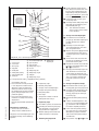
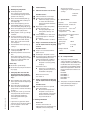
Operating Instructions
Self Drying Vacuumpump
PM 200
INNOVATIVE
TECHNOLOGY
WORLDWIDE
Operating Instructions
PM 16633-842.3
Self Drying Pumps
Laboratory Vacuum Pumps
with Drying System
PM 16633-842.3
You have selected a high-quality KNF product; the following tips will help you operate it safely, and reliably over
a long period of time.
Carefully study operating instructions before using the pumps and observe at all times the relevant instructions
to avoid dangerous situations.
0. List of Contents
1. Description, Operating
Conditions
2. Safety
3. Installation
4. Operation
5. Servicing
6. Trouble Shooting
7. Ordering Information
8. Specifications
KNF resrve the right to make changes
1.
Description,
Operating Conditions
The pumps transfer, and evacuate 100
% oil-free. In operation they are gastight, and maintenance-free.
The self drying pumps make it possible
during evacuation to blow the condensed liquid out of the pump heads at
high speed, while maintaining the
vacuum in the recipient at a constant
level. After drying the pump heads the
pumps achieve a greatly improved
vacuum and evacuate much faster
than pumps without a drying system.
Warning
When the pumps are operating the following ambient conditions must be
maintained:
The interval between pump head
ventilation operations (t3).
2. Safety
This pump model is equipped with the
solenoid valve for ventilating the pump
heads. The scope of delivery does not
include control electronics.
1.1 Electrical Equipment
See section 8 for full electrical
data.
The pumps are fitted with a thermal
-switch to protect against overloading.
1.2 Operating Conditions
The pumps and/or the drying
system must not be used in
areas where there is a danger of
explosion.
These pumps must not be used if
the entry of air into the pump
during venting (drying system)
could result in the creation of reactive, explosive or otherwise hazardous mixtures.
Prior to any use of the pump ensure that the creation of reactive,
explosive or otherwise hazardous
mixtures during the supply of air is
prevented.
For maximum permissible operating
pressure, ultimate vacuum, and
flow capacity: see chapter 8.
sign below are only allowed to be
opened after pulling out the plug
(disconnecting the power source).
Use only original KNF replacement
parts.
1.3 Ambient Condition
The duration of the ventilation of
the pump heads (t2)
The time between switching on the
drying system and the first ventilation of the pump heads (t1)
= Position in the illustration, = Important point, = Task, = Advise to users,
If your potential application lies outside
the above limits discuss it with our
technical adviser (see last page for
contact telephon number).
The pumps and/or the drying
system must not be used in
areas where there is a danger of
explosion.
Ambient temperature during operation: between + 5 °C .... + 40 °C.
During operation an adequate
supply of air for cooling must be
provided.
The control for the drying system is
effected via soleonid valve and three
variables:
PM 1633-842.3-3.00 e 11/05 Symbols:
The pumps must not be used for
liquids. You will find suitable liquid
pumps in our Product Program.
Note that the pumps may only be
used for their intended purpose.
The pumps and/or the drying
system must not be used in
areas where there is a danger of
explosion.
These pumps must not be used if
the entry of air into the pump
during venting (drying system)
could result in the creation of reactive, explosive or otherwise hazardous mixtures.
Prior to any use of the pump ensure that the creation of reactive,
explosive or otherwise hazardous
mixtures during the supply of air is
prevented.
Components connected to the
pumps must be designed to withstand the pneumatic performance
of the pumps (see chapter 8).
Plug the pump only into properly
installed grounded outlets.
When the operation of the pump is
interrupted by the thermal switch, it
will re-start automatically after
cooling down. Take all care necessary to prevent this leading to a
dangerous situation.
Specific safety instructions and
measures for the media being
handled must be observed.
Parts of the casing marked with the
2
3.
Installation
Choose a safe location (flat surface for the pump).
Install the pump so as to ensure
adequate flow of air cooling.
Connect the suction and pressure
lines (tube ID 10 mm).
Arrange the pressure line so
that condensate can flow out
of the the pump (falling pipe).
The condensate is conducted out
of the pump via the pressure line.
A container is to be installed to
catch the condensate.
The solenoid valve must be
connected to the drying system
control electronics (not included in
scope of delivery); see fig. 1.
Plug the pump only into properly
installed grounded outlets.
Compare the supply data with the
elecetrical data of the pump. The
voltage must not vary by more than
+ 10 %, and -10 % from that shown
on the type-plate.
4. Operating Instructions
4.1 Operating Conditions
The pumps and/or the drying
system must not be used in
areas where there is a danger of
explosion.
These pumps must not be used if
the entry of air into the pump
during venting (drying system)
could result in the creation of reactive, explosive or otherwise hazardous mixtures.
Prior to any use of the pump ensure that the creation of reactive,
explosive or otherwise hazardous
mixtures during the supply of air is
prevented.
Specific safety instructions for the
media being handled must be
observed.
Valve voltage 24 V DC
blue (-)
for tube ID 10
brown (+)
231
Mains switch
Fig. 1: Pump PM 16633-842.3-3.00
The pumps must not start against
pressure. This also applies when
the pump restarts after the power
has been cut off for a short period.
The components to be connected
to the pump must be designed to
withstand the pneumatic data of
the pumps (see Section 8).
The maximum permissible operating pressure (1 bar g) must not be
exceeded.
To prevent the maximum permissible operating pressure being
exceeded, restriction or control of
the air or gas flow should only be
carried out in the suction line.
If restriction or control of the air or
gas flow is made on the pressure
side ensure that the maximum permissible operating pressure is not
exceeded.
When the pump is at a standstill
the inlet and the outlet must be at
normal atmospheric pressure.
PM 1633-842.3-3.00 e 11/05
Ensure the pump outlet is not closed or restricted.
Diaphragm and valve plates are the
only parts subject to wear. Wear is
usually indicated by a drastic
reduction in the pneumatic performance. When replacing parts proceed as described in section 5.
Ambient conditions: see chapter
1.3.
4.2 Operation
Taking the pump into operation
Plug the mains plug of the pump
into a properly installed safety
socket.
Switch the pump on at the pump
mains switch (see fig. 1).
If cyclic drying of the pump heads
is required in the current evacuation process, switch the drying
system on at the mains switch of
the control (not included in
scope of delivery).
The drying system should only
be switched on if a container
has been attached to the pressure line of the pump which will
catch the condensate; otherwise the condensate will flow
out uncontrolled.
Check:
Tubing for correct tubing.
Electrical connections for correct
connection.
After the evacuation/process has been
completed, take the pump out of operation:
Purge the pump including the
connecting hoses with air at full
3
flow rate for about 5 minutes.
If the drying system is switched
on:
Switch the drying system off at the
mains switch of control system
(not included in scope of delivery).
Switch the pump off at the mains
switch of the pump.
Pull the mains plug of the pump out
of the socket.
5.
Servicing:
Changing Diaphragms and Valve
Plates/Sealings
The structured diaphragms in both
pump heads should be changed at the
same time. When diaphragms are
changed, valve plates/sealings should
also be replaced. If the diaphragms are
not changed in both heads at the same
time or diaphragms and valve plates/
sealings are not changed at the same
time the nominal performance of the
pump is not guaranteed after the service.
If a pump has been used for
aggressive or toxic substances or
other types of substances which
are hazardous, hazardous to health,
or injurious, the following points
must be observed:
1.) Clean the pump and its compo-
Orientation of disk
springs Pump N 842_ has a round shape of head
Specification
Screw (12x)
Screw (3x)
Disk spring
Top plate
Head plate
Valve plate/sealing
Intermediate plate
Guide pin
Structured diaphragm
Spacer (thick)
Spacer (thin)
Dampening ring A
Screw
Dampening felt
Dampening ring B
Adapter
Dampening ring C
Dampening
diaphragm
PM 1633-842.3-3.00 e 11/05
Required tools and material:
Service Set (see section 7)
Philips-head screwdriver No. 2.
Change the structured diaphragms and
valve plates/sealings in the following
sequence:
a.)
b.)
c.)
d.)
e.)
f.)
c.) Change structured diaphragms
Push down one structured diaphragm until other diaphragm is
pushed upwards to its highest
position.
Carefully unscrew the higher
strucutred diaphragm anti-clock
wise using both hands.
Replace all spacers / onto the
screw thread of the new structured diaphragm (same number and
order)
Screw in the new structured diaphragm and tighten it by hand;
you do not need any tool.
Change the second structured diaphragm as described above (step
to ) for the first.
Changing the two diaphragms one
after the other ensures that the
same number of diaphragm spacers are refitted as were removed.
This is essential to maintain the
pneumatic performance of the
pump.
Fig. 2: Pump head for N 842.3_ (exploded drawing, symbolic)
nents before servicing.
2.) Ensure that the service personnel
is not subject to a health hazard.
Apply the safety and protection
measures that are necessary for
the medium that has been handled
by the pump (example: the use of
protective gloves).
3.) Ensure that discarded parts and
materials are safely and correctly
disposed of.
Use only original KNF replacement
parts.
On the pneumatic head connections, loosen one of the union nuts
by hand. Then slightly loosen the
angle-fitting in the pump head by
turning it anticlockwise, so that the
connecting tube can be pulled out.
Loosen the outer screws on
each pump head.
Carefully remove both pump heads
(top plate , head plate and
intermediate plate ).
The soleonid valve of the
drying system remains fitted
in this situation.
Preparatory steps
Remove pump heads
Change structured diaphragms
Change valve plates/sealings
Refit pump heads
Final steps.
d.) Change valve plates/sealings
Unscrew the three screws in
the top plate of one pump head.
Carefully remove top plate and
head plate from intermediate
plate ; exposing the valve plates/sealings .
The postion numbers in the following text refer to fig. 2.
Remove old valve plates/sealings
.
a.) Preparatory Steps
Shut down system (see section 4.2)
If there should be deposits in the
recesses in the intermediate plate
, clean them until the deposits
have been completly removed.
including disconnecting the pump
from the power source (pull out
plug of electrical supply unit).
Remove tubing from the inlet and
outlet connectors of the pump.
b.) Removing the pump heads
4
Insert new valve plates/sealings
in the recesses in the intermediate plate (upper and lower
sides of the valve plates/sealings
are identical).
Carry out the steps to for the
second pump head.
6.
e.) Refitting the pump heads
At one pump head:
Press the lip on the edge of the
structured diaphragm into the
groove in the housing.
Place the intermediate plate ,
with the valve plates/sealings on
the adapter .
Place the head plate on the
intermediate plate in the position indicated by the guide pin .
Place the top plate on the head
plate in the right position.
Gently tighten screws in diagonal order.
Screw in the three screws in
the centre of the pump top plate until they are flush with the top
plate; then screw one final half
turn to tighten.
For orientation of disk springs see fig. 2.
Carry out steps to for the
second pump head.
! Refit the pneumatic head connection:
Place tube onto the connecting
part of the angle fitting, turn angle
fitting to a straight position and
tighten the union nut.
f.) Final steps
Reconnect system tubing.
Reconnect the pump to the electricity supply.
PM 1633-842.3-3.00 e 11/05
If the pump does not reach the
desired vacuum after changing
diaphragms and valve plates/sealings:
Check whether the spacers have
been replaced onto the diaphragm
screw thread.
Check the interconnecting pipework connection between both
pump heads as well as the tubing
for leaks.
Possibly the screws on one of
the pump heads (or both heads)
are insufficiently tightened
(carefully tighten them again
crosswise).
Troubleshooting
Sufficient vacuum is not reached
Order No.
057359
Possible reasons:
Tube connections are not tight
Condensate in the pump head
Switch the drying system on
or reduce the interval between pump head ventilation
operations.
Diaphragms and/or valve plates/
sealings are worn out
Changing diaphragms and
valve plates/sealings: see
section 5.
If this problem occurs after changing of diaphragms or valve plates/sealings:
See information in section 5.
Pump is switched on, but does not
run, the on/off-switch on the pump
is not lit
Possible reasons:
Pump is not connected with the
power source.
No voltage in the power source.
Fuse in the pump is defective (only
authorized/qualified personnel
should investigate this problem):
Disconnect the pump from
the power source by pulling
out plug.
8.
Permissible ambient
temperature:
+5... +40°C
Hose connection for tube ID 10 mm
Voltage pump:
230 V
Frequency:
50 Hz
Power consumption pump:
220 W
Fuse pump
(2 x):
3.15 T [A]
IP 44
Voltage soleonid
valve
24 V DC
CE - Safety Demands
The pumps correspond to the
safety regulations of the EU low
voltage directive 73/23 EWG and of
the EU directive concerning electromagnetical compatibility 89/336
EWG. The requirements of the following harmonised standards are
fulfilled:
EN 55014
EN 61000-6-1
EN 61000-6-3
EN 61000-3-2/3
EN 61010-1
The pumps correspond to IEC 664:
Dimension of the fuse:
see section 8.
Pump is switched on, but does not
run, the on/off-switch on the pump
is lit
Possible reason:
The thermal switch has opened
due to overheating
Disconnect the pump from
the power source, let the
pump cool down, investigate
the reason for the overheating and irradicate it.
Service Set
A Service Set contains all
replacement parts needed for one
complete service of the pump.
5
Specifications
Capacity:
max. 34 l/min
Ultimate vacuum: 4 mbar abs
Permissible operating pressure:
max. 1 barg
Placement of fuse:
The fuse is accessible after
opening the marked cover at
the bottom of the pump.
7. Ordering Information
If you have any questions about
servicing call our technical adviser
(see last page for contact telephone number).
Service Set contains
2 diaphragms and 4 valve plates/
sealings
the overvoltage category II
the pollution degree 2.
Appendix:
Customer statement for
repair order (sample
statement for copying)
In order for KNF to repair the
pump, the customer must provide
a statement on the media which
were pumped and on pump
cleaning. Please fill out the corresponding KNF form, and submit
it together with the pump.
Statement/Certificate
We confirm that the pump
model listed below
(please specify)
.............................................
.............................................
.............................................
Serial-No. (please specify)
.............................................
.............................................
.............................................
was used to pump the following media:
.............................................
.............................................
.............................................
.............................................
.............................................
.............................................
.............................................
and that the pump listed
above was cleaned. There
are no poisonous, aggressive, biological, radioactive or other dangerous
media in the pump.
PM 1633-842.3-3.00 e 11/54
................
Company
......................
Date/
Signature
KNF Neuberger GmbH
Alter Weg 3
D-79112 Freiburg
Tel. ++49/7664/5909-0
Fax ++49/7664/5909-99
E-Mail: [email protected]
www.knf.de
english
25.11.2005
D 08851