1
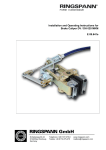
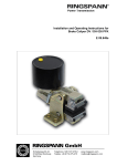
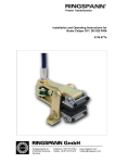
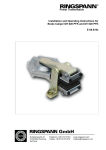
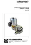
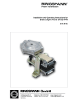
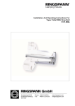
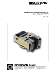
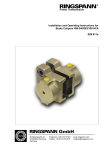
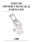
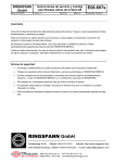
Power Transmission Installation and Operating Instructions for Brake Caliper DH 012 FEM E 09.731e Schaberweg 30-34 61348 Bad Homburg Germany Telephone +49 6172 275-0 Telefax +49 6172 275-275 www.ringspann.com [email protected] Installation and Operating Instructions for Brake Caliper DH 012 FEM spring activated – electromagnetic released 110/230VAC, 50...60 Hz Issue: 18.06.2013 Version : 2 drawn: Su checked: Su E 09.731e Pages: 11 Page: 2 Important Please read these instructions carefully before installing and operating the product. Your particular attention is drawn to the notes on safety. These installation and operating instructions are valid on condition that the product meets the selection criteria for its proper use. Selection and design of the product is not the subject of these installation and operating instructions. Disregarding or misinterpreting these installation and operating instructions invalidates any product liability or warranty by RINGSPANN; the same applies if the product is taken apart or changed. These installation and operating instructions should be kept in a safe place and should accompany the product if it is passed on to others – either on its own or as part of a machine – to make it accessible to the user. Safety Notice Installation and operation of this product should only be carried out by skilled personnel. Repairs may only be carried out by the manufacturer or accredited RINGSPANN agents. If a malfunction is indicated, the product or the machine into which it is installed, should be stopped immediately and either RINGSPANN or an accredited RINGSPANN agent should be informed. Switch off the power supply before commencing work on electrical components. Rotating machine elements must be protected by the purchaser to prevent accidental contact. Supplies abroad are subject to the safety laws prevailing in those countries. Installation and Operating Instructions for Brake Caliper DH 012 FEM spring activated – electromagnetic released 110/230VAC, 50...60 Hz Issue: 18.06.2013 Version : 2 drawn: Su checked: Su Contents 1 General information 2 Configuration and function 3 Drawing and parts list 4 Condition on delivery 5 Installing the RINGSPANN brake caliper 5.1 5.2 5.3 5.4 5.5 6 Installation Brake caliper electrical connection Brake caliper adjustment Electrical connection for the inductive proximity switch Running-in procedure Maintenance 6.1 6.2 6.3 6.4 General maintenance Checking / adjusting braking force Permissible brake pad wear and exchange of the brake pads Emergency release E 09.731e Pages: 11 Page: 3 Installation and Operating Instructions for Brake Caliper DH 012 FEM spring activated – electromagnetic released 110/230VAC, 50...60 Hz Issue: 18.06.2013 1. Version : 2 drawn: Su checked: Su E 09.731e Pages: 11 Page: 4 General information These installation and operating instructions apply to: the DH 012 FEM with left-mounted electromagnet as shown in Fig. 3.1 in Section 3, for mounting on a 12.5 mm thick brake disc. the DH 012 FEM with right-mounted electromagnet. various types of brake-pads, e.g. with wear alarm cable, increased glide speed, double friction surface or other special brake pad materials. supply voltage 110VAC and/or 230VAC An identification plate with a 16-digit part number is affixed to the caliper. The precise design of the brake caliper is defined by this part number only Please consult the drawings in each section when using these instructions. 2. Configuration and function The brake caliper is used as a parking and stopping brake. Braking force is generated by the spring (5). The brake is released (opened) with the aid of an electromagnet (1). Brake pad (2) wear reduces brake holding and stopping force, as it lessens tension in the spring. If the event of brake pad wear resulting from operation, the brake must be inspected and adjusted as described in Section 6.2. The operating status “brake calliper open” can be checked with the aid of an inductive proximity switch (10) mounted on the brake lever with electromagnet. Technical data for the proximity switch are provided in Section 5.4: Electrical connection for the inductive proximity switch. Rotating parts (e.g. brake discs) must be secured by the purchaser to prevent contact. Danger to life and limb! It is essential to secure the entire drive train against inadvertent starts during brake installation and maintenance. Rotating components can cause severe injuries. Therefore, rotating components (e.g. brake disc) must be secured by the operator to prevent accidental contact. Installation and Operating Instructions for Brake Caliper DH 012 FEM spring activated – electromagnetic released 110/230VAC, 50...60 Hz Issue: 18.06.2013 3. Version : 2 drawn: Su checked: Su E 09.731e Pages: 11 Page: 5 Drawing and parts list Parts list: Part 1 2 Nomenclature Quantity Part number Electromagnet DH 12 FEM 230 VAC 1 3514.014.101.000000 Electromagnet DH 12 FEM 110 VAC 1 3514.014.100.000000 Standard brake pad BK6800 2 2472.005.013.A00112* Brake pad BK8006 2 2472.005.013.A00117* Brake pad BK6905 2 2472.005.013.A00109* Electronics DH 12 FEM 230 VAC 1 3515.072.101.000000 Electronics DH 12 FEM 110 VAC 1 3515.072.100.000000 4 * Part number for 1 brake pad. For the unique assignment of the identical Parts must specify the part number of the brake on the identification plate Installation and Operating Instructions for Brake Caliper DH 012 FEM spring activated – electromagnetic released 110/230VAC, 50...60 Hz Issue: 18.06.2013 4. Version : 2 drawn: Su checked: Su E 09.731e Pages: 11 Page: 6 Condition on delivery The brake caliper are delivered with electromagnet, electronics and inductive proximity switch. The brake caliper have a clamping gap of approx. 10.5 mm between the brake pads (2). The electromagnet under tension opens the brake caliper on the preset clamping gap of 13.1 mm (brake disk thickness 12.5 and an air gap of 0.3 mm reciprocally between the brake disc and the brake pads). 5. Installing the RINGSPANN brake caliper Before installing the brake, the brake disc must be cleaned with alcohol, e.g. ethyl or isopropyl alcohol, or a water-based surfactant solution (soapy water, etc.) and then rubbed dry with a clean cloth. When cleaning the brake disc with a thinner, acetone or a brake cleaning agent, it is important to ensure that neither these cleaners nor any cleaner residues come in contact with the brake pads. This is especially important in the case of brakes used only as parking brakes, as no dynamic braking operations take place during which thinner residues would be rubbed off the brake disc. Caution! Oil and rust-proofing-agent residues reduced friction coefficient and thus diminish transmissible braking torque substantially. 5.1 Installation The brake caliper should be mounted to stabile, vibration-free machine components in order to ensure noise-free, non-screech. During installation, it is essential to ensure that brake pads are centred and in full contact with the brake disc (the midlines of the brake lever must point to the midpoint of the brake disc.). Maximum permissible lateral brake disc wobble is 0.2 mm. Greater wobble may cause rattling and shaking of the brake unit. Preparing to installation The brake caliper must be released prior to installation on the brake disc with 12.5 mm thickness This can be accomplished: with the aid of the electromagnet, provided it has been connected to a power source (see Section 5.2) mechanically, by loosening the lock nut (7) and screw (6) by turning clockwise screwed into the lever and thus the gap between the brake pads increases. Caution! Danger of injury! With air of the brake caliper the spring (5) becomes set under tension. If the electromagnet not constantly gets the correct current supply, parts of the brake can move suddenly relatively to each other! Installation and Operating Instructions for Brake Caliper DH 012 FEM spring activated – electromagnetic released 110/230VAC, 50...60 Hz Issue: 18.06.2013 Version : 2 drawn: Su checked: Su E 09.731e Pages: 11 Page: 7 Caution! If the screw (6) solved for the installation, all steps must 5.2 to 5.4 after the installation of the brake necessarily carried out for a fully functional brake caliper! The brake caliper is mounted to the machine component with using two M12 bolts (strength class 8.8). 5.2 Brake caliper electrical connection Caution! Danger of damage! Before connecting the brake caliper to a power source, ensure that your power supply conforms to the specifications for nominal voltage and power frequency on the identification plate. If voltage and frequency do not conform to specifications, the brake calliper must not be connected to the system, as otherwise the electronics and/or the electrical release may be irreparably damaged. Unzulässige Nominal voltage: 110 VAC or 230 VAC depending on the electromagnet, 50...60 Hz, single-phase. Circuit-breaker : 6A (the security with 6A is to be placed by the user surely). Cable : up to a length of 50 m: 1.5 mm², fine gage. length of 50 m or more: 2.5 mm², fine gage. Outside diameter 5....10 mm. Caution! Check to ensure that the brake disc rotates freely! Brief surges of up to 4 A (for a very few 100 ms) occur when the switch is activated. A step-down transformer may be used to reduce voltage, provided the transformer has a capacity of at least 0.3 kVA. Installation and Operating Instructions for Brake Caliper DH 012 FEM spring activated – electromagnetic released 110/230VAC, 50...60 Hz Issue: 18.06.2013 Version : 2 drawn: Su checked: Su E 09.731e Pages: 11 Page: 8 Connect the main power cable as shown in Fig. 5.1. Ensure that the cable passage is completely sealed in order to prevent the intrusion of water into the terminal box. Connector DIN 43650 Ensure secure protective lead connection! Tighten threaded gasket! Tighten cover screws! L N The connections L and N may be exchanged. Fig. 5.1 Connection to power supply 5.3 Brake caliper adjustment Have you solved the screw (6) for mounting the caliper, you must necessarily proceed from paragraph 5.3.1. For installation of the brake caliper was connected and turned on the electromagnet current, then the caliper opens to the factory default setting of 0.3 mm on both sides of the brake pads. There is no uniform air gap divided on the brake pads, proceed in accordance with paragraph 5.3.2 or make new justage the brake caliper in accordance with paragraph 5.3.1 5.3.1 Air gap adjustment Loosen by switched-on electromagnet the three lock nuts (1x pos. 7 and 2x pos. 8) and turn the screw (6) into the thread of the brake lever and the two threaded pins (3) so far back into the lever so that the levers more play gotten and the air gap at the brake pads becomes larger. Press a brake pad (2) to the brake disk on and turn the screw (6) against the summit of the spring guide bushing out of the thread, until at the other brake pad (2) the desired air gap (maximally 0.6 mm) is reached. Note: We recommend adjusting the total brake gap by inserting a feeler gauge with the thickness of the total brake gap between the brake disc and the brake pad (2) and turning the screw (6) to the point at which the feeler gauge can just barely be pulled out of the gap. Note: The minimum necessary air gap depends on the existing lateral brake disc wobble. It must be guaranteed that the brake pads (2) do not grind in the ventilated condition of the brake caliper to the brake disc. The smaller the air gap adjusted is, the more largely is the wear reserve, before the brake calliper must be set. Lock the screw (6) with the lock nut (7). Installation and Operating Instructions for Brake Caliper DH 012 FEM spring activated – electromagnetic released 110/230VAC, 50...60 Hz Issue: 18.06.2013 Version : 2 drawn: Su checked: Su E 09.731e Pages: 11 Page: 9 5.3.2 Mediate of the air gap Depending upon the position of the brake disc axis, the electromagnet (1) mounted on the side can generate a tilting moment that causes one brake pad (2) to touch the brake disc. This would result in constant rubbing of that pad (2) against the disc. The brake gap can be mediated uniformly using one of the two threaded pins. Turn the threaded pins (3) on the arm on which the brake pad has the larger gap counter-clockwise to the point at which the gap is equal on both sides of the brake disc. Secure that treaded pin (3) with the nut (8). Set the opposite threaded pin (3) such a so that a minimal air gap between the knoll and the stop of about 0.1 mm remains. Lock also this threaded pin (3) with the nut (8). Caution! It is necessary to ensure that the friction pads (2) do not grind in the open position of the caliper on the disc! aufs führen! If now the caliper is de-energized switched, the full braking torque (holding torque) is available. 5.4 Electrical connection for the inductive proximity switch A DC 12V02PSLK inductive proximity switch manufactured by DIEL is installed: Switching function Operating voltage Voltage drop Temp. range Connection : PNP (closer) : 10....35 V DC : < or = 1.5 V : -25 to +80°C : 2 m PVC cable Switching distance : 2 mm flush-mountable Max. op. current : 0...200 mA Polarity reversal-resistant : yes Safety class : IP 67 Housing : M12x1 V4A Fig. 5.2 Circuit diagram, PNP technology The proximity switch (Figure 2.1, item 10) is arranged so that at this electrically attracted armature of the electromagnet (caliper is open) is attenuated by the spring guide bushing (the LED lights). If the electromagnet is de-energized, the brake caliper is applied and the spring guide bush moves out of the field of inductive proximity switch out (it is no longer damped) the LED goes off. Procedure for installing or replacing the proximity switch: The following instructions apply to the proximity switch listed above, with 2-mm switching distance. Installation and Operating Instructions for Brake Caliper DH 012 FEM spring activated – electromagnetic released 110/230VAC, 50...60 Hz Issue: 18.06.2013 Version : 2 drawn: Su checked: Su E 09.731e Pages: 11 Page: 10 To prevent the connecting cable from twisting, mount the proximity switch before making the electrical connection. When electromagnet are switched on, turning the proximity switch (10) in the bore of the holding plate, until it is abuts on the leadership of the spring bushing. From this position, turning the proximity switch again carefully about ½ to 1 turns counter-clockwise back. Secure this position with the locknut. Connect the proximity switch on with a load. The encoder LED should light up. Test the proper function by repeatedly operating the brake caliper. When operate the brake caliper, the LED must react safely and regular (light up). 5.5 Running-in procedure Optimum braking effect is achieved only when both brake pads (2) have full contact with the brake disc and the pads have been heated briefly to approx. 200°C. Therefore, repeated brief braking actions (warm-up) while the brake disc is rotating are recommended. The brake pads are the been run-in when the friction surface shows a contact pattern of at least 70 to 80% and short-term local heating of the surface area of about 200°C was reached. Caution! If running-in is not performed, the braking forces cited in our catalogue no. 46 cannot be achieved. Reductions of up to 50% are possible! aufs führen! 6. Maintenance Brake caliper maintenance should be performed at intervals of 4 to 12 weeks, depending upon the frequency and duration of operation. 6.1 General maintenance Check both brake lever for ease of movement. Clean all bearings and glide points. Lubricate all bearing and glide points. Caution! Brake pads (2) must not be come in contact with lubricants! aufs führen! Check for tight bolt / screw connections: Brake caliper to machine component Electromagnet (1) at the brake lever Inductive proximity switch and bracket Visual inspection of the electrical connections Installation and Operating Instructions for Brake Caliper DH 012 FEM spring activated – electromagnetic released 110/230VAC, 50...60 Hz Issue: 18.06.2013 Version : 2 drawn: Su checked: Su E 09.731e Pages: 11 Page: 11 6.2 Checking /adjusting braking torque With increasing brake pad wear increases themselves the relaxation of the spring (5) in the closed state of the caliper (brake position: electromagnet (1) de-energized). This reduces the braking torque! If the gap between the brake pad and the brake disc on each side amounts to 1 mm (total gap 2 mm), the caliper must be readjusted as described in paragraph 5.3. 6.3 Permissible brake pad wear and exchange of brake pads Brake pad material must have a thickness of at least 5 mm (from the top surface of the brake pad to the top surface of the steel mounting plate) Brake pads or brake linings must always be replaced in pairs. Required tools: Fixed spanner or ring spanner SW 13 Fixed spanner or ring spanner SW 24 Allen key SW 6 Feeler gauge. Caution! Ensure that the mass held by the brake is secured against shifting or twisting, as the brake must be released (opened) in order replace the brake pads! aufs führen! Danger to life and limb! Brake pads may be replaced only when plant or the Working machine are at a standstill! Ensure that the mass held by the brake is secured against twisting, as the brake must be released (opened) in order replace the brake pads. aufs führen! aufs führen! 6.4 Emergency release No current supply is present can the brake be ventilated also manually. Loosen for this lock nut (7) and turn the hexagonal screw (6) into the thread of the lever until the spring (5) and the brake disc can be turned. Caution! After manually releasing the brake, all steps 5.3 must be necessarily carried out!