1
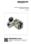
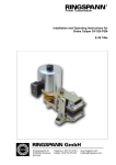
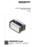
Power Transmission Installation and Operating Instructions for Brake Calipers HW 040/063/100 HFA E09.611e Schaberweg 30-34 61348 Bad Homburg Germany Telephone +49 6172 275-0 Telefax +49 6172 275-275 www.ringspann.com [email protected] Date: 14.03.2014 Installation and Operating Instructions for Brake Calipers HW 040/063/100 HFA hydraulically activated E 09.611 e Issue : 11 Pages: 19 drawn: Su checked: Su Page: 2 IMPORTANT Please read these instructions carefully before installing and operating the product. Your particular attention is drawn to the notes on safety. These installation and operating instructions are valid on condition that the product meets the selection criteria for its proper use. Selection and design of the product is not the subject of these installation and operating instructions. Disregarding or misinterpreting this installation and operating instructions invalidates any product liability or warranty by RINGSPANN; the same applies if the product is taken apart or changed. These installation and operating instructions should be kept in a safe place and should accompany the product if it is passed on to others – either on its own or as part of a machine – to make it accessible to the user. Safety Notice Installation and operation of this product should only be carried out by skilled personnel. Repairs may only be carried out by the manufacturer or accredited RINGSPANN agents. If a malfunction is indicated, the product or the machine into which it is installed, should be stopped immediately and either RINGSPANN or an accredited RINGSPANN agent should be informed. Switch off the power supply before commencing work on electrical components. Rotating machine elements must be protected by the purchaser to prevent accidental contact. Supplies abroad are subject to the safety laws prevailing in those countries. Date: 14.03.2014 Installation and Operating Instructions for Brake Calipers HW 040/063/100 HFA hydraulically activated E 09.611 e Issue : 11 Pages: 19 drawn: Su checked: Su Contents 1. General remarks 1.1 General safety instructions 1.2 Special safety instructions 2. Configuration and function / Parts list 2.1 Function 2.2 Markings 2.3 Drawing and parts list 3. Proper use / specified purpose 4. Improper use 5. Condition upon delivery 6. Handling and storage 7. Technical requirements for safe and reliable operation 8. Installation of the RINGSPANN brake caliper 8.1 General instructions for assembly and installation 8.2 Assembly and installation 8.3 Setting / adjusting brake pad gap 8.4 Installing the threaded connection and bleeding the brake 8.5 Connecting the signal cable (optional for organic brake pads) 9. Commissioning 10. Disassembling the brake 11. Lubrication 12. Maintenance 12.1 General maintenance 12.2 Permissible brake pad wear and replacement of the brake pads 12.3 Replacing seals, strippers and piston gaskets Page: 3 Date: 14.03.2014 1. Installation and Operating Instructions for Brake Calipers HW 040/063/100 HFA hydraulically activated E 09.611 e Issue : 11 Pages: 19 drawn: Su checked: Su Page: 4 General remarks 1.1 General safety instructions Please read theses installation and operating instructions carefully before installing and operating the brake calipers. Please refer to the drawings in the various sections. Safety must be given the highest priority during all work performed on the brake. Switch off the drive unit before performing work on the brake. Rotating components (e.g. brake disc) must be secured by the operator to prevent accidental contact. 1.2 Special safety instructions Danger to life and limb! It is essential to secure the entire drive train against inadvertent starts during brake installation and maintenance. Rotating components can cause severe injuries. Therefore, rotating components (e.g. brake disc) must be secured by the operator to prevent accidental contact. 2. Configuration and function / Parts list 2.1 Function The brake calipers HW 040 HFA, HW 063 HFA and HW 100 HFA are machine components used for the purpose of braking accelerated masses safely and reliably. The combination of brake caliper and brake disc provides a complete brake unit capable of securing machines and equipment system effectively. Thanks to its universal design, it can perform the following functions: As a holding or parking brake, it prevents the unintended start of a stationary shaft. As a stopping brake, it brings a rotating shaft to a complete standstill. Braking force is generated by hydraulic pressure. The brake caliper is released by spring force. 2.2 Markings These installation and operating instructions apply to: brake caliper HW 040 HFA, HW 063 HFA and HW 100 HFA the standard version HW xx HFA; „F“ after the size designation stands for "spring released“. the version without spring released the different friction materials for friction pads, friction pads with glued Wolverine-plate and for friction pads with signal cable. for installation on a vertical brake discs in combination with horizontal shafts! For horizontal disc we ask for consultation. Date: 14.03.2014 Installation and Operating Instructions for Brake Calipers HW 040/063/100 HFA hydraulically activated E 09.611 e Issue : 11 Pages: 19 drawn: Su 2.3 Drawings and Parts Lists Fig. 2.1 HW 040 HFA Parts list: HW 040 HFA Part Nomenclature Quantity 1 Brake housing 2 2 Piston 2 3* Set: Standard Brake pad BK 4773 1 3* Set: Brake pad BK 4773 with 4m fiberglass optic signal cable 1 3* Set: Brake pad BK 8006 1 3* Set: Brake pad T544 1 3* Set: Brake pad BK4773 with 5m signal cable 1 4 Sleeve 2 5 Bushing 2 6 Holding bracket 2 checked: Su Page: 5 Date: 14.03.2014 Installation and Operating Instructions for Brake Calipers HW 040/063/100 HFA hydraulically activated E 09.611 e Issue : 11 Pages: 19 drawn: Su 7 Piston gasket QUAD-RING (see Section 12.3) 2 8 Pressure spring 2 9 Circlip 2 10 Shim 2 11 Grip ring G 6x1 6 12 Cylindrical pin 6x20-A-St 2 13 Clamping sleeve 4X16 DIN EN ISO 8752 2 14 Head screw (for holding bracket) 2 15 Head screw 2 16 USIT-ring U4,5X7,0X1,0 2 * for the unique assignment is the material number of the brake required checked: Su Page: 6 Date: 14.03.2014 Installation and Operating Instructions for Brake Calipers HW 040/063/100 HFA hydraulically activated E 09.611 e Issue : 11 Pages: 19 Fig. 2.2 drawn: Su HW 063 HFA Parts list: HW 063 HFA Part Nomenclature Quantity 1 Brake housing 2 2 Piston 2 3* Set: Standard Brake pad BK 4773 1 3* Set: Brake pad BK 4773 with 0.2m signal cable 1 3* Set: Brake pad BK 8006 1 3* Set: Brake pad T544 1 3* Set: Brake pad BK4773 with 5m signal cable 1 4 Sleeve 2 5 Bushing 2 6 Holding bracket 2 7 Piston gasket QUAD-ring (see Section 12.3) 2 checked: Su Page: 7 Date: 14.03.2014 Installation and Operating Instructions for Brake Calipers HW 040/063/100 HFA hydraulically activated E 09.611 e Issue : 11 Pages: 19 drawn: Su 8 Pressure spring 2 9 Circlip 2 10 Shim 25x35x1 DIN 988 2 11 Grip ring G 8x1 12 12 Cylindrical pin 2 13 Clamping sleeve 4 14 Head screw (for holding bracket) 2 15 Head screw 2 16 USIT-ring (see Section 12.3) 2 * for the unique assignment is the material number of the brake required checked: Su Page: 8 Date: 14.03.2014 Installation and Operating Instructions for Brake Calipers HW 040/063/100 HFA hydraulically activated E 09.611 e Issue : 11 Pages: 19 Fig. 2.3 drawn: Su HW 100 HFA Part list: HW 100 HFA Part Nomenclature Quantity 1 Brake saddle housing 2 2 Piston 2 3* Set: Standard Brake pad BK 4773 1 3* Set: Brake pad BK 6800 1 3* Set: Brake pad BK 6230 1 3* Set: Brake pad BK 8006 1 4 Sleeve 2 5 Bushing 2 6 Holding plate 4 7 Piston gasket 2 8 Pressure spring 2 checked: Su Page: 9 Date: 14.03.2014 Installation and Operating Instructions for Brake Calipers HW 040/063/100 HFA hydraulically activated E 09.611 e Issue : 11 Pages: 19 drawn: Su 9 Circlip 2 10 Shim 40X50X1 DIN 988 2 11 Grip ring G 16x1,5 12 12 Cylindrical pin 2 14 Head screw (for holding bracket) 4 15 Head screw 2 16 USIT-ring (see Section 12.3) 2 17 Spacer bushing 4 18 Spring washer 4 checked: Su Page: 10 * for the unique assignment is the material number of the brake required 3. Proper use / specified purpose The brake caliper may be used only in systems with a maximum hydraulic pressure of 90 bar and in accordance with the technical data. In the standard type HFA (with spring release) ventilate the brake pads down to a residual pressure in the hydraulic < 0.4 bar. An automatic wear adjustment ensures constant piston stroke. The brake caliper is designed for use as a holding/parking brake and/or a stopping brake. Other uses are improper and incompatible with the specified purpose. RINGSPANN assumes no liability for damages resulting from improper use. The risk is assumed by the user alone. 4. Improper use Operating the brake caliper under higher pressure than that specified in the technical data or with other media is prohibited. Unauthorized constructive modifications of the brake caliper are similarly prohibited. RINGSPANN assumes no liability for damages resulting from improper use. The risk is assumed by the user alone. 5. Condition upon delivery The brake caliper is tested prior to delivery. Test pressure is 100 bar. The delivered consignment consists of 2 brake caliper halves and 1 set of brake pads. 6. Handling and storage The weight of the caliper depending on the execution between 5.5 kg and 30 kg. The brake is delivered with anti-corrosion protection and can be stored in an enclosed, dry space for up to 12 months. It is important to prevent condensation from forming. Moist storage areas are unsuitable. Brakes stored for longer than 12 months and after each transport, the brake must be activated at least once in order to prevent sticking of the seal. Date: 14.03.2014 7. Installation and Operating Instructions for Brake Calipers HW 040/063/100 HFA hydraulically activated E 09.611 e Issue : 11 Pages: 19 drawn: Su checked: Su Page: 11 Technical requirements for safe and reliable operation Mounting the brake to stable, low-vibration machine components ensures low-screech, low-noise braking. 8. Installation of the RINGSPANN brake caliper 8.1 General instructions for assembly and installation Before installing the brake caliper, the brake disc must be cleaned with alcohol, e.g. ethyl or isopropyl alcohol or a water-based surfactant solution (soapy water, etc.) and then rubbed dry with a clean cloth. When cleaning the brake disc with a thinner, acetone or a brake cleaning agent, it is important to ensure that neither these cleaners nor any cleaner residues come in contact with the brake pads. This is especially important in the case of brakes used only as parking brakes, as no dynamic braking operations take place during which thinner residues would be rubbed off the brake disc. Caution! Oil and rust-proofing-agent residues reduced friction coefficient and thus diminish transmissible braking torque substantially! 8.2 Assembly and installation Caution! The brake caliper must not be exposed to hydraulic pressure during assembly/installation. Prior to installation, check to ensure that the mounting surface is even and concentric run between the brake disc and the mounting surface is within the tolerance range of 0.3 mm. Ensure that the parallel gap of 0.2 mm between the brake disc and the mounting surface is not exceeded. Check the axial movement of the brake disc. Axial movement must not exceed ± 0.3 mm. Maximum permissible lateral brake disc wobble is 0.1 mm. Greater wobble may cause rattling and shaking of the brake unit. Caution! Check to ensure that the brake disc rotates freely. Date: 14.03.2014 Installation and Operating Instructions for Brake Calipers HW 040/063/100 HFA hydraulically activated E 09.611 e Issue : 11 Pages: 19 drawn: Su checked: Su Page: 12 Securing the brake caliper to stable, low-vibration machine elements guarantees low-screech and low-noise braking. The two halves of the brake caliper are attached with screws or threaded bolts to the mounting plate or the machine components. The width of the mounting plate between the two brake caliper halves should equal brake disc thickness plus 3 mm. The gap on each side must measure exactly 1.5 mm in order to prevent additional axial pressure on the brake disc shaft during braking operations. Please use screws/bolts of quality grade 10.9 or 12.9. Type Number of screws/bolts Screw/Bolt size Tightening torques* grade 10.9 grade 12.9 HW 040 HFA 2 M 12 123 Nm 144 Nm HW 063 HFA 2 M 16 302 Nm 354 Nm HW 100 HFA 4 M 24 1017 Nm 1190 Nm *) calculated with µK = µG = 0.12 as the average coefficient of friction in the thread bores (from VDI Guidelines 2230, version 2001). 8.3 Setting / adjusting the brake pad gap The setting of the distance of the brake pads takes place after the mounting of the brake caliper automatically. The gap between the brake pads and the brake disc should always be approx.1 mm on each side. During installation, ensure that the brake pads are centred and in full contact with the surface of the brake disc. Caution! During installation, ensure that the brake pads are centred and in full contact with the surface of the brake disc. The gap between the brake pads and the brake disc should always be approx. 1.5 mm on each side. Please observe maximum the wear limit. 8.4 Installing the threaded connection and bleeding the brake Hydraulic hoses should be used as hydraulic fluid and fluid drain lines. The connection is connected to one of the two pressure oil connections. The other bore is used as a vent bore. Install on the vent hole a miniature test ports or an automatic venting system is previously the closing screw to remove. The hydraulic system must be bled during initial installation, when seals are changed or other work is performed on the hydraulic system. Date: 14.03.2014 Installation and Operating Instructions for Brake Calipers HW 040/063/100 HFA hydraulically activated E 09.611 e Issue : 11 Pages: 19 drawn: Su checked: Su Page: 13 If the hydraulic fluid circulation system is configured, the hydraulic system can be bled alternatively by circulating the hydraulic fluid. Caution! Oil expelled from the system must be removed completely. Leaks must be repaired immediately. Connection threading: HW 040 HFA HW 063 HFA HW 100 HFA = G 1/4“ = G 1/4“ = G 3/8“ Hydraulic fluid: Alloyed mineral oil equivalent to Group HLP (DIN 51525 or API classification SC, SD or SE. The hydraulic line is connected to one of the two bores in the brake caliper halves. The second bore serves as a bleeder bore and must be sealed with a threaded plug. Hydraulic fluid quantities: HW 040 HFA for 2.0 mm piston stroke per caliper half: 2.5 cm3, per caliper: 5 cm3 3 3 Total cylinder volume per caliper half: 10 cm , per caliper: 20 cm HW 063 HFA for 3.2 mm piston stroke per caliper half: 10 cm3, per caliper: 20 cm3 Total cylinder volume per caliper half: 39 cm3, per caliper: 78 cm3 HW 100 HFA for 4,5 mm piston stroke per caliper half: 35,5 cm3, per caliper: 71 cm3 3 3 Total cylinder volume per caliper half: 146 cm , per caliper: 292 cm Check to ensure that screws and other connections are tight: brake caliper to machine component Check the following for absence of leaks: bolt connections and other connections Caution! The hydraulic system must never be operated at a higher pressure than the approved. The maximum operating pressure is 90 bar. Date: 14.03.2014 Installation and Operating Instructions for Brake Calipers HW 040/063/100 HFA hydraulically activated E 09.611 e Issue : 11 Pages: 19 drawn: Su checked: Su Page: 14 Information! The purer the hydraulic fluid, the longer the service life of the brake system. aufs führen! Caution! It is important to ensure that the brake pads do not rub against the brake disc when the brake caliper is open. 8.5 Connecting the signal cable (optional for organic brake pads) Connect the signal cable via a signal lamp to a 24V power source. If the maximum permissible brake pad wear limit is reached, contact to the neutral conductor is effected and the signal light goes on. Fig. 8.1 9. Commissioning The entire surface of both brake pads must be in contact with the brake disc in order to achieve the optimum braking effect. The brake pads must also be heated briefly to approx. 200°C. Therefore, multiple brief braking operations under low hydraulic pressure are required to heat the brake pads. Date: 14.03.2014 Installation and Operating Instructions for Brake Calipers HW 040/063/100 HFA hydraulically activated E 09.611 e Issue : 11 Pages: 19 drawn: Su checked: Su Page: 15 Caution! If the brakes are used as holding brakes, the braking torques can not be attained. Reduction of the braking torques of up to 50% are possible. 10. Disassembling the brake Danger to life and limb! When disassembling the brake it is essential to ensure that the entire drive train is secured against inadvertent activation. Rotating components can cause severe injuries. Therefore, rotating components (e.g. brake discs) must be secured against accidental contact. Drain the oil pressure from the hydraulic system. Caution! Ensure that no hydraulic pressure is applied to the brake caliper. Drain hydraulic fluid completely. Caution! Secure the brake for disassembly. Disconnect the hydraulic lines from the brake caliper. Secure the brake for disassembly. Remove the screws used to hold the brake in place. The brake caliper can now be removed from the mounting surface. 11. Lubrication Oil or grease all bearings and sliding surfaces when available. Caution! Brake pads must not come in contact with lubricants. Date: 14.03.2014 Installation and Operating Instructions for Brake Calipers HW 040/063/100 HFA hydraulically activated E 09.611 e Issue : 11 Pages: 19 drawn: Su checked: Su Page: 16 12. Maintenance 12.1 General maintenance Maintenance must be performed on the brake caliper at intervals of 4 weeks up to once a year, depending upon the operating load. Perform the following checks during every maintenance operation: Check brake pads for wear Check the bolt connection between the brake caliper and the machine component as well as the bolt connections for the retaining plates for tightness. Check hydraulic lines and connections for leaks. Inspect the brake piston gaskets for tight seal by checking the leak oil lines. If there is oil in the leak oil lines, the gaskets must be replaced. Observe fluid change intervals! Change mineral after every 8.000 hours or operation or once per year. Caution! Brake pads must not come in contact with hydraulic fluid. 12.2 Permissible brake pad wear and replacement of the brake pads Danger to life and limb! Brake pads may be replaced only when the equipment system and/or the working machine is at a complete standstill! Caution! Brake pads must always be replaced in pairs. Before replacing the brake pads, ensure that the mass held by the brake is secured to prevent movement, as parts of the brake must be loosened/removed for replacement. Caution! Ensure that the brake caliper is not under hydraulic pressure before replacing the brake pads. Date: 14.03.2014 Installation and Operating Instructions for Brake Calipers HW 040/063/100 HFA hydraulically activated E 09.611 e Issue : 11 Pages: 19 drawn: Su checked: Su Page: 17 Permissible brake pad wear Brake pads must always be replaced in pairs! Pads must be replaced with the thickness of the mounting plate and the remaining pad material is reduced to the following values: HW model: Thickness in mm 040 060 100 5 8 15 Ensure that the hydraulic fluid line is free of residual pressure, e.g. by removing the bleeder plug, as fluid is forced back into the system during brake pad replacement. Replacing brake pads for HW 040 HFA and HW 063 HFA - Remove the holding brackets hold the brake pads in place. - Pull the brake pads out of the brake caliper halves with pliers (attached to removal cams). - Press the piston completely into the brake housing. - Insert the new brake pads and attach the holding brackets. - Ensure that brake pad material is free of oil and grease. Replacing brake pads for HW 100 HFA - Remove the two inner mounting bolts and the spacer bushings. - Pull the brake pads out of the brake caliper halves with pliers (attached to removal cams). - Press the piston completely into the brake housing. - Insert the new brake pads. Replace the spacer bushings and tighten the mounting bolts to the specified torque. - Alternatively, if sufficient space is available, you may replace the brake pads by removing the holding plates (6) toward the inside (direction of brake disc axle). Date: 14.03.2014 Installation and Operating Instructions for Brake Calipers HW 040/063/100 HFA hydraulically activated E 09.611 e Issue : 11 Pages: 19 drawn: Su checked: Su Page: 18 12.3 Replacing seals, strippers and piston gaskets HW 040 HFA + HW 063 HFA HW 063 HFA HW 100 HFA HW 100 HFA Danger to life and limb! Seals/gaskets may be replaced only with the equipment system and/or working machine is at a complete standstill! Caution! Ensure that no hydraulic pressure is applied to the brake caliper. Observe the manufacturer’s instructions when handling solvents. Maximum cleanliness is essential during work on the hydraulic system. Every part must be cleaned with a solvent, dried and stored dust-free. Dirt shortens the life of seals and gaskets significantly. Inspect the surfaces of the brake housing and the brake pistons. Surface damage may destroy seals/gaskets immediately. Date: 14.03.2014 Installation and Operating Instructions for Brake Calipers HW 040/063/100 HFA hydraulically activated E 09.611 e Issue : 11 Pages: 19 drawn: Su checked: Su Page: 19 Replacing of piston gasket For HW 040 to HW 100 (without retraction) - Disconnect the brake caliper from the machine component and remove the brake pads. Close one connection bore in the brake housing with a plug. Connect the other bore to a hydraulic hand pump. Hold or clamp the brake housing firmly in place. Press the piston out with the hand pump. Replace the piston gaskets. Press the piston with a press or a plastic hammer into the cylinder bore of the brake housing to the stop point and ensure that it is centred. For HW 040 HFA to HW 100 HFA (with retraction) - Remove the brake caliper and replace the gaskets as described above. - Before pressing in the piston, centre the gripper rings (1) in the piston (2) relative to the bore or to the outside circumference of the piston with a tapered pin. - Press the piston with a press into the cylinder bore of the brake housing to the stop point and ensure that it is centred. Fig. 12.1 Piston gaskets: Type Gasket typ HW 040 HFA HW 063 HFA HW 100 HFA Dimension B (mm) Gasket part no. Quad ring with support ring 5,4 +0,2 5134-047003-000000 5137-040401-000000 Quad ring with support ring 6,6 +0,2 5134-073004-000000 5137-063304-000000 Rod gasket Type B, profile BA 9,6 +0,25 5155-063081-000000 Rod gasket Type B, profile BA 12,1 +0,25 5155-100081-000000 Grooved ring Type C1 7,5 +0,2 5155-100001-000000 Grooved ring Type N100-11 6,9 +0,2 5138-100301-000000