1
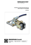
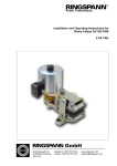
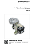
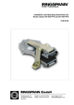
® Power Transmission Installation and Operating Instructions for Brake Caliper DV / DH 020 FKM E 09.677e Schaberweg 30-34 61348 Bad Homburg Germany Telephone +49 6172 275-0 Telefax +49 6172 275-275 www.ringspann.com [email protected] Installation and Operating Instructions for Brake Caliper DV 020 FKM and DH 020 FKM spring activated – manually released Issue: 26.05.2014 Version : 4 drawn: Su checked: Su E 09.677e Pages: 11 Page: 2 IMPORTANT Please read these instructions carefully before installing and operating the product. Your particular attention is drawn to the notes on safety. These installation and operating instructions are valid on condition that the product meets the selection criteria for its proper use. Selection and design of the product is not the subject of these installation and operating instructions. Disregarding or misinterpreting these installation and operating instructions invalidates any product liability or warranty by RINGSPANN; the same applies if the product is taken apart or changed. These installation and operating instructions should be kept in a safe place and should accompany the product if it is passed on to others – either on its own or as part of a machine – to make it accessible to the user. SAFETY NOTICE Installation and operation of this product should only be carried out by skilled personnel. Repairs may only be carried out by the manufacturer or accredited RINGSPANN agents. If a malfunction is indicated, the product or the machine into which it is installed, should be stopped immediately and either RINGSPANN or an accredited RINGSPANN agent should be informed. Switch off the power supply before commencing work on electrical components. Rotating machine elements must be protected by the purchaser to prevent accidental contact. Supplies abroad are subject to the safety laws prevailing in those countries. Installation and Operating Instructions for Brake Caliper DV 020 FKM and DH 020 FKM spring activated – manually released Issue: 26.05.2014 Version : 4 drawn: Su Contents 1. General remarks 2. Configuration and function 3. Drawing and parts list 4. Condition on delivery 5. Installing the RINGSPANN brake caliper 5.1 Installation 5.2 Connecting the pull cable to the handbrake lever 5.3 Pull cable-connection (delivery status) at the brake caliper 5.4 Starting up 5.5 Running-in procedure 6. Maintenance 6.1 General maintenance 6.2 Checking and adjusting braking force 6.3 Brake pads – checking brake pad wear and replacing pads checked: Su E 09.677e Pages: 11 Page: 3 Installation and Operating Instructions for Brake Caliper DV 020 FKM and DH 020 FKM spring activated – manually released Issue: 26.05.2014 1. Version : 4 drawn: Su checked: Su E 09.677e Pages: 11 Page: 4 General information This installation and operation instructions applies to: the DV 20 FKM, brake caliper mounted parallel to the brake disc (frame construction V, see Fig. 3.1 in Section 3). Pull cable mounted on the right. the DV 020 FKM; pull cable mounted on the left. the DH 020 FKM, brake caliper mounted at the right angle to the brake disc (frame construction H, see Fig. 3.2 in Section 3). for installation on a brake disc with the thickness of 12.5 mm. the version handbrake lever with electric switch kit the version with pull cable without handbrake lever. the version with special pull cable without handbrake lever. the version without pull cable and without handbrake lever the version with special brake pad material An ID plate with a 16-place part number is mounted on the brake caliper. The precise design of the brake caliper is defined by this part number only. Please consult the drawings in each section when using this instruction. 2. Configuration and function The brake caliper is used as a parking brake. Braking force is generated by a spring. The brake is released (opened) mechanically by a pull cable. By moving the lever (see Fig. 5.1 in Section 5.2) above the zero-point (self-arresting), the brake remains in an open state. When brake pads are worn, holding force is reduced. Brake pads must then be checked for wear and adjusted as described in Section 6.2. Rotating parts must be secured by the user against inadvertent contact (e.g. brake disc). Danger to life and limb! It is essential to secure the entire drive train against inadvertent starts during brake installation and maintenance. Rotating components can cause severe injuries. Therefore, rotating components (e.g. brake disc) must be secured by the operator to prevent accidental contact. Installation and Operating Instructions for Brake Caliper DV 020 FKM and DH 020 FKM spring activated – manually released Issue: 26.05.2014 3. Version : 4 Drawing and parts list Fig. 3.1 Fig. 3.2 drawn: Su checked: Su E 09.677e Pages: 11 Page: 5 Installation and Operating Instructions for Brake Caliper DV 020 FKM and DH 020 FKM spring activated – manually released Issue: 26.05.2014 Version : 4 drawn: Su E 09.677e checked: Su Pages: 11 Page: 6 Parts list: Part Nomenclature Quantity Part number 1V Brake caliper DV 020 FKM without pull cable and without lever 1 4457-201706-000000 1H Brake caliper DH 020 FKM without pull cable and without lever 1 4457-200706-000000 2 Pull cable for brake caliper DV and DH 020 FKM for RINGSPANN brake lever 1 4584-809092-Ryyyyy*** Standard brake pad 2 2472-005013-A00112* Brake pad from BK 6905 2 2472-005013-A00117* (Fig. 5.1) Handbrake lever B 50452 1 4561-000001-R50452 5 Fastening clamps for cable size L and M 3 * Part number. for 1 brake pad 4. 1563-001006-R00000 *** yyyyy = cable length in cm Condition at delivery The brake unit – consisting of the brake caliper, brake cable and handbrake lever – is delivered fully assembled. The brake is not operable as delivered, as the pressure spring is fully compressed and secured with 2 screws M5x40 DIN EN ISO 4762 (see Fig. 5.2 in Section 5.3). Consequently, the brake caliper is set with a gap of approx. 14 mm between brake pads, which allows for installation/mounting without the need to engage the handbrake lever. If the unit is delivered without a pull cable, the pressure spring is mounted as shown in Fig. 5.3 in Section 5.3. 5. Installation of the RINGSPANN brake caliper Before installing the brake, the brake disc must be cleaned with alcohol, e.g. ethyl or isopropyl alcohol, or water-based surfactant solution (soapy water, etc.) and then rubbed dry with a clean cloth. When cleaning the brake disc with a thinner, acetone or a brake cleaning agent, it is important to ensure that neither these cleaners nor any cleaner residues come in contact with the brake pads. This is especially important in the case of brakes used only as parking brakes, as no dynamic Braking operations take place during which thinner residues would be rubbed off the brake disc. Caution! Oil and rust proofing agent residues reduce friction coefficients and thus diminish transmissible braking torque substantially! Installation and Operating Instructions for Brake Caliper DV 020 FKM and DH 020 FKM spring activated – manually released Issue: 26.05.2014 Version : 4 drawn: Su checked: Su E 09.677e Pages: 11 Page: 7 5.1 Installation The brake caliper should be mounted to stabile, vibration-free machine components in order to ensure noise-free, screechless braking. During installation, it is essential to ensure that brake pads are centred and in full contact with the brake disc (the midlines of the brake arm must point to the midpoint of the brake disc). Maximum permissible lateral brake disc wobble is 0.2 mm. Greater wobble may cause rattling and shaking of the brake unit. The brake caliper is mounted to the machine component with using 2 M12 bolts (with frame construction V) or 1 M 20 bolt (with frame connection H) the strength class 8.8. In order to ensure uniform lift-off (ventilation) of the friction pads from the brake disc, you may make an attachment of the pull cable until after the first bending radius, see Fig. 3.1 and/or Fig. 3.2. The bending radius in the pull cable routing must be at least 127 mm. The handbrake lever is with two M8 screws of strength class 8.8 attached to the machine parts. Make sure that you have between the two lever plates each arranged loosely included mounting sleeve, see cutting A - A in Fig. 5.1. If the pull cable through openings and holes are must conducted, for which the handbrake lever is too large, the cable can be removed from the handbrake lever, see Section 5.2. 5.2 Connecting the pull cable to the handbrake lever Bild 5.1 Fig. 5.1 The pull cable is connected to the handbrake lever by the manufacturer. The pull cable can be detached if necessary using the following procedure: Remove the pin (Pos.10, Fig. 5.1), after setting aside the safety splint pin and put the washer to the side. Swing the connecting link out of the fork head. Loosen the lock nut M18x1.5 (Pos.11, Fig. 5.1) Remove the brake lever from the hose sleeve by turning to the left. The connecting link may not be in the fork head, otherwise the cable stranded wire is twisted. Installation and Operating Instructions for Brake Caliper DV 020 FKM and DH 020 FKM spring activated – manually released Issue: 26.05.2014 Version : 4 drawn: Su checked: Su E 09.677e Pages: 11 Page: 8 You install the pull cables in reverse order, pay attention to this case the distance 20 mm. Do not forget to secure the pin (Pos.10, Fig. 5.1) ) by means of splint pin! 5.3 Pull cable-connection (delivery status) at the brake caliper Fig. 5.2 Fig. 5.3 If the brake caliper was ordered without a pull cable, or is not mounted on the brake caliper, mounting condition see Fig. 5.3, remove the transport screw M8x55 DIN EN ISO 4762 and the washer 8,4 DIN 7349. The cable end by means of the two nuts M18x1.5 attach on the brake lever shown in Fig. 5.2, install the cable at a distance "E" of 10 mm and tighten the two nuts on tightly. Slide the pre-tensioned spring unit over the end of the stranded wire. First turn the nut M8 DIN 439 onto the threaded end of the cable strand then then the hexagon cap nut M8 DIN 917 until it stops then secure the hexagon cap nut by tightening the nut M8 DIN 439. 5.4 Starting up Before starting up the gap and hence the holding torque and braking torque must be adjusted. Please note: The adjustable minimum gap depends on the actual degree of brake disc wobble. The smaller the gap is set, the greater is the holding torque and the wear reserve before the brake caliper must be adjusted. Remove the two nuts M18x1.5 on the handbrake lever. Set the gap between the two brake pads by shifting the axial position of the hose sleeve and the pull cable. If you increase dimension “E”, the gap is reduced, and vice-versa. Set a small gap (from 0.2 to 0.4 mm) on each side, but ensure that the brake pads do not rub against the brake disc. Secure the pull cable in position by tightening the nuts (M18x1.5) against the handbrake lever. Caution! Once the installation and adjustment procedures are completed, the two transport and installation screws (M5x40 DIN EN ISO 4762) and corresponding nuts (M5) must be removed in order ensure proper brake caliper function (see Fig. 3.1 and Fig. 5.2)! Only then is the brake caliper fully operable and capable of applying the correct holding and braking torque. At this point, the gap between the two spring plates should be set at approx. 21.5 mm (the brake lever is not positioned over the zero point). Installation and Operating Instructions for Brake Caliper DV 020 FKM and DH 020 FKM spring activated – manually released Issue: 26.05.2014 Version : 4 drawn: Su checked: Su E 09.677e Pages: 11 Page: 9 Adjusting the handbrake lever: Turn the adjusting knob on the handbrake lever to the stop point, which is the lower end position of the adjusting bolt (minimum cable stroke and minimal force applied to the handbrake lever). Then swing the handbrake lever over the zero point. If the brake caliper do not open to the correct gap setting or the pressure spring is not compressed to dimension 19.5 mm, swing the lever back to the closed brake position. Turn the adjusting knob clockwise ½ revolution, swing the lever over the zero point again and check the gap and dimension 19.5. Repeat this operation until you reach dimension 19.5 mm and the correct gap setting at the zero point. By turning the adjusting knob clockwise, you gradually increase the cable stroke and the forced applied to the handbrake lever. The spring cannot be compressed to less than 19.0 mm, as this would cause the two spring plates to abut. If you continue to turn the adjusting knob clockwise, you will no longer be able to return to the zero point. Caution! If the adjusting knob is turned too far to the right and an attempt is made to shift the handbrake lever over the zero point, the brake cable or the brake cable may be destroyed! The brake caliper is now fully functional. The handbrake lever now has two end positions: Brake caliper “open”; the handbrake lever shifted upward over the zero point by 6° to 8° (and fixed in that position). The pressure spring is compressed; the brake disc rotates freely. (The gap between the two spring plates measures approx. 19.5 mm) Brake caliper “closed”; the handbrake lever is shifted downward over the zero point. The pressure spring presses the two brake levers apart; the brake disc is clamped. The brake is engaged. (The gap between the two spring plates measures approx. 21.5 mm). 5.5 Running-in procedure Optimum braking effect is achieved only when both brake pads (3) are in full contact with the brake disc and the brake pads have attained a temperature of approx. 200°C. A few times, short brake when the brake disc rotates, is therefore necessary. Caution! If breaking-in is not performed, the braking forces cited in our catalogue no. 46 cannot be achieved. Reductions of up to 50% are possible. 6. Maintenance Maintenance should be performed on the brake calliper at intervals of 4 to 12 weeks, depending upon the frequency and duration of operation. Installation and Operating Instructions for Brake Caliper DV 020 FKM and DH 020 FKM spring activated – manually released Issue: 26.05.2014 Version : 4 drawn: Su checked: Su E 09.677e Pages: 11 Page: 10 6.1 General maintenance Check both brake caliper lever for ease of movement. Clean all bearings and glide points Lubricate all bearing and glide points. Caution! Brake pads must not be come in contact with lubricants. Check for tight bolt / screw connections: brake caliper to machine component brake pads to brake caliper lever handbrake lever to machine component 6.2 Checking and adjusting braking force As the brake pads are worn, tension is reduced in the pressure springs when the brake caliper is closed and the gap of 21.5 mm between the spring plates is enlarged (the handbrake lever is below the zero point). The result is reduced holding/braking torque. This changed the angle of the handbrake lever and the adjustment bolt is approaching the upper end position (Fig. 5.1). If the upper limit position is reached or the adjustment bolts (10) is touch at the end of the groove, can not be further relaxed the pressure spring. At this point, at the latest, the gap must be readjusted as described below: When the brake caliper is close (the handbrake lever is not above the zero point), measure the actual gap between the two spring plates and calculate the difference between the measured gap and the original setting of 21.5 mm. The brake gap must be readjusted by this value. Measure dimension “E“ (see Fig. 3.1 and 3.2 and/or Fig. 5.2). Open the brake caliper by push the handbrake lever beyond over the zero point. The pressure spring is compressed. Loosen the two nuts M18x1.5 on the connection between the push cable and the handbrake lever (see Fig. 5.2) and turn nut “R” toward the brake cable by the calculated readjustment value. By shifting the axial position of the hose sleeve you enlarge dimension “E” by the calculated readjustment value. Secure the new position of the brake cable by tightening the nuts M18x1.5 against the brake lever. Open and close the brake caliper. Measure the gap again. The gap between the two spring plates should be approx. 21.5 when the brake is closed and 19.5 when the brake is open. The brake pads must nut rub against the brake disc. Repeat the entire adjustment procedure if necessary. Installation and Operating Instructions for Brake Caliper DV 020 FKM and DH 020 FKM spring activated – manually released Issue: 26.05.2014 Version : 4 drawn: Su checked: Su E 09.677e Pages: 11 Page: 11 6.3 Brake pads – checking brake pad wear and replacing pads The degree of brake pad wear is determined on the basis of two criteria. If one of these criteria is fulfilled, the brake pads must be replaced. If the adjusting bolt on the handbrake lever reaches the upper end position or the bolt (10) abuts with the end of the slot when the brake caliper is closed, pressure spring tension cannot be further reduced and sufficient braking force can no longer be applied. If nut “R” also abuts with the cuff of the hose sleeve (see Fig. 5.2), no further adjustment is possible. The brake pads must be replaced. The brake pad material must not be worn to within less than 4 mm (residual brake pad thickness) to the steel base plates! Brake pads or brake linings (Pos.3) must always be replaced in pairs. Fixed spanner or ring spanner SW 13 are required to remove and replace the brake pads. Remove the brake pad screws (the brake caliper must be closed). Move the hand brake lever beyond the zero point (remains fixed in this position). Remove the two nuts M18x1.5 on the connection between the pull cable and the handbrake lever (see Fig. 5.2) and set dimension “E” to 10 mm by shifting the axial position of the hose sleeve. Secure the position of the pull cable by tightening the nuts M18x1.5 against the handbrake lever. Replace the worn brake pads. Close the brake caliper by shifting the position of the handbrake lever and tightening the brake pad screws. Readjust the brake caliper as described in Section 5.4.