1
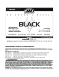
Operating Instructions for C3F8 Supply Lines
ATLAS Project Doc. No:
Institute Doc. No:
Created: 28/4/2004
Modified: 26/1/05
Page: 1 of 12
Rev: C
Operating Instructions for C3F8 Supply Lines
This manual gives instructions for purging, evacuating, and filling the C3F8 cooling
system, and connecting/disconnecting discs to the cooling system.
Prepared by:
N.P. Hessey
Checked by:
Nobody
Distribution List:
A-P. Colijn, H. Boer Rookhuizen, P. Werneke, R. Buis
Approved by:
Nobody
ATLAS Project Document No:
Page: 2 of 12
Rev. No.: C
History of Changes
Rev. No.
A
B
C
Date
28/4/04
28/7/04
26/1/05
Pages
All
Many
Many
Made by
NP Hessey
NP Hessey
NP Hessey
Description of changes
Original document
Safety warnings + dP protection + new fig. 1 etc.
V13 and 14; many small improvements learnt
from experience.
List of Figures
1
Supply lines between C3F8 Plant and Test Boxes, with valve labels. . . . . . . . .
3
Contents
1
Operation 1: Flush With Nitrogen
5
2
Operation 2: Evacuate lines to atmosphere
6
3
Operation 3: Fill Plant With C3F8
7
4
Operation 4: Preparing for Disc Cooldown
4.1 Operation 4.1: Flushing with Nitrogen . . . . . . . . . . . . . . . . . . . . . . . .
4.2 Operation 4.2: Evacuating to Atmosphere . . . . . . . . . . . . . . . . . . . . . .
4.3 Operation 4.3: Filling with C3F8 . . . . . . . . . . . . . . . . . . . . . . . . . . .
8
8
9
9
5
Operation 5: Evacuating C3F8 to Plant and Preparing For Disc Removal
10
6
Operation 6: Final Removal of C3F8
6.1 Operation 6.1: Removal of most of the C3F8 . . . . . . . . . . . . . . . . . . . .
6.2 Operation 6.2: Recuperation of residual C3F8 gas . . . . . . . . . . . . . . . . . .
11
11
12
ATLAS Project Document No:
Page: 3 of 12
Rev. No.: C
Introduction
This document gives instructions for operating the C3F8 cooling system for the ATLAS SCT Discs.
The cooling system can broadly be split into four components: the C3F8 Cooling Plant (“C3F8
Plant”), the supply and return lines with their associated valves, vacuum system, purge lines etc.
(“Supply Lines”); the disc test box (“Disc Box”); and the cylinder test box (“Cylinder Box”). Figure
1 shows how the supply lines interconnect the cooling plant with the test boxes, and labels the valves
with the names used in this document.
R
V
Vent to
atmosphere
Version 4, 26/1/05
V12
Vacuum
pump
V11
Pvac
N2 Supply
V7
V9
V13
V8
V6
V10
Disc test
box
C3F8 plant
Fridge
V2
V4
FM2
SV
FM1
V5
V1
V3
By−pass valve
Filter
Vent to
atmosphere
Cylinder
test box
V14
FM1: precision low−rate flow meter. Used
to set restrictors and check individual
circuit flows.
FM2: High rate flow meter, used for
monitoring most of the time.
Figure 1: Supply lines between C3F8 Plant and Test Boxes, with valve labels.
Certain operations can cause damage to equipment, loss of C3F8 (which is expensive and bad
for global warming), or risk of personal injury. Hence it is important to follow the instructions
closely. Use gloves to avoid contact with cold surfaces. Use goggles if there is a risk of C3F8
escape, especially relevant if adjusting the restrictors.
Once the Cooling Plant and Supply Lines are ready for use, they have to be filled with C3F8.
ATLAS Project Document No:
Page: 4 of 12
Rev. No.: C
This requires a sequence of operations detailed below: Operation 1 (Flush lines with nitrogen);
Operation 2 (Evacuate lines to atmosphere); Operation 3 (Fill plant with C3F8).
Thereafter each time a disc is put in a circuit Operation 4 (Preparing for Disc Cooldown) has to
be carried out.
Each time the disc tests are finished, Operation 5 (Preparing for Disc Removal) has to be carried
out before removing a disc or opening its cooling circuits.
In the event of problems with the C3F8 Plant or the Supply Lines, and at the end of all tests, the
C3F8 has to be removed from the system. Operation 6 (Final Removal of C3F8) achieves this.
For all operations, start the DCS and make sure at least one inlet and one outlet electro-valves
are open to the differential pressure sensor: this will avoid putting too large a pressure across it.
Valves V13 and V14: these were added later, and are not mentioned in the instructions.
They should generally be left open. They are for the specific purpose of leak checking the on-disc
cooling circuits: by reducing the closed-off volume, they make the check more sensitive.
ATLAS Project Document No:
Page: 5 of 12
Rev. No.: C
1 Operation 1: Flush With Nitrogen
Initial state: Compressor off; liquid pump off; vacuum pump off; C3F8 Plant, Supply Lines, and
any disc circuits full of air at atmospheric pressure. N 2 bottle closed.
If preparing for initial C3F8 fill, connect the C3F8 bottle to the schraeder valve first, with the
bottle-valve closed. Then the connecting tube is also purged with N2 and evacuated.
Step
1
2
3
4
5
6
Action
Close V4, V5, V6, V7
Close V9, V11, V12
Open V1, V2, V3, V10 and SV
in C3F8 plant
Set nitrogen pressure regulator
to 0 bar (anti-clockwise); Open
V8; slowly raise regulator pressure till you hear gas flowing
Wait till flushed
Close V8 then V3 immediately
after
Result/Comments
Disc Box and Cylinder Box isolated from system
Vacuum pump isolated from system
Flush circuit is open and at atmospheric pressure
Flushing begins (gently, avoiding damage to flow
meters)
Circuit is full of dry nitrogen at atmospheric pressure
Flushing stops; circuit is sealed
Final state: The circuit is full of dry nitrogen, sealed from the atmosphere.
Note: Leak checks can be carried out by pressurising the lines via V8 with V3 closed, and
watching how fast the pressure drops. Make sure the circuit is leak-tight before proceeding.
ATLAS Project Document No:
Page: 6 of 12
Rev. No.: C
2 Operation 2: Evacuate lines to atmosphere
Initial state: Compressor off, liquid pump off, vacuum off; circuit full of dry nitrogen at atmospheric pressure; V3, V4, V5, V6, V7, V8, V9, V11, V12 closed; V1, V2, V10 open; i.e. following
Operation 1.
DO NOT CARRY OUT THIS OPERATION WITH C3F8 IN THE SYSTEM!
Step
1
2
3
4
5
6
7
Action
Check all valves are in the appropriate initial state
Check Pvac is about 1 bar absolute; if above, open V3 briefly to
bring down to 1 bar; if below,
open V8 briefly to top up with
dry nitrogen
Close V1 and V2
Open V12 and turn on the vacuum pump
Open V9
Wait till Pvac and other pressure
meters show circuit is evacuated
(about 1 mbar)
Close V12 and V9 then turn vacuum pump off
Result/Comments
Safety of flow meters, vacuum pump etc.
Avoid putting excess pressure on vacuum pump
Prevent reverse flow through flow meters
Inlet side of vacuum pump pressure drops
Circuit evacuation starts
Circuit is evacuated with remnant dry nitrogen
Final state: C3F8 Plant and Supply Lines are at vacuum from V6/V7 to V1/V2, with 1 mbar
dry nitrogen. Circuit lines from V1/V2 to V4/V5 have nitrogen at 1 bar. Circuit lines from V4/V5
to V6/V8 unchanged.
The circuit can again be checked for leaks by watching how fast the pressure rises. Do not
proceed until the circuit is leak tight.
ATLAS Project Document No:
Page: 7 of 12
Rev. No.: C
3 Operation 3: Fill Plant With C3F8
Initial state: Compressor off, liquid pump off, vacuum off; circuit full of dry nitrogen at vacuum of
1 mbar; V1, V2, V3, V4, V5, V6, V7, V8, V9, V11, V12 closed; V10 open. C3F8 bottle on scales,
connected to schraeder valve, with bottle valve closed. I.e. following Operation 2.
Step
1
2
3
4
5
6
7
8
9
Action
Record weight of C3F8 bottle
Check/put (safely) all valves are
in the appropriate initial state
Check Pvac is low (below
30 mbar on DCS)
Close V10
Open valve on C3F8 bottle.
Turn on compressor (separate instructions), cool HE1 to minimum temperature (See C3F8
plant instructions)
Watch weight of C3F8 bottle.
When desired amount (3 kg =
2 l) transferred, close valve on
C3F8 bottle
Remove C3F8 tube from
schraeder valve, replace seal on
valve.
Turn compressor off
Date
21/10/04
21/10/04
Time
85.5
82.5
Weight (kg)
09:00
09:45
Result/Comments
So you know when to stop.
Safety of flow meters, vacuum pump etc.
Do not waste C3F8 by mixing it with moist air etc.
Isolate C3F8 Plant from supply pipes
C3F8 Plant is full of C3F8 gas at about 6.9 bar g
C3F8 evaporates in bottle and condenses in HE1.
Desired quantity of C3F8 is in the C3F8 Plant
Bottle can be removed to storage
C3F8 pressure rises slowly to about 6.9 bar g.
Comments
Start cooling and open valve
Close bottle valve
Table 1: Bottle weight history
ATLAS Project Document No:
Page: 8 of 12
Rev. No.: C
4 Operation 4: Preparing for Disc Cooldown
In the following, V4, V6 and V13 apply to the Disc Box; V5, V7 and V14 apply to the Cylinder
Box.
4.1 Operation 4.1: Flushing with Nitrogen
Initial state: Compressor off, liquid pump off, vacuum pump off; C3F8 Plant full of warm C3F8 at
about 6 bar; supply lines full of air at pressure of 1 bar; disc cooling circuits connected up and
sealed; unused cooling circuits in test boxes sealed off; V1, V2, V3, V4, V5, V6, V7, V8, V9, V10,
V11, V12 closed.
Step
1
2
3
4
5
6
7
Action
Check all Supply Line valves are
closed and supply lines on discside of V1, V2, V10 have no
C3F8 in (or maximum 1 mbar
C3F8 as after Operation 5)
Open (V4 and V6) or (V5 and
V7)
N2 regulator to 0; Open V8;
slowly raise N2 regulator to high
pressure (e.g. 19 bar g); close
V8
Open V3
Set nitrogen regulator to about
2 bar and open V8
Wait for sufficient flushing
Close V8 followed soon after by
V3
Result/Comments
Avoid loss of C3F8 to atmosphere
Circuit is open for flushing
Allows leak check: see how quickly the pressure
drops. Probably want to close inlet valves on disc
and V13 or V14.
Vent the nitrogen to atmosphere
Flushing starts. Note the disc circuits are flushed
“backwards”
Supply Lines and disc cooling circuits are full of dry
nitrogen
Flushing stops; circuit is sealed
Final state: C3F8 Plant is full of warm C3F8; Supply Lines and disc circuits are full of dry
nitrogen at about atmospheric pressure.
Do not proceed until the circuit is leak tight.
ATLAS Project Document No:
Page: 9 of 12
Rev. No.: C
4.2 Operation 4.2: Evacuating to Atmosphere
Initial state: Compressor off, liquid pump off, vacuum pump off; C3F8 Plant full of warm C3F8
at about 6 bar; Supply Lines and disc circuits full of dry nitrogen at about atmospheric pressure;
unused cooling circuits in test boxes sealed off; V1, V2, V3, V8, V9, V10, V11, V12 closed; for
disc in Disc Box, V4 and V6 open, V5 and V7 closed; for disc in Cylinder Box V5 and V7 open,
V4 and V6 closed.
Step
1
2
3
4
5
Action
Check (Pvac) system is at about
atmospheric pressure with dry
nitrogen; all valves are in correct
initial state.
Open V12, turn vacuum pump
on, open V9
Wait till pressure is about 1 mbar
Close V9, turn the vacuum pump
off, close V12
Leak Check
Result/Comments
Avoid putting excess pressure on vacuum pump and
wasting C3F8
Start evacuating nitrogen from lines to atmosphere
Circuit is evacuated with residual dry nitrogen
Vacuum pump is isolated from Supply Lines
Make sure all leaks are cured before introducing
C3F8
Final state: lines are leak tight, with about 1 mbar of dry nitrogen.
4.3 Operation 4.3: Filling with C3F8
Initial state: Compressor off, liquid pump off, vacuum pump off; C3F8 Plant full of warm C3F8 at
about 6 bar; supply lines and disc circuits at or below 1 mbar with residual dry nitrogen; unused
cooling circuits in test boxes sealed off; V1, V2, V3, V8, V9, V10, V11, V12 closed; for disc in
Disc Box, V4 and V6 open, V5 and V7 closed; for disc in Cylinder Box V5 and V7 open, V4 and
V6 closed.
Step
1
2
3.
4.
5.
Action
Check pressure is below 30 mbar
in DCS with all valves in correct
initial state
Partially open V10 slowly.
Open V10 fully.
Open SV
Open V1 or V2, depending on
which flow-meter is wanted
Result/Comments
Avoid excess pressure on vacuum pump and avoid
wasting C3F8
7 bar C3F8 to vacuum! Discs fill with C3F8; flowmeters fill backwards, slowly via restrictors.
By-pass liquid pump.
Cooling circuit is open, ready to start cooling
Final state: C3F8 Plant, Supply Lines, Disc circuits are full of warm C3F8 at about 6 bar.
Circuit is ready for cooling, with flow via required flow meter.
ATLAS Project Document No:
Page: 10 of 12
Rev. No.: C
5 Operation 5: Evacuating C3F8 to Plant and Preparing For Disc
Removal
Initial state: Cooling running (Compressor on; liquid pump on); vacuum pump off; disc in place
full of C3F8; Either V1 or V2 open, the other closed; either V4 and V6 or V5 and V7 open, the
other two closed; V10 open; V3, V8, V9, V11, V12 closed.
Make sure all cooling circuit components (including the heat exchangers) in the Disc or Cylinder Box are open for coolant flow.
Do not leave unattended while evacuating! If cooling machine trips off, the pressure in the
vacuum pump rises very quickly, unless V10 and V11 are quickly closed off.
Step
1
2
3
Action
Turn off all power to the disc
Close V2 or V1 (so both are
closed)
Open SV
4
Turn R404 set-point temperature
to the minimum possible
5
Wait till disc has warmed up
6
Make sure V12 is closed and
Pvac is low (below 2 bar a on
DCS, 1 bar g on PVAC )
Open V9 and V11 and close V10
Turn vacuum pump on
7
8
9
10
11
12
13
14
15
Wait till Pvac is low enough (below 30 mbar in DCS)
Close V11
Close V9 and turn off vacuum
pump
Turn off compressor
Open V12 slowly
Close any of V4, V5, V6, V7
that were open
Close any valves inside Disc or
Cylinder Box to circuits
Result/Comments
Cooling no longer needed.
C3F8 supply to disc stopped
Keep C3F8 circulating via by-pass – cools C3F8 better
C3F8 in HE1 cools down further, pressure in circuits
drops, C3F8 in circuits evaporates and condenses in
HE1
Discs warms up when all C3F8 has evaporated: now
there is no more liquid in the circuits, only vapour at
about 1 bar if HE1 is at -36 C
Avoid C3F8 loss and protect vacuum pump
Put vacuum pump in circuit
Start evacuating Supply Lines and disc circuits, returning C3F8 gas into C3F8 Plant
Very little C3F8 left in lines
C3F8 secured in C3F8 plant
Vacuum pump isolated from circuit
C3F8 in Plant will slowly warm up and reach 6 bar
Supply Lines and disc circuits fill with air. Open
slowly to not damage flow meters by large reverse
flow.
Isolate Supply Lines from Disc and Cylinder Boxes,
to reduce risk of damage to Supply Lines
Protect lines inside Boxes
Final State: The disc circuits and supply lines are full of air at atmospheric pressure. The C3F8
is contained in the C3F8 plant. Connections to the disc can be opened, e.g. for disc removal.
ATLAS Project Document No:
Page: 11 of 12
Rev. No.: C
6 Operation 6: Final Removal of C3F8
Needed for C3F8 Plant maintenance, or at end-of-life. Aim is to recover C3F8 clean and ready for
re-use; and to minimise atmospheric pollution (C3F8 is a powerful greenhouse gas).
These instructions are now obsolete because we have bought a special refrigerant recovery
plant. Follow the plant instructions instead of the following. However, the following is left in
place until we have worked out just how to use the new recovery unit.
This procedure requires a C3F8 bottle, either with some C3F8 in or evacuated (no moisture!),
and with a valve and pressure gauge. This container has to be cooled e.g. by placing in a chiller and
cooling to as low a temperature as reachable (but not below -40 C).
6.1 Operation 6.1: Removal of most of the C3F8
Initial state: Compressor off, liquid pump off, vacuum pump off; All valves closed. C3F8 is in
C3F8 Plant following operation 5, but OMITTING step 12 so no air is allowed into the lines. Then
Supply Lines are at vacuum with residual C3F8 at 1 mbar.
Step
1
2
3
4
Action
Carry out Operation 5 (Evacuating C3F8 to Plant and Preparing
For Disc Removal) but OMITTING step 12, and check all
valves are closed
Slowly open V2
5
Open SV valve in C3F8 Plant
Connect the C3F8 bottle to the
vent line at V3; open bottle’s
valve
Open valve V3
6
Start cooling the bottle
7
Wait until C3F8 in plant is at
room temperature and it’s pressure is appropriate to the bottle
temperature
Close V3 and the valve on the
bottle, and disconnect the bottle
8
Result/Comments
Initial state check
Prepare for venting through V3; open slowly to protect flow meter
By-pass the liquid pump
Bottle ready to receive C3F8
If bottle was at vacuum, some C3F8 gas flows in;
otherwise pressures in C3F8 Plant and bottle equalize
C3F8 condenses in bottle, pressure reduces in C3F8
plant, C3F8 evaporates in plant
All C3F8 liquid in C3F8 Plant has evaporated
Most of the C3F8 is now in the bottle
Final state: Most of the C3F8 is in the bottle, and being kept cold by a chiller. The C3F8 Plant
and some of the Supply Lines contain C3F8 gas at a pressure corresponding to the temperature
achieved in the bottle; this may be upto 3 bar. Ready for final C3F8 Recuperation.
ATLAS Project Document No:
Page: 12 of 12
Rev. No.: C
6.2 Operation 6.2: Recuperation of residual C3F8 gas
This is only possible if the bottle can be cooled so that the C3F8 pressure in it is below the maximum
pressure that the vacuum pump can handle. If not, either the residual C3F8 has to be vented to air
or a second pump stage has to be attached to V12 so that the outlet pressure of the vacuum pump is
low enough.
Initial state: after Operation 6.1, i.e. compressor off, liquid pump off, vacuum pump off; SV
(the liquid pump by-pass) and V2 open; all other valves closed. C3F8 bottle cold and pressure
below 2 bar absolute (maximum outlet pressure of vacuum pump).
Step
1
2
3
4
5
6
7
8
9
10
11
12
12
Action
Check inital state
Read instruction 11 and take appropriate action
Close V2
Connect C3F8 bottle to V12 vent
and open bottle valve
Open V10
Check Pvac is safe for vacuum
pump; open V9
Check bottle pressure is low
enough for vacuum outlet; open
V12
Turn vacuum pump on
Wait till Pvac stops decreasing
Close bottle valve, V9 and V12;
turn off vacuum pump
Turn off bottle chiller
Open V3
13
14
Set nitrogen regulator to just
above 1 bar absolute; open V8
until circuit is just above atmospheric pressure; close V8
Slowly open V2
Close V10 and V2
15
Open V4, V5, V6, V7
Result/Comments
Safety and avoid escape of C3F8 from bottle to Plant
Decide if you want to also recover C3F8 from
flowmeters
Protect flow-meter against reverse flow
Bottle ready to receive more C3F8
C3F8 will flow opposite direction to normal through
V10
Vacuum inlet prepared
Vacuum outlet prepared
Residual C3F8 is pumped to the bottle
Maximum vacuum achieved
As much C3F8 as possible is in the bottle
Bottle is ready for removal and storage
Vent small quantity of C3F8 from mass flow meters.
Alternatively this volume could also be return to the
bottle via the Disc-Box evaporator by opening V4
and V6 before step 5.
C3F8 Plant is full of nitrogen (to avoid moisture in
it)
Adjust nitrogen pressure to atmospheric
C3F8 Plant is isolated and full of nitrogen at atmospheric pressure, ready for maintenance/storage
All lines brought to atmospheric pressure with air
Final state: As much C3F8 as possible is recovered into the bottle; small amount vented to
atmosphere; C3F8 plant full of nitrogen at atmospheric pressure; lines open to air. Plant can be
maintained or stored; bottle can be stored or returned to supplier.