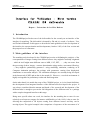
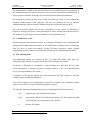
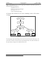
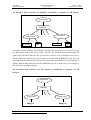
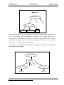
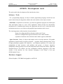
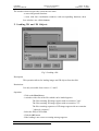
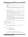
1
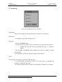
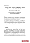
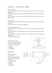
ESPRIT Project 9036
CHARM
Deliverable 8
Interface for Validation
Tasks
WP5
User Manual
and
Technical Manual
J. Blat
R. Mas
V. Martínez
J. Jaume
Universitat de les Illes Balears
CHARM
Report and Manual
Interface
Interface for Validation
First Version
J Blat - R Mas V Martínez - J Jaume
for Validation - First version
CHARM D8 deliverable
Report - Universitat de les Illes Balears
1. Introduction
The CHARM project fixed as one of the deliverables for the second year an interface of the
interface for matching. The deliverable is denoted by D8 and it is made of software, User
and Technical Manuals. In this paper we describe the main guidelines for the development of
the interface, the current situation and developments (October 1995) of the first version and
the perspectives of refinement.
2. Main guidelines of the interface
The matching tools developed in the CHARM project aim at facilitating the analysis of the
correspondence of images coming from different sources: they might be medically originated
- which in itself might mean different sources MRI, CAT, PET, … -; they can come from
the processing of these images - contour determination using snakes, movement following,
…; they might be synthetically generated - using modelling, animation, rendering as in
Computer Animation packages, but perhaps with parameters coming from biophysical
simulations or movement analysis. The validation techniques are currently being developed
in the framework of WP5 and are due in the month 36. However, a test bed environment is
highly envisageable for preliminary results and final integration.
On the other hand, it is outside the scope of the CHARM project, as in its formal definition,
the development of an integrated interface of the different tools developed in the project. It
was always considered that the amount and depth of the research and development of the
different tasks is enough to prevent the full integration of the different tools in a package
with a complex integrated interface at this stage.
Being more specific about our work, the interface for the matching has to cater for two
relatively novel aspects (compare for instance with Brodie et al eds, 1992); it has to cater for
allowing the comparison of 3D objects coming from different sources and they can be
moving objects. The typical example is the comparison of sequences of the movement of of
October 1995
2
CHARM
Report and Manual
Interface for Validation
First Version
J Blat - R Mas V Martínez - J Jaume
a shoulder-arm complex obtained from different sources - MRI, image processing,
synthetically generated sequence -.
In order to cope with these aspects, the interface has been developed based in SGI Inventor /
OpenInventor as these tools are becoming widely used because they are orientated towards
3D objects and its manipulation. This allows the integration of 3D functionalities with
relatively low cost. If in the future the needs of the project or its continuation require real
time performance (with the corresponding change in specifications), these tools will be able
to be integrated in a relatively easy way with Performer to achieve better performance. SGI
Inventor / OpenInventor was also chosen from the beginning of the project as
standard/common tool for the different teams involved in the CHARM project and enhanced
future integration of different parts of the project should be facilitated by this choice and the
work that has followed this rule.
Fig 1 A main view of the interface for the validation tasks
The visual design of the inteface is based on Inventor-like format and has been integrated
into an easy-to-use interface (fig.1). The Inventor system is becoming relatively widely
accepted and quite a few of the functionalities are integrated in the inteface - they are simple
to use and there is the advantage of re-using existing knowledge or being able to re-use it -.
October 1995
3
CHARM
Report and Manual
Interface for Validation
First Version
J Blat - R Mas V Martínez - J Jaume
The multiple windows allowed by the the windowing system appear usually hidden by the
window of the interface of the matching tools which takes control of the whole screen; this
unique window has four sub-window for allowing multiple sources (3) and a unified view
on the 4th window. This number of 4 appears reasonable for the use which is forecasted,
but modifications would be easy to introduce. This seems to be accepted as a model easier to
use for non-expert users (Shneiderman, 1992) who can concentrate on a simpler interface.
Similar principles are applied for the specific menus of the inteface which come as pop up
menus from buttons (Shneiderman, 1992).
Each of the 4 subwindows is organised - as mentioned - around the Inventor interface and
allows the representation of 3D models and the basic 3D interaction which allows Inventor.
As noted earlier each of the subwindows has some buttons allowing for pop-up menus
which are described in more detail later. In order to cater for the movement standard-looking
video controls have been introduced in each window while adding sliders allowing for a
more refined control of the sequences by frames/precise time.The interface is quite flexible,
allowing for the opening/viewing of independent 3D + time sources in 3 windows and their
integration in a 4th window.
While each of the subwindows can work independently, in order to develop the matching
tasks, guaranteeing the spatial and temporal coherence is an important requirement.
Currently the possibility of defining the spatial coherence by fixing a reference system in
each of the 3 independent subwindows which will be the common one is being explored.
This will allow for the possibility of coordinated 3D interaction in the different windows if
thus set by the user. In the same spirit, tools are being introduced for time synchronisation
of the sequences and its visualisation.
From the initial tests of the current developed version of the prototype it seems that the main
improvements for usability should go along the inclusion of the slicing interface provided by
UNG tools (which provide for spatial slicing), more automatisation of the matching - boths
spatial and temporal - and showing more information about the degree and level of matching.
3. Functionalities of the interface in more detail
The images obtained from MRI, CAT, or any other source will undergo the identification
process developed in workpackages WP1 and WP2 and the results obtained will have to be
compared to the results of the numerical simulation of muscular contraction or other sources.
In case of need, a call for a modification in the mechanical model or in the approximation
assumptions can take place. In a higher level, similar validation will be performed for the
simulation of the movements of more complex anatomical assemblies. The degree of
tolerable anatomical simplifications will be established.
October 1995
4
CHARM
Report and Manual
Interface for Validation
First Version
J Blat - R Mas V Martínez - J Jaume
The functionalities available in the interface allow an user-friendly supervision mechanism of
the validation process. We provide interactive tools to ensure synchronized visualizations of
image sequences obtained from both 3D reconstruction and mechanical simulations.
The interface also allows the user access to the tools that will ensure a correct spatial and
temporal synchronization of the sequences. The aim is to maximize the use of Inventor
standard methods to interact with the validation tools that will be developed in WP5.
The system provides mainly tools for the visualization, for the control of individual or
sequences of images and for the visual comparison of results coming from different sources.
We guarantee an easy plug-in of future automatic or semi-automatic tools.
3.1 Visualization tools
An important goal of the interface consists in a complete flexibility for the visualization and
management of either temporal sequences of 3D solid objects resulting of the reconstruction
from 2D slices or static and temporal varying 2D image sequences. Object oriented
programming eases the labor by providing data and operation encapsulating mechanisms.
3.2 File Management
Two-dimensional images are required to have iris image file format (rgb) and treedimensional input objects are supposed to be provided in Inventor file format.
A sequence of 2D images is visualized as a stack of images (see deliverable D2 for a more
precise description). A sequence of stacks of images results in a 3D+ time dimension that
can be correctly handled by the system.
A sequence of 3D objects represent the yet-reconstructed 3D solid volumes or the data
coming from the mechanical simulation.
A set of slice images can be transparently processed as a sequence for visualization control
purposes (each slice is a texture internally assigned to a plane).
The input file format are distinguished by the use of meaningful file name extensions:
•.rgb
represents pure rgb 2-dimensional images.
•.rgbs
represents a sequence of bi-dimensional images. The file contains the path
referencing the .rgb components of the sequence.
•.iv
inventor file format
October 1995
5
CHARM
Report and Manual
•.ivs
Interface for Validation
First Version
J Blat - R Mas V Martínez - J Jaume
sequence of inventor format files. The contents of the file is the indirect
addressing of the ordered individual components of the sequence.
Loaded images are discarded by its interactive deletion either individually or collectively. To
maintain the coherence in a stack of images, the last-in section is erased during the removal
of a single image.
The sequences are composed of frames and the frames can also be individually referenced
previously to their removal, the affected frame is the currently visualized one. The
visualization can be modified by using the corresponding video-controller (described later
on) or using the direct frame addressing mechanism.
For convenience, a global delete button is provided for a fast elimination of a full sequence.
3.3 Video Controller
A video controller-like set of panels provide the tools to command the display of the
sequences of images. An independent video controller is available for every viewer
excluding those displaying static bi-dimensional images.
2D and 3D sequences of images can be visualized using the video control panels. The
buttons present the same appearance as a conventional video reproducing system (see Fig.2
for a detailed view of each viewer):
•
All Backwards or rewind: defines the first frame in the sequence as the current
(and visualized) one.
•
All Forward: sets the last frame in the sequence to be the current frame.
•
Step Backwards: sets the previous frame as the current frame.
•
Step Forward: the following frame becomes the current one.
•
Play: a non-stop cycling display of the full sequence.
The user can modify the frame speed according to the requirements. A direct frame access is
also available to avoid the burden imposed by a sequential organization of the information.
For the visualization of 2D static images, the video control panels are automatically
deactivated, as they loose their sense.
October 1995
6
CHARM
Report and Manual
Interface for Validation
First Version
J Blat - R Mas V Martínez - J Jaume
Fig.2 Each viewer provides video control panels when displaying a sequence of images
3.4 Visual matching
A very subjective, non automatic mechanism is provided for an intuitive validation of the
reconstruction and simulation sequences: the visual matching (Fig.1).
A correspondence on the reference frames of the objects of both sequences, allow a first
basic frame-by-frame approximation to the validation tasks.
Up to three sequences can be simultaneously visualized in a common reference frame. The
number and identity of the affected sequences is described by means of a pop-up menu.
There is a dedicated window to deal with the superposed visualization of the compared
frames.
The resulting sequence can be itself manipulated using the corresponding video controller
with exactly the same characteristics than these previously mentioned.
3.5 Attributes
To ease the visual comparison of sequences, the lighting and objects attributes can be
interactively modified by the user. Inventor tools are used when possible to guarantee a high
level of portability and re-use of the code (Fig. 3)
October 1995
7
CHARM
Report and Manual
Interface for Validation
First Version
J Blat - R Mas V Martínez - J Jaume
Fig.3 Color tools
3.6 Synchronized Visualization
Although every viewer hold its own camera, they can all be synchronized to visually
compare the degree of tolerance of the matching. In the interface, only a visual validation
process is yet available. The extension to automatic or semi-automatic tools is part of the
scope of the WP5 activity.
3.7 Near-future functionalities
Funtionalities to be added to the interface follow:
•
Integration of the 2D and 3D snake modules, considered at the moment as
external independent programs.
•
Integration of the 3D reconstruction module. Source data coming from 3D snakes
segmentation or different source 2D images (MRI, CAT, PET, ...).
•
Integration of the techniques for an automatic or semi-automatic validation
mechanism on the 3D objects sequences.
Considering the need of a continuously growing number of functioanlities, the interface has
been designed encouraging the easy plug of new components.
4. Data structure
4.1 Global view
The visualization windows can be of up to four different types and for each of the windows
a hierarchical Inventor data structure is stored made of the images to be visualised at the
October 1995
8
CHARM
Report and Manual
Interface for Validation
First Version
J Blat - R Mas V Martínez - J Jaume
corresponding window. At the beginning, the windows belonged to a predefined Inventor
class SoXtExaminerViewer; later they have become a subclass of this class,
mySoXtExaminerViewer, in order to optimise them.
The nodes of the class SoXtExaminerViewer are nodes which allow the visualisation of
the scenes and the change of point of view for this visualisation, by manipulating the
parameters of the scene camera; these viewers were chosen because they provide an
importan flexibility in the scene manipulation. The user can visualize the 3D object or 2D
image loaded in each viewer and modify the camera parameters to see it from differents
points of view.
This class has been created especially for the development of the validation interface in order
to distinguish among the different types of visualisation which were specified and which
require a different type of processing.
The main nodes which make up theses structures are the following ones:
Nodes SoSeparator: these nodes allow for grouping other nodes; they are low cost and
help the hierachical structuring of the scene.
Nodes SoBlinker: these nodes are used to generate the sequence of images; they allow
the grouping of several objects with the property that at any moment only the visualization of
one of the sons is allowed. They contain the attributes allowing:
- Specifying the index of the son to be visualized (WhichChild).
- Generating cycles of visualization of the ( on ).
- Modifying the visualisation speed (speed).
Nodes SoMaterial: these nodes allow the specification of the material applied to the
object(s) and/or its(their) brother(s). A SoMaterial contains a series of attributes defining:
- The reflected color of an object depend on the ambient light in the scene.
- An object base color.
- Reflective quality of an object's highlights.
- Light that is produced by an object.
- Degree of shininess of an object´s surface.
- Degree of transparency of an object.
Nodes SoTexture: these nodes specify a 2D texture map to be applied to an object; they
have an attribute (filename) which specifies the name of the .rgb image to be used as a
texture map.
October 1995
9
CHARM
Report and Manual
Interface for Validation
First Version
J Blat - R Mas V Martínez - J Jaume
Nodes SoTransform: they are used to apply linear transforms to the objects; they have
fields allowing the specification of:
- Translation in X, Y, Z.
- Rotation in terms of axis and angle.
- Scale factor in X, Y, Z.
- Centre of rotation and scaling.
4.2 Inventor data structure for the viewers containing a stack of 2D sections
of images
SoSeparator
SoBlinker
SoSeparator
SoSeparator
SoTexture
...
File1
...
...
SoSeparator
SoTexture
File n
The SoSeparator objects that belong to the lowest levels in the tree have below them a file
and a texture. The files are Inventor objects representing 2D slices. The nodes SoTexture are
the .rgb sections or images to be visualised on the screen.
October 1995
10
CHARM
Report and Manual
Interface for Validation
First Version
J Blat - R Mas V Martínez - J Jaume
4.3 Inventor data structure for windows containing a sequence of 2D images
SoSeparator
SoBlinker
SoSeparator
SoTexture
...
...
...
SoSeparator
SoTexture
File1
File n
As in the previous structure, the SoSeparator objects that belong to the lowest levels in the
tree have below them a file and a texture. The files are Inventor objects representing 2D
planes. The nodes SoTexture are the .rgb sections or images to be visualised on the screen.
The key difference with the previous structure is that the node SoBlinker has got only one
son in the first case because there is only one scene in the viewer and there is no sequence of
images; while in the second case the node SoBlinker has got as many sons as 2D images as
the sequence to visualize contains.
4.4 Inventor data structure for the windows containing a sequence of 3 D
images
SoSeparator
SoBlinker
SoSeparator
Image 1
October 1995
...
...
...
SoSeparator
Image n
11
CHARM
Report and Manual
Interface for Validation
First Version
J Blat - R Mas V Martínez - J Jaume
Image i
SoSeparator
...
SoSeparator
SoMaterial SoTransform
...
File i1
For this data structure the files correspond to Inventor 3D objects and their extension has to
be .iv. This structure contains additionally a SoMaterial node through which color is
assigned to the whole sequence of images. It is the same color because of the coherence
towards the matching process in the validation: assigning a different color to the different
sequences/viewers helps in the visual comparison.
4.5 Inventor data structure for windows containing a sequence of 3D images
to perform the matching
SoSeparator
SoBlinker
SoSeparator
Image 1
October 1995
...
...
...
SoSeparator
Image n
12
CHARM
Report and Manual
Interface for Validation
First Version
J Blat - R Mas V Martínez - J Jaume
Image i
SoSeparator
SoSeparator
SoMaterial SoTransform
...
...
File i1
The matching structure is made of the composition of sequences of 3D images.
The node SoBlinker will have n sons where n is the number of sequences selected to
perform the matching, which will be less than or equal to 3, the maximum number of
sequences simultaneously viewed. The implementation is flexible enough to allow
incorporating more than 3 sequences.
The node SoMaterial indicates the color of each sequence maintaining the color taken in the
respective visualization window.
The node SoTransform performs a linear transformation to establish a common referenc
system for the different 3D sequences.
References
Brodie K W, Carpenter L A, Earnshaw R A, Gallop J R, Hubbold R J, Mumford A M,
Osland C D, Quarendon P (Editors): Scientific Visualization, Techniques and
Applications, Springer, Berlin - Heidelberg - New York, 1992.
Shneiderman B: Designing the User Inteface, Strategies for Effective HumanComputer Interaction, Second Edition, Addison-Wesley, Reading MA, 1992
Josie Werneke: The Inventor Mentor, Programming Object-Oriented 3 D
Graphics with Open Inventor, Release2, Addison Wesley Publishing Company, 1994.
OSF/MOTIF Programmer's Guide Revision 1.1, Prentice Hall 1991.
OSF/MOTIF Programmer's Reference Revision 1.1, Prentice Hall 1991.
October 1995
13
CHARM
Report and Manual
Interface for Validation
First Version
J Blat - R Mas V Martínez - J Jaume
James O. Coplien, Advanced C++ Programming styles and idioms, Addison
Wesley,1992.
Adrian Nye, Xlib Programming Manual , O'Reilly & Associates 1992.
October 1995
14
CHARM
Report and Manual
Interface for Validation
First Version
J Blat - R Mas V Martínez - J Jaume
ANNEX: Development tools
The tools used for the development of the interface have been
Software Tools
- C++ programming language, an object oriented programming language which has been
used for the facility for integration with the other tools which are also object oriented.
- OSF/Motif : Graphical User Interface, by which an application program can obtain input
from and display output to a user of the application. Motif provides the intermediary
mechanisms for communication between the application and the user.To both sides these
mechanisms apear as a set of objects with graphical representations on the screen.
The visual appearance of the interface is based on Motif:
- buttons for calling the different functions inside each Viewer
- buttors for calling different general functions for the whole interface
- separation of subzones into which the main window appears subdivided
- Open Inventor: library of objects and methos used to develop interactive 3D graphic
applications. Open Inventor is based on OpenGL - a graphics library allowing direct access
to high performance graphics SGI hardware - and comprises primitives for creation and
manipulation of data structures with attributes and groups of objects, interactive
manipulators allowing acting on scenes and components such as materials editors, lights and
ExaminerViewers. For instance, the four visualization windows appearing in the main
window of the interface are four elements belonging to this library of the type
SoXtExaminerViewer.
Hardware Support
Silicon Graphics, CPU R4000 and graphics card ELAN.
October 1995
15
CHARM
Report and Manual
Interface for Validation
First Version
Interface
J Blat - R Mas V Martínez - J Jaume
for Validation - First version
CHARM D8 deliverable
User Manual - Universitat de les Illes Balears
User Manual
It is convenient to read the report on the Interface before starting the reading of this manual
as the report contains the ideas implemented in this interface.
1. Start up mechanism
Execute the line command validate
Fig.1 A main view of the interface for the validation tasks
October 1995
16
CHARM
Report and Manual
Interface for Validation
First Version
J Blat - R Mas V Martínez - J Jaume
The window which occupies the screen has two zones
- a zone with general functions
- a zone with four visualization windows with corresponding functions; these
four windows are called viewers
2. Loading 2D and 3D Objects
Fig 2. Loading a file
Description
This operation allows for loading images and 3D objects from the disk.
Restrictions
It is only accessible from viewers 1, 2 and 3
Operation
- Click on the Read button
- A window with a list of the files which can be loaded appears.
The files containig 2D images appear with an extension ".rgb".
The files containig 3D images appear with an extension ".iv".
The files containig sequences of 2D images appear with an extension
".rgbs(rgb_sequnce)".
- Select the file(s) to be loaded.
- Click the OK button
- If the loading is not correct a warning message appears.
October 1995
17
CHARM
Report and Manual
Interface for Validation
First Version
J Blat - R Mas V Martínez - J Jaume
We use the following terminology:
- 3D window or viewer: containing a 3D image or a sequence of 3D images
loaded
- 2D window or viewer: containing a 2D image or a stack of 2D images
loaded
- Matching viewer: containing the superposition of sequences of 3D images;
this is the only viewer with a fixed position and functionalities in our interface.
Notes
- If the first file loaded is .iv and so are the following ones the result is a
sequence of images for visualisation
- If the first file loaded is .rgb and so are the following ones the result is a stack
of images for visualisation which are assumed to be sections or slices of a 3D
image for which the only operation available will be deletion.
- If the file loaded is .rgbs the result is a sequence of .rgb images for
visualisation. This sequence is visualised in the same way as a 3D objects
sequence. The file with the .rgbs extension must contain the names of the .rgb
files that make up the sequence.
- If the type of the second file which is loaded is different from the first one, the
file is not loaded and a warning message appears. In order to load into a viewer a
different type of images, the existing ones have to be completely deleted; this is
the way of changing the visualisation.
For each type of viewer the sequence or image loaded is stored in a different predefined
Inventor hierarchical structure.
3. Deleting an image or an object
Description
This operation eliminates a 2D image or an object of a 3D visualisation as well as
objects in a sequence for matching.
Operation
- Click on the Del button
- A window for confirmation appears.
click OK or CANCEL
Notes
The suppresion of the image depends on the type of visualisation.
In a viewer with a stack of 2D images the last image which has been loaded is
deleted.
October 1995
18
CHARM
Report and Manual
Interface for Validation
First Version
J Blat - R Mas V Martínez - J Jaume
In the case of a sequence of 2D or 3D images the object whose order is
referenced by the slider in the video panel is deleted.
4. Deleting the whole content of a viewer
Description
This operation eliminates all the images in a viewer.
Operation
- Click on the DellAll button in the corresponding viewer
- A window for confirmation appears.
click OK or CANCEL
5. Color
Fig.3 Color tools
Description
This operation assigns color to a sequence of 3D objects.
Restrictions
- It is available only in viewers containing a 3D sequence for visualization
- It is not available in the matching viewer
Operation
- Click on the Color button in the corresponding viewer
- Choose the set of color attributes desired in the materials editor appearing on
the screen.
October 1995
19
CHARM
Report and Manual
Interface for Validation
First Version
J Blat - R Mas V Martínez - J Jaume
6. Matching
Fig.4 Visual matching viewers selection
Description
This operation performs the superposition of sequences of 3D objects.
Restrictions
- It is available only in the matching viewer
Operation
- Click on the Match button
- A window with a list of the sequences of objects to be superimposed appears.
Remark that only the viewers containing this type of sequences
appear
- Click the OK or CANCEL button whether one wishes to continue or cancel
the operation
- In the matching viewer the sequences appear superimposed.
Notes
The automatic matching proceeds in the following way:
- for each sequence the center of mass of the first object is computed; the
reference is situated in this point.
- the following objects of the sequence are situated also with this new reference.
October 1995
20
CHARM
Report and Manual
Interface for Validation
First Version
J Blat - R Mas V Martínez - J Jaume
7. Vídeo
Fig.5 Video control panels are automatically deactivated when dealing with 2D static
images
Description
The video controller appears as a domestic video player controller and simulates
its behavior for the visualisation of sequences of 3D objects.It appears in the
lower left hand corner of the viewer
Restrictions
- This functionality is only available in viewers containing sequences of 3D
objects or in the matching viewer; the panel disappears when it is not necessary
Operation
The video controls implemented are:
- Rewind
- Previous
- Stop
- Next
- Fast Forward
October 1995
21
CHARM
Report and Manual
Interface for Validation
First Version
J Blat - R Mas V Martínez - J Jaume
8. Visualization speed
Description
Allows the modification of the speed of visualisation of a sequence of objects
Restrictions
This functionality is only available in viewers containing sequences of 3D
objects or in the matching viewer
Operation
Move the slider control with the label Sp to the desired value
The speed is measured in frames (images) per second and this is the
value indicated on the slider
9. Quick timer
Description
This operation allows the visualisation frame by frame.
Operation
-Move the slider control with the label Fr to the desired value of the frame
On the viewer the image with the order equal to the value indicated
on the slider appears.
October 1995
22
CHARM
Report and Manual
Interface for Validation
First Version
J Blat - R Mas V Martínez - J Jaume
10. Cameras
Fig.5 Camera selection
Description
This operation allows the synchronisation of two or three cameras corresponding
to the viewers.
Restrictions
- The cameras to be synchronized must belong to 3D viewers.
- At least two cameras must be selected
Operation
- Click on the Cameras button of the zone of general functions
- Select the cameras of the viewers to be synchronised
- Click the OK button if the selection is correct
11. Quitting the application
Description
Abandoning the interface environment
Operation
Click on the button Quit of the zone of general functions
October 1995
23
CHARM
Report and Manual
Interface for Validation
First Version
J Blat - R Mas V Martínez - J Jaume
ANNEX: Implementation Treatment of Viewer
Functions
Read
Treatment received depending on the file extension:
.rgb
The files having this extension are converted into a SoTexture node
applied to a plane. The relative position in the images stack is stored in a
SoTransform node at the same level of the objects hierarchy.
.rgbs
The file contains an indirect addressing through the name of each file
composing the sequence. The ordering of the references in the file is considered
as the ordering in the sequence. A SoSeparator will allow the incorporation of
the information to the three hierarchie.
.iv
Added to the hierarchy using a SoSeparator. A SoMaterial is also
aggregated to permit the user to modify the objects appearance for a better visual
discrimination.
.ivs
We use the same file format than a .rgbs file, the only difference being
the contents of the listed n component files. The resulting structure is equivalent
to the one used for n individually loaded .iv files.
Del
Depending on the kind of visulized data, the results of applying the delete function will
differ.
• If we are visualizing a stack of .rgb images, the last loaded section will be
removed, ie. the highest SoSeparator index, descendant of a SoBlinker
node.
• In case of a sequence of 2D, 3D or visual validation, the son n of the
corresponding SoBlinker structure will be erased. n denotes the order number
of the currently displayed image.
DelAll
Independently of the contents of the viewer, the aplication will erase all the descendats of the
SoBlinker node representing the visulized structure.
After a DelAll operation, the tree structure is reverted to its initial state:
October 1995
24
CHARM
Report and Manual
Interface for Validation
First Version
J Blat - R Mas V Martínez - J Jaume
SoSeparator
SoBlinker
Color
For editing the material attributes of the objects, primitive OpenInventor functions are used.
The SoMaterialEditor is invoked to change this attritute of the objects. The same
definition is applied to all the component of the viewer. Its objective not being the individual
identification of the components of the viewer but a visual help to be used in the visual
validation.
The SoMaterialEditor is automatically attached to the structure SoMaterial. Any
modification to the material attributes will directly be reflected in the corresponding
SoMaterial.
Match
This function is devoted to the superposition of the selected 3D image sequences.
The superposition takes place using a common reference system. A SoTransform contains
the information relative to the position of the elements and a SoMaterial replicates the
sequence color.
Video
The functions associated to the video player are Play, Rewind, FF, Stop, Previous and
Next. Let’s see the manipulation performed on the sequence of loaded data. The
manipulation takes place through the facilities provided by the class SoBlinker as follows:
Play
activates the SoBlinker on flag that stablish a visualization cycle of
their sons
Stop
deactivates the previous visualization.
Rewind Sets the current visualization frame to be the left-most SoBlinker
son. The whichChild field is conveniently modified.
FF
Sets the current visualization frame to be the right-most SoBlinker
son. The whichChild field is conveniently modified.
Next
The next son of the SoBlinker node is obtained and set as the
current whichChild field.
October 1995
25
CHARM
Report and Manual
Interface for Validation
First Version
J Blat - R Mas V Martínez - J Jaume
Previous The previous son of the SoBlinker node is obtained and set as the
current whichChild field.
Speed
Sets the speed field of the affected SoBlinker node.
QuickTimer Sets the whichChild field to be the slider-selected son of the node.
Cameras
The possibility of synchronizing the cameras of the selected viewers, allows a better visual
validation approach. The activation of the toggles representing the different cameras
produces the activation of a SoSensor entity to the viewers that will activate a callback
every time a camera is interactively modified. The callback handler takes care of the
computation of the orientation and translation variations of the moved camera and transmits
the resulting motion to the rest of selected synchronized cameras.
October 1995
26