1
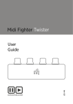
Operating Instructions
Type: VOGEL Order no.:
EC-Manufacturers Declaration (only valid for pump)
acc. to Machine Directive 2006/42/EG Appendix II B of European Parliament and Council of 17.05.2006.
Manufacturer: ITT Austria GmbH
A-2000 Stockerau, Ernst Vogel-Straße 2
Products:
Pumps of model WT
1)
1)
The mentioned products are intended for Installation into a machine / Assembly with other machines . Their putting
into operation is forbidden so long, till it is proven, that the machine, in which the pump shall be integrated,
corresponds with the regulations of the Machine Directive 2006/42/EG.
Used harmonised norms, especially
EN 809
EN ISO 12100 part 1
EN ISO 12100 part 2
Used national technical norms and specifications, especially
DIN 31001
The Declaration of the Manufacturer expires, when the pump is installed into units, where no declaration of
conformity, acc. to the Machine Directive 2006/42/EG, is existing.
Stockerau, 25.05.2009
1)
................................................................................................
Robert Salzbauer
Quality control
Strike out what´s not the case
EC-Declaration of Conformity on customer buyouts
If essential components of the unit (e.g. motors) are provided by the customer and only the assembly of
these components is made by ITT Austria, the whole conformity must be proved by the customer!
EC- Declaration of Conformity (only valid for units completely delivered by ITT Austria)
acc. to Machine Directive 2006/42/EG Appendix II A of European Parliament and Council of 17.05.2006.
Manufacturer: ITT Austria GmbH
A-2000 Stockerau, Ernst Vogel-Straße 2
Products:
Pumps of model WT
The mentioned products correspond with the regulations of the EC-Machine Directive 2006/42/EG.
Used harmonised norms, especially
EN 809
EN ISO 12100 part 1
EN ISO 12100 part 2
EN 60204 part 1
Used national technical norms and specifications, especially
DIN 31001
For Declaration of Conformity of appliances and / or components (e.g. motors) used with the unit, refer to
attachments. The Declaration of Conformity expires, when the pump is installed into units, where no Declaration of
Conformity, acc. to Machine Directive 2006/42/EG, is existing.
Stockerau, 25.05.2009
................................................................................................
Robert Salzbauer
Quality control
Operating instructions
Table of Contents
Data Sheet
1. General ............................................................................................ page 3
1.1 Foreword
1.2 Guarantee
1.3 Safety regulations
1.4 Safety instructions
Dangers of not following safety instructions
Safety instructions for the operator
Speed, Pressure, Temperature
NPSH
Sealing, Flushing, Cooling,
Minimum flows
Protection against running dry
Back flow
2. Description ...................................................................................... page 7
2.1 Model
2.2 Shaft Sealing
2.3 Bearings and Lubrication
3. Transport, Handling, Storage ....................................................... page 7
3.1 Transport, Handling
3.2 Storage
4. Installation, Operation ................................................................... page 9
4.1 Preparing for installation
4.2 Assembly and installation the pump
4.3 Installation and Alignement of Coupling
Permitted displacement for flexible couplings
4.4 Connecting the pipes to the pump
Discharge pipe
Auxiliary pipes
4.5 Electrical connection
4.6 Starting up
Starting up for the firts time
Restarting
4.7 Operation and Monitoring
Permitted number of starts
4.8 Shutting down
4.9 Dismantling
5. Maintenance, Servicing .................................................................. page 13
Stuffing boxes
Mechanical seals
Oil lubrication
Couplings
Cleaning the pump
WT 101/3
1
Operating instructions
6. Longer periods of non-operation .................................................. page 15
6.1 Drained pumps
6.2 Filled pumps
7. Faults - Causes and Solutions ........................................................ page 16
8. Repairs ............................................................................................. page 19
9. Spare parts, spare pumps .............................................................. page 19
9.1 Spare parts
Ordering spare parts
9.2 Stand-by pumps
10. Plant Manager List ....................................................................... page 20
11. Log Book ........................................................................................ page 21
Appendix
WT 101/3
2
Operating instructions
1. General
1.1 Foreword
This product complies with the safety requirements of EC Machinery Directive 2006/42/EC.
The staff employed on installation, operation, inspection and maintenance must be
able to prove that they know about the relevant accident prevention regulations and
that they are suitably qualified for this work. If staff do not have the relevant
knowledge, they should be provided with suitable instruction.
The operating safety of the pumps or units (i.e. pump plus motor) supplied is only guaranteed if
these are used in accordance with the provisions given in the attached Data Sheet and/or Point 4 in
„Installation and Operation“.
The operator is responsible for following the instructions and complying with the safety
requirements given in these Operating instructions.
Smooth operation of the pump or pump unit can only be achieved if installation and maintenance
are carried out carefully in accordance with the rules generally applied in the field of engineering
and electrical engineering.
If not all the information can be found in these Operating instructions, please contact us.
The manufacturer takes no responsibility for the pump or pump unit if the Operating instructions
are not followed.
These Operating instructions should be kept in a safe place for future use.
If this pump or pump unit is handed on to any third party, it is essential that these Operating
instructions and the operating conditions and working limits given in the Confirmation of Order
are also passed on in full.
These Operating instructions do not take into account all design details and variants nor all the
possible chance occurrences and events which might happen during installation, operation and
maintenance.
Alterations or changes to the machine are only permitted by agreement with the manufacturer.
Original spare parts and accessories authorised by the manufacturer should be used for greater
safety. We bear no responsibility for the consequences of using other parts.
We retain all copyright in these Operating instructions; they are intended only for personal use by
the owner of the pump or the pump unit. The Operating instructions contain technical instructions
and drawings which may not, as a whole or in part, be reproduced, distributed or used in any
unauthorised way for competitive purposes or passed on to others.
1.2 Guarantee
The guarantee is given in accordance with our Conditions of Delivery and/or the confirmation of
order.
Repair work during the guarantee period may only be carried out by us, or subject to our written
approval. Otherwise the guarantee ceases to apply.
Longer-term guarantees basically only cover correct handling and use of the specified material.
The guarantee shall not cover natural wear and tear and all parts subject to wear, such as
impellers, shaft sealings, shafts, shaft sleeves, bearings, wear rings etc., or damage caused by
transport or improper handling.
WT 101/3
3
Operating instructions
In order for the guarantee to apply, it is essential that the pump or pump unit is used in accordance
with the operating conditions given on the type plate, confirmation of order and in the Data Sheet.
This applies particularly for the endurance of the materials and smooth running of the pump and
shaft sealing.
If one or more aspects of the actual operating conditions are different, we should be asked to
confirm in writing that the pump is suitable.
1.3 Safety regulations
These Operating instructions contain important instructions which must be followed when the
pump is assembled and commissioned and during operating and maintenance. For this reason,
these Operating instructions must be read by the skilled staff responsible and/or by the operator of
the plant before it is installed and commissioned, and they must be left permanently ready to hand
at the place where the pump or pump unit is in use. The operator must ensure that the contents of
the Operating instructions are fully understood by the staff. The operator must confirm this by
signing the „Plant Manager List“ (see Point 10). These Operating instructions do not refer to the
General Regulations on Accident Prevention or local safety and/or operating regulations. The
operator is responsible for complying with these (if necessary by calling in additional installation
staff).
The safety instructions contained in these Operating instructions have the following special safety
markings as specified in DIN 4844:
Warning against personal accidents which could occur if the safety instructions
given in this part of the Operating instructions are not followed.
Warning against dangerous electrical voltage.
Please
note
Warning against possible damage to property or the environment.
It is absolutely essential that safety information affixed directly to the pump or pump unit is
followed and maintained so that it is always easily legible.
1.4 Safety instructions
Dangers of not following safety instructions
Failure to follow the safety instructions can result in the following, for example:
• People being at risk because of electrical, mechanical and chemical factors.
• Important functions of the pump or pump unit failing.
• Dangers to the environment as a result of dangerous substances leaking out.
WT 101/3
4
Operating instructions
Safety instructions for the operator
• Depending on the operating conditions, wear and tear, corrosion or age will limit the working
life of the pump/pump unit, and its specified characteristics. The operator must ensure that
regular inspection and maintenance are carried out so that all parts are replaced in good time
which would otherwise endanger the safe operation of the system. If abnormal operation or any
damage are observed, the pump must cease operation immediately.
• If the breakdown or failure of any system or unit could lead to people being hurt or property
being damaged, such system or unit must be provided with alarm devices and/or spare modules,
and they should be tested regularly to ensure that they function properly.
• If there is any risk of injury from hot or cold machine parts, these parts must be protected against
contact by the user, or suitable warning signs must be affixed.
• Contact protection on moving parts (e.g. coupling guards) must not be removed from systems
that are in operation.
• If dangerous media (e.g. explosive, toxic, hot) leak out (e.g. from shaft seals), these must be
directed away so that there is no danger to people or the environment. The provisions of the law
must be observed.
• Measures should be taken to exclude any danger from electricity (e.g. by complying with the
local regulations on electrical equipment). If work is carried out on live electrical components,
they should be unplugged from the mains or the main switch turned off and fuse unscrewed. A
motor protection switch is to be provided.
• Basically, all work on the pump or pump unit should only be carried out when the pump is
stationary and not under pressure. All parts must be allowed to return to ambient temperature.
Make sure that no-one can start the motor during such work. It is essential that the procedure for
stopping the system described in the Operating instructions is observed. Pumps or pump systems
that carry media that are dangerous to health must be decontaminated before being taken apart.
Safety Data Sheets for the various liquids handled. Immediately the work has been completed,
all safety and protective devices must be replaced or restarted.
• Under EC Machinery Directives, every machine must be fitted with one or more emergency
command devices by which situations which represent an immediate danger or which could later
be dangerous can be avoided. This does not include machines in which the emergency switches
cannot reduce the danger, either because they do not reduce the time required to stop the
machine or because the do not allow the measures required by the danger to be taken. This
emergency switch must:
have controls that are clearly marked, easy to see and within easy reach;
stop the dangerous movement as quickly as possible without causing any additional danger;
trigger any specified safety movements or allow these to be started up.
If the emergency command device is no longer operated after an emergency „off“ switch has
been triggered, this must be maintained by blocking the emergency command device until it is
released again. It should not be possible to block the device without this triggering an emergency
„off“ switch. It should only be possible to release the device through an appropriate action; this
release should not start the machine up again - it should only make it possible to start it up again.
• If the power supply is interrupted or restored after being interrupted or if it is changed in any
other way, this should not cause any danger (e.g. pressure surges).
WT 101/3
5
Operating instructions
Speed, Pressure, Temperature
Suitable safety measures must be taken at the plant to ensure that the speed, pressure and
temperature of the pump and the shaft sealing do not exceed the limit values given in the Data
Sheet. The given admission pressures (system pressures) must also be sufficiently high.
In addition, the pump must be protected against pressure surges such as can be caused by
switching off the plant quickly (e.g. by non-return valve on the pressure side, flywheel, air vessel).
NPSH
When entering the impeller, the liquid being handled must have a minimum pressure NPSH to
prevent cavitation or breaking off of flow. This requirement is met if the unit NPSH value
(NPSHA) is well above the pump NPSH value (NPSHR) under all operating conditions.
Attention must be paid to the NPSH value in particular when liquids close to boiling point are
being handled. If the value falls below the pump NPSH value, this can lead to damage resulting
from cavitation or serious damage from overheating.
The NPSHR for each pump type is given in the sheets of characteristic curves. We can supply
leaflets for calculation of NPSH values on request.
Sealing, Flushing, Cooling
Suitable facilities for the regulation and monitoring of sealing, flushing or cooling are to be
provided.
When handling dangerous liquids or if temperatures are high, care should be taken to ensure that
the pump ceases operating if the sealing, flushing or cooling system fails.
Sealing, flushing and cooling systems must always be operational before the pump is started up.
They should not be taken out of operation until the pump has stopped, provided that the nature of
the operation allows this at all.
Minimum flows
If the pump is started against a closed pressure line valve, it should be noted that the power taken
up by the pump is transmitted to the liquid handled in the form of heat. This can cause the liquid
to heat up excessively within a relatively short time, which will then cause damage to the pump's
internal fittings. After the pump has reached operating speed, the discharge valve should therefore
be opened as quickly as possible. If operating conditions mean that Q = Ø is unavoidable, or if hot
water is circulating, a free flow non-return valve, or, on smaller systems, a by-pass pipe, should be
provided. We should be pleased to advise on determining the minimum flow or designing the bypass line.
Protection against running dry
Vertical shaft pumps may only be taken into operation when the pump part is flooded by the
pumping medium.
If this is not the case sliding components (e.g. plain bearings) or parts which rotate around narrow
cracks (e.g. impellers) can be destroyed.
Back flow
In systems where pumps are operating in closed circuits under pressure (gas cushions, steam
pressure), the pressure of the gas cushion must not be reduced via the pump, since the back flow
speed may be much higher than the operating speed, which would destroy the unit.
WT 101/3
6
Operating instructions
2. Description
2.1 Model
Single stage radial volute casing pumps with closed impeller in vertical shaft version with drive
above the shaft cover (plate). Pumping medium pumped through the shaft cover by the pressure
line.
Please see the Data sheet and Appendices for the sectional drawings and index of parts for each
pump.
2.2 Shaft Sealing
There are basically two methods of shaft sealing: the stuffing box and the mechanical seal. You
will find on the Data sheet the type of shaft sealing on your pump.
Please
note
You will find more information on stuffing boxes and mechanical seals, and the
risks of accidents that these may involve, under Point 4.6 „Operation and
Monitoring“ and in Point 5 „Maintenance and Repairs“.
2.3 Bearings and Lubrication
Bearing block (oil lubrication)
Bearings are a pair of single row angular contact ball bearings in X disposition. Oil lubricated.
Bearing type: 7313 BG
Types of oil see in attached lubricant chart T 011.
Pump part and shaft
Bearing and guiding of the shafts is made by 4 liquid lubricated slide bearings consisiting of
bearing bush and bearing sleeve.
Lubrication of slide bearings is made by feeding with raw water. Connection of the upper side of
the base plate.
Raw water quality:
solids < 100 µm
quantity 5 l/min per bearing unit
pressure approx. 1-2 bar
3. Transport, Handling, Storage
3.1 Transport, Handling
• Check the pump/pump unit immediately upon delivery/receipt of despatch for damage or
missing parts.
• The pump/pump unit must be transported carefully and by competent personnel. Avoid serious
impacts.
• Keep the pump/pump unit in the same position in which it was supplied from the factory. Take
note of the instructions on the packaging.
WT 101/3
7
Operating instructions
• Intake and discharge side of pump must remain closed with protective caps or covers during
transport and storage.
Please
note
Dispose of all packing materials in accordance with local regulations.
• Lifting devices (e.g. fork-lift truck, crane, crane device, pulleys, etc.) must be sufficiently strong.
The weight of the pump/pump unit is given in the Data Sheet.
• The pump/pump unit may only be lifted by solid points such as the casing, flanges or frame. The
following illustration shows the correct method of carrying by crane.
Please
note
Ropes, chains and other lifting aids must not be fixed to the end of shafts or the
ring loops of the motor.
Do not stand underneath suspended loads; take note of the general regulations on
prevention of accidents.
The pump/pump unit must be secured against tipping over and slipping until it has
been fixed in its final location.
3.2 Storage
Pumps or pump units that are stored for a long time before use must be protected against moisture,
vibrations and dirt (e.g. by wrapping in oil paper or plastic sheeting). Pumps must basically be
stored in a place where they are protected from the weather, e.g. under cover. During this time, all
WT 101/3
8
Operating instructions
suction and discharge branches and all other intakes and outlets must be closed with dummy
flanges or plugs.
4. Installation, Operation
4.1 Preparing for installation
Before the pump is installed the shaft opening must be constructed as shown in the binding
dimensional drawing.
The support area for the pump must be constructed in such a way that it can withstand all stress
which may arise during operations
Please
note
Sufficient space must be provided for maintenance and repair work, especially for
replacing the drive motor or the complete pump unit.
The motor fan must be able to take in enough cool air, and the intake grille must
therefore be at least 10 cm away from any wall, etc.
If vibrations to nearby parts are to be avoided, a stable frame is required between the plate (380/A)
and the shaft cover which should stand on a suitable vibration isolating base (structure-borne noise
absorning plates or rubber metal connection).
Please
note
The size of these insulating panels will vary, depending on circumstances, and
should therefore be determined by an experienced specialist.
4.2 Assembly and installation of pump
• Before installing the pump remove coarse impurities from the pump shaft.
• Remove protective caps or covers from the pump openings.
• If transport and installation conditions allow, the pumps are delivered preassembled. In this case
the pump can be installed in the shaft opening without further assembly work and the plate
(380/A) screwed to the shaft cover.
• If the pumps are delivered disassembled in components and parts, assembly must be carried out
in accordance with the instructions for Assembly contained in the Appendix.
4.3 Installation and Alignment of Coupling
Make sure that nobody can start the motor during work on the coupling.
According to Accident Prevention Regulations, the pump unit may only be
operated when the coupling guard is mounted.
With pump units (i.e. pump with motor) supplied complete, no work is required on the coupling
before use.
WT 101/3
9
Operating instructions
If the pump unit is not completely assembled until it reaches its place of use and no separate
operating instructions have been supplied by the manufacturer, you should proceed according to
the following points:
• Before starting installation, carefully clean shaft ends and coupling components.
• Pull coupling onto shaft end, do not hit. The coupling may be heated beforehand in an oil bath to
approx. 100° C (pulling on is then easier). Remove rubber packs from coupling section first.
• Observe axial distance between two couplings.
• Secure coupling hubs against axial sliding using a pin screw.
• Mount coupling guard.
Permitted displacement for flexible couplings
Design ..GK, A..FK(KK), B..FK(KK), H..FK(KK)
4.4 Connecting the pipes to the pump
Discharge pipe
• Basically the pressure line should be constructed so that the pump is subject to as few forces as
possible.
• When laying the pipes, make sure that the pump is accessible for maintenance and installation.
• The pipeworks are to be arranged so that the whole pump can be pulled (extension piece).
Auxiliary pipes
The raw water feeding to the bearing lubrication as well as eventually existing sealing-, flushingor cooling lines have to be switched on. Please consult the Data Sheet to see which pipes,
pressures and quantities are necessary. Safety installations required by the plant are not taken into
account.
Please
note
Point 1.4, „Sealing, Flushing, Cooling“ must be observed as regards regulation and
monitoring.
It is recommended that a pipeline is installed to take off any leakage from the shaft seal.
4.5 Electrical connection
Electrical connection work may only be carried out by an authorised professional.
The rules and regulations valid for electrical technology, especially those
WT 101/3
10
Operating instructions
concerned with safety measures, must be observed. The regulations of the national power supply
companies operating in that area must also be observed.
Before starting work, check that the information on the motor rating plate is the same as the local
mains network. The power supply cable of the coupled drive motor must be connected up in
accordance with the wiring diagram produced by the motor manufacturer.
A protective motor switch is to be provided.
Please
note
The direction of rotation should only be checked when the pump is full. Dry
running will cause damage to the pump.
4.6 Starting up
The plant may only be started up by people who are familiar with the local safety
regulations and with these Operating instructions (especially with the safety
regulations and safety instructions given here).
In order to be able to observe and monitor the shaft sealing, no protective covering
is provided in this area. If the pump is runnin, particular care should therefore be
taken (watch out for long hair, loose pieces of clothing etc.).
Starting up for the first time
• Fill in oil at the oil-filling-screw (FS). Oil quality see attached lubricant chart T 011. Height of
filling: see mark at the oil level indicator (ÖA).
• The whole of the pump part must be flooded with the pumping medium when operations are
started.
• Turn pump unit once again by hand and check that it moves smoothly and evenly.
• Switch on raw water supply as well as eventually existing sealing-, flushing- or cooling lines.
• Check that coupling guard is installed and that all safety devices are operational.
• Set discharge side slide valve to approx. 25% of rated flow quantity. With pumps with a
discharge branch rated width less than 200, the slide valve can remain closed when starting up
(see also Point 1.4 „Minimum quantities“).
• Check direction of rotation by switching on and off briefly. It must be the same as the directional
arrow on the bearing frame.
• Start drive device.
• As soon as it reaches normal operating speed, open discharge valve immediately and adjust the
required operating point.
• Packing:
Packings need leakage to operate perfectly (liquid being handled to drip out).
To start with, set the leakage rate fairly high. During the first few hours of operation, slowly
reduce the leakage rate as the pump is running by gradually tightening the packing gland (see
Item „69“ and „M2“ in the sectional drawing). The guideline value is around 10 drops/minute.
Please
note
WT 101/3
Packings that run dry will harden and then destroy the shaft sleeve and/or the
shaft.
11
Operating instructions
Restarting
Basically, the same procedure should be followed as for starting up for the first time. However,
there is no need to check the direction of rotation and the accessibility of the pump unit.
Make sure that the pump keeps filled with liquid after stopping and that eventually existing
sealing-, flushing- or cooling lines are kept switched on or switch off automatically at putting into
operation.
4.7 Operation and Monitoring
Be particularly careful not to touch hot machine parts and when working in the
unprotected shaft seal area. Remember that automatically controlled systems may
switch themselves on suddenly at any time.
Suitable warning signs should be affixed.
Please
note
Regular monitoring and maintenance will extend the life of your pump or pump
system.
• You must observe the area of application given on the Data Sheet.
• Do not exceed the output given on the motor rating plate.
• Avoid dry running, running against closed discharge valves or operation whilst the liquid
handled is in the vapour phase.
• Avoid sudden changes in temperature (temperature shocks).
• The pump and motor should run evenly and without vibrations; check at least once a week.
• The bearing temperature (measured on the bearing frame) should be max. 50° C above ambient
temperature and should not exceed 90° C; check at least once a week.
• Check leakage rate from packings at least once a week (see Point 4.5 „Packings“).
• Check the regulating and monitoring facilities of any sealing, flushing or cooling systems once a
week to ensure that they function properly. Outgoing cool water should be body temperature.
• Pumps which are exposed to corrosive chemicals or to wear through abrasion must be inspected
periodically for corrosion or wear and tear. The first inspection should be carried out after six
months. All further inspection intervals should be determined on the basis of the state of the
pump.
Permitted number of starts
Do not exceed the pump's permitted number of starts - see diagram.
WT 101/3
12
Operating instructions
With
electric
motors,
the
permitted number of starts is
given in the attached motor
operating instructions.
If two different figures are given,
the lower figure is valid.
motor power P [kW]
4.8 Shutting down
• Close slide valve in discharge pipe. This is not necessary if there is a spring-loaded non-return
valve.
• Switch of motor (make sure it runs down quietly).
• Close auxiliary systems. Do not shut down cooling system until pump has cooled down.
• If there is any risk of freezing, empty pump, cooling areas and pipes completely.
If the pump also remains under operating conditions (pressure and temperature) when stationary:
leave all sealing, flushing and cooling systems switched on.
The shaft sealing must remain sealed if there is a risk of air being sucked in (in the event of supply
from vacuum systems or parallel operation with shared suction pipe).
4.9 Dismantling
The operator's or manufacturer's fitters should be informed as to the nature of the
liquid handled. In the case of pumps handling dangerous liquids, the liquid
handled should be disposed of by environmentally acceptable means before the
pump is dismantled.
• Before starting to disassemble the pump unit make sure that it cannot be switched on again.
• The pump casing must be depressurised and empty.
• All valves in the discharge pipe must be closed.
• All components must have cooled down to ambient temperature.
5. Maintenance, Servicing
Work should only be carried out on the pump or pump unit when it is not in
operation. You must observe Point 1.4 „Safety instructions“.
WT 101/3
13
Operating instructions
Please
note
Maintenance and servicing work must only be carried out by trained, experienced
staff who are familiar with the contents of these Operating instructions, or by the
Manufacturer's own service staff. The work carried out must be duly entered in the
„Log Book“ (see Point 11) and confirmed by being signed.
Stuffing boxes
Stuffing boxes require constant maintenance (see also Point 4.6, „Starting up for the first time“). If
the leakage rate can no longer be set correctly, the packing is worn out and must be replaced in
good time (increased wear on shaft). With new packings, only tighten the packing gland slightly to
start with (heavy leakage). Always fit packings so that joints are at 90° to each other (see
drawing). After running-in time, tighten the packing gland slowly and evenly during operation
until there is only slight leakage. Do not allow to run dry.
Position of packing units
in relation to each other
Radial fitting of packing rings
right
wrong
Because of the risk of accidents, addition of packing to pumps during operation or
at operating pressure or temperature is strictly forbidden.
Mechanical seals
Mechanical seals are maintenance-free almost almost leak-proof. Pumps with mechanical seals may
only be operated when completely full, since dry running will destroy the mechanical seal.
The mechanical seal space must always be filled with liquid when the pump is in operation. If the
liquid being handled drips out at the mechanical seal, it is damaged and must be replaced.
When fitting the mechanical seals, make sure that everything is clean. The slide faces in particular
must be clean and undamaged. Apply a thin layer of water, soapy water or liquid soap to the
sliding faces to make it easier to slide the rotating units onto the shaft or when inserting the
counterrings. Only use mineral oils or grease if it is absolutely certain that the elastomers are oilresistant. Leave sliding surface dry, do not lubricate. Do not force the elastomeric elements over
sharp edges, use fitting sleeves if necessary. Push bellow-type mechanical seals so that the bellow
is pushed together and not stretched.
Before opening the pump, it is essential that you note Point 1.4 „Safety
instructions“, Point 4.9 „Dismantling“ and Point 8 „Repairs“.
WT 101/3
14
Operating instructions
Oil lubrication
• After the first 200 operating hours, drain oil (oil drain „AS“) and flush with fresh oil. Close oil
drain „AS“ again.
• Fill in fresh oil at the oil-filling-screw (FS). See filling level at the mark on the oil level indicator
(ÖA). Oil quality see attached lubricant chart T 011.
• Change oil every 6 months or every year (depends on humidity of air).
• If the pumps stands still for longer time the oil may be changed only after 2 years.
Please
note
Old oil should be disposed of in accordance with the valid national environmental
regulations.
Couplings
Check the play in the coupling components regularly approx. every 1000 operating hours and
replace worn elements.
Cleaning the pump
Dirt on the outside of the pump has an adverse effect on transmission of heat. The pump should
therefore be cleaned with water at regular intervals (depending on the degree of dirt).
Please
note
The pump should not be cleaned with pressurised water - water will get into the
bearings
6. Longer periods of non-operation
Please
note
After long stationary periods, packings may have hardened; these must be replaced
before start-up. When starting up, follow the instructions for starting up for the
first time (see Point 4.6)!
6.1 Drained pumps
• Turn by hand at least 1x week (do not switch on because of dry running).
• If necessary, unblock by tapping gently on the shaft in axial direction.
• Replace bearing oil after 2 years.
6.2 Filled pumps
• Switch stand-by pumps on and immediately off again once a week.
• If the stand-by pump is at operating pressure and temperature:
leave all sealing, flushing and cooling systems switched on.
• Replace bearing oil after 2 years.
• Do not tighten the stuffing box until there are no leaks.
WT 101/3
15
Operating instructions
7. Faults - Causes and Solutions
The following notes on causes of faults and how to repair them are intended as an aid to
recognising the problem. The manufacturer's Customer Service Department is available to help
repair faults that the operator cannot or does not want to repair. If the operator repairs or changes
the pump, the design data on the Data Sheet and Points 1.2-1.4 of these Operating instructions
should be particularly taken into account. If necessary, the written agreement of the manufacturer
must be obtained.
Faults
Discharge too low
Discharge stops after a time
Head too low
Head too high
Drive mechanism overloaded
Pump not running quietly
Temperature in the pump too high
Temperature in the shaft sealing too high
Temperature at the bearing too high
Pump leaking
Leakage rate at shaft sealing too high
Code no. for cause and method of repair
1, 4, 6, 7, 8, 9, 10, 11, 12, 13, 14, 15, 17
8, 10, 11, 12, 28
2, 4, 6, 7, 8, 9, 10, 11, 12, 13, 14, 15, 28, 32
3, 5, 32
2, 3, 5, 15, 16, 24, 25
7, 10, 14, 22, 23, 24, 27, 28, 31
7, 10, 28
17, 18, 19, 20, 21
2, 14, 23, 24, 27, 29, 30
24, 26
16, 19, 20, 21, 22, 24
Meaning of code number for cause and method of repair
1.
Back-pressure too high
• open discharge valve further
• reduce resistance in discharge pipe (e.g. clean filter if necessary)
• use larger impeller (note available motor power)
2.
Back-pressure too low, discharge too low
• throttle discharge valve
3.
Speed too high
• reduce speed
• compare speed of motor with specified pump speed (rating plate)
• when adjusting speed (frequency transformer) check reference value setting
4.
Speed too low
• increase speed (check available motor power)
• compare speed of motor with specified pump speed (rating plate)
• when adjusting speed (frequency transformer) check reference value settings
5.
Impeller diameter too large
• use smaller impeller
WT 101/3
16
Operating instructions
6.
Impeller diameter too small
• use larger impeller (check available motor power)
7.
Pump and/or pipes not completely filled with liquid
• fill
• vent
8.
Pump blocked
• clean
9.
Air pocket in pipeline
• vent
• improve course of pipe
10. NPSH of system too small
• increase liquid level
11. Air being sucked in
• increase liquid level
12. Air being sucked in through shaft sealing
• clean sealing pipe
• increase sealing pressure
• replace shaft sealing
13. Direction of rotation is wrong
• swap over two phases of power supply (to be done by a specialist electrician)
14. Inner components suffering from wear
• replace worn parts
15. Density and/or viscosity of liquid handled is too high
• seek assistance
16. Stuffing box not straight
• tighten evenly
17. Stuffing box too tight
• loosen
18. Shaft sealing worn
• tighten packing
• replace packing and/or mechanical seal
• check sealing, flushing and cooling pipes (pressure)
• avoid dry running
19. Lines and roughness on shaft or shaft sleeve
WT 101/3
17
Operating instructions
• replace parts
20. Unsuitable packing material
• use suitable material (check shaft or shaft sleeve for damage beforehand)
21. Deposits on mechanical seal
• clean
• replace mechanical seal if necessary
• if necessary provide additional rinsing or quench
22. Impeller out of balance
• remove blocks/deposits
• replace if broken or unevenly worn
• check shafts to ensure that they are running true
23. Distance between couplings too small
• change
24. Forces in pipeline too high (pump unit under strain)
• change (support pipes, use compensators, etc.)
25. Electricity supply not right
• check voltage of all phases (2-phase running)
• check cable connections
• check fuses
26. Sealing insufficient
• tighten screws
• replace sealing
27. Bearing damaged
• replace
• check lubricant and bearing space for pollutants (rinse oil area)
28. Discharge too small
• increase minimum amount carried (open slide valves, bypass)
29. Discharge too high
• reduce amount carried (throttle slide valve)
30. Relief fittings insufficient
• clean relief openings in impeller
• replace worn parts (impeller, split rings)
31. System-related vibrations (resonance)
• seek assistance
WT 101/3
18
Operating instructions
32. Manometer indicator wrong
• check manometer
• get rid of blockages
• put manometer in suitable place (no flow distortion or burbling)
8. Repairs
Repairs to the pump or pump system may only be carried out by authorised skilled
personnel or by the manufacturer's specialist staff.
We would be pleased to send you detailed repair instructions on request. Trained Customer
Service engineers are available to assist with installation and repair work on request.
When removing the pump, you must comply with Point 1.4 „Safety instructions“, Point 3.1
„Transport, Handling“ and Point 4.9 „Dismantling“.
9. Spare parts, spare pumps
9.1 Spare parts
Spare parts should be selected to last for two-years continuous operation.
If no other guidelines are applicable, we recommend that you stock the number of parts listed
below (in accordance with VDMA 24296).
2
spare parts
impeller
wear plate
shaft with key and shaft screws/nuts
plain bearing
bearing bush
sets
running sleeve
sets
shaft sleeve
sets
mechanical seal
packing rings
joints
sets
rubber packing for coupling
sets
Please
note
WT 101/3
1
1
1
1
2
2
2
2
16
4
2
Number of pumps (incl. stand-by pumps)
3
4
5
6/7
8/9 10/more
number of spare parts
1
1
1
1
2
2
3
3
16
6
3
1
1
2
2
2
2
4
4
24
8
4
2
2
2
2
3
3
5
5
24
8
5
2
2
2
3
3
3
6
6
24
9
6
3
3
3
4
4
4
7
7
32
10
7
30%
30%
30%
50%
50%
50%
50%
90%
40%
100%
100%
To ensure optimum availability, we recommend that suitable quantities of spare
parts are held in stock, especially if these are made from special materials and in
the case of mechanical seals, because of the longer delivery times.
19
Operating instructions
Ordering spare parts
When ordering spare parts, please supply the following information:
• Type: ________________________
Order no.: ________________________________
• Part designation ______________________ in sectional drawing ________________________
All the information is given in the Data Sheet and the relevant sectional drawing.
9.2 Stand-by pumps
It is essential that a sufficient number of stand-by pumps are kept ready for use in
plants where failure of a pump could endanger human life or cause damage to
property or high costs. Regular checks should be carried out to ensure that such
pumps are always ready for use (see Point 6.2).
10. Plant Manager List
Each plant manager should sign below to confirm that he has received, read and understood these
Operating instructions. He undertakes to follow the instructions conscientiously. If these
instructions are not followed, the manufacturer's guarantee and liability shall cease to apply.
Name:
Date:
Signature:
WT 101/3
20
Operating instructions
11. Log Book
Each plant operator shall duly enter all maintenance and service work that has been carried out,
and shall see that the person responsible confirms such work by signing below.
maintenance work:
Date:
Signature
Confirmed by
Plant operator
person responsible:
WT 101/3
21
Operating instructions
WT 101/3
22