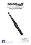
1
USER MANUAL
TRAINER X-STREAM
Dimensions
All dimensions are in millimeters
985
740
735
©2006-12009 MSS Professional A/S. All rights reserved. No part of this manual may be
reproduced, in any form or by any means, without permission in writing from MSS
Professional A/S, Denmark. Information subject to change without notice. MSS Professional
A/S and all affiliated companies disclaim liability for any injury, damage, direct or indirect loss,
consequential or economic loss or any other loss occasioned by the use of, inability to use or
reliance on the information contained in this manual.
P/N 35000182D
Safety information
The following symbols are used to identify important safety information:
Danger! Safety
hazard. Risk of
personal injury.
Danger! Hazardous
voltage. Contact
will cause electric
shock.
Caution! Fire
hazard.
Caution! Burn
hazard. Hot
surface. Do not
touch.
Danger! This product is not for household use.
Read this manual before operating the machine, follow the safety
precautions listed below, and observe all warnings in this manual
and printed on the machine. Use the machine only as described in
this manual and in accordance with local laws and regulations.
If you have questions about how to operate the machine safely, or if you
have followed the instructions in this manual and the machine is
malfunctioning, please contact MSS Professional on
(+44) 1604 839 000 or (+45) 87 400 000.
Preventing electric shocks
• Always ground (earth) the machine electrically.
• The machine may only be connected to AC power using 3-conductor
cable that is rated 32 Amp, extra hard usage, oil-resistant jacket,
outdoors applications. Suitable cable types include SEO and STO.
• Use only a source of AC power that complies with local building and
electrical codes, and that has both overload and ground-fault protection.
• Before connecting the Trainer X-Stream to power, check that the voltage
range indicated on the machine’s serial label matches your local AC
power voltage. If your AC power voltage is outside the range indicated,
do not use the machine. Contact MSS Professional for assistance.
• Before using the machine, check that all power distribution equipment
and cables are in perfect condition and rated for the current
requirements of all connected devices.
• If the machine or any cables connected to it are in any way damaged,
defective, or show signs of overheating, stop using the machine and
contact MSS Professional for assistance.
Safety information
3
• Disconnect the machine from AC power before refilling or changing the
fluid container, before servicing, and when not in use.
• This machine is water-resistant but not totally waterproof. Do not
immerse in water or any other liquid. Do not expose to high-pressure
water jets.
• Do not spill fluid over the machine. If fluid is spilled, clean the machine
with a damp cloth. If fluid is spilled onto electronic parts, contact MSS
Professional for advice.
• Do not remove the covers or attempt to repair a faulty machine. Refer
any service not described in this manual to MSS Professional.
• Do not operate the machine if any parts are damaged, defective or
missing.
Preventing burns and fire
• The smoke produced by the machine is hot enough to cause burns
when it leaves the nozzle, and very hot droplets of fluid escape
occasionally. Keep people and objects at least 1 meter (39 inches) away
from the smoke output nozzle area.
• Do not touch the smoke output nozzles during or after use – they
become extremely hot and remain hot for up to 10 hours after the
machine has been used.
• Do not attempt to bypass thermostatic switches, fluid sensors or fuses.
• Replace fuses only with ones of the type and rating specified in this
manual for the machine.
• Provide a minimum free space of 10 cm (4 inches) around the machine.
• Provide a minimum free space of 50 cm (20 inches) around fans and air
vents and ensure free and unobstructed air flow to and around the
machine.
• Keep the machine at least 60 cm (24 inches) away from combustible
and heat-sensitive materials.
• Do not operate the machine if the ambient temperature (Ta) is below 5°
C (41° F) or above 40° C (104° F).
• Do not operate the machine if the relative air humidity exceeds 80%.
• Do not recycle dense smoke into the machine.
Preventing injuries
• Lift or suspend the machine only using the four eyebolts located on the
top of the machine. All four eyebolts must be used.
• Ensure that any lifting gear or suspension system used and the surface
on which the machine is installed can safely hold the weight of the
machine.
• Suspending the machine directly over people’s heads is not
recommended. Use smoke ducting instead.
4
Trainer X-Stream user manual
• Lock the castors when not moving the machine. Secure the machine
with an adequately dimensioned and approved safety attachment if
there is any possibility that it may be a hazard.
• Do not point smoke output directly at a person’s face or at face height.
• Smoke machines can cause condensation. If smoke concentration is
high for extended periods, floors and surfaces may become slippery.
Wipe dry as necessary to avoid any danger of slipping.
• Smoke fluid contains food-grade glycols in solution but may present
health risks if swallowed. Do not drink it. Store it securely. If eye contact
occurs, rinse with water. If fluid is swallowed, give water and obtain
medical advice.
Preventing breathing problems
• A smoke machine can operate safely only with the exact type of smoke
fluid it was designed for. Use the machine only with MSS Professional
Trainer Fluid or you may cause the release of toxic gases, presenting a
severe health hazard. You will also probably damage the machine.
Disposing of this product
MSS Professional products are supplied in compliance with Directive
2002/96/EC of the European Parliament and of the Council of the
European Union on WEEE (Waste Electrical and Electronic Equipment),
as amended by Directive 2003/108/EC, where applicable.
Help preserve the environment! Ensure that this product is recycled at
the end of its life. Your supplier can give details of local arrangements for
the disposal of MSS Professional products.
Safety information
5
Contents
Safety information . . . . . . . . . . . . . . . . . . . . . . . . . . . . . . . . . . . . . 3
Product overview . . . . . . . . . . . . . . . . . . . . . . . . . . . . . . . . . . . . . . 7
Introduction . . . . . . . . . . . . . . . . . . . . . . . . . . . . . . . . . . . . . . . . . . 8
Features . . . . . . . . . . . . . . . . . . . . . . . . . . . . . . . . . . . . . . . . . . . 8
Installation . . . . . . . . . . . . . . . . . . . . . . . . . . . . . . . . . . . . . . . . . . . 9
Unpacking . . . . . . . . . . . . . . . . . . . . . . . . . . . . . . . . . . . . . . . . . . 9
Machine location . . . . . . . . . . . . . . . . . . . . . . . . . . . . . . . . . . . . . 9
AC power . . . . . . . . . . . . . . . . . . . . . . . . . . . . . . . . . . . . . . . . . 10
Remote control . . . . . . . . . . . . . . . . . . . . . . . . . . . . . . . . . . . . . 11
Ducting . . . . . . . . . . . . . . . . . . . . . . . . . . . . . . . . . . . . . . . . . . . 11
Smoke fluid . . . . . . . . . . . . . . . . . . . . . . . . . . . . . . . . . . . . . . . . . .
Compatible smoke fluids . . . . . . . . . . . . . . . . . . . . . . . . . . . . . .
Capacity and packaging . . . . . . . . . . . . . . . . . . . . . . . . . . . . . .
Filling the machine . . . . . . . . . . . . . . . . . . . . . . . . . . . . . . . . . .
12
12
12
13
Control panel . . . . . . . . . . . . . . . . . . . . . . . . . . . . . . . . . . . . . . . .
Menu navigation . . . . . . . . . . . . . . . . . . . . . . . . . . . . . . . . . . . .
Status messages . . . . . . . . . . . . . . . . . . . . . . . . . . . . . . . . . . .
User settings . . . . . . . . . . . . . . . . . . . . . . . . . . . . . . . . . . . . . . .
Control switches . . . . . . . . . . . . . . . . . . . . . . . . . . . . . . . . . . . .
14
14
15
16
17
General operation . . . . . . . . . . . . . . . . . . . . . . . . . . . . . . . . . . . .
Pre-operation checks . . . . . . . . . . . . . . . . . . . . . . . . . . . . . . . .
Starting the Trainer X-Stream . . . . . . . . . . . . . . . . . . . . . . . . . .
Generating smoke . . . . . . . . . . . . . . . . . . . . . . . . . . . . . . . . . . .
18
18
18
18
Basic service . . . . . . . . . . . . . . . . . . . . . . . . . . . . . . . . . . . . . . . . 20
Cleaning . . . . . . . . . . . . . . . . . . . . . . . . . . . . . . . . . . . . . . . . . . 20
Troubleshooting . . . . . . . . . . . . . . . . . . . . . . . . . . . . . . . . . . . . . . 21
Specifications . . . . . . . . . . . . . . . . . . . . . . . . . . . . . . . . . . . . . . . . 22
6
Trainer X-Stream user manual
Product overview
B
A
C
F
E
D
H
F
G
A
B
C
D
Control panel
Fluid containers
Suspension eyebolts
Power inlet & circuit breaker
E
F
G
H
Remote control input
Air vents
Smoke output chamber
Fan inlet
Product overview
7
Introduction
The Trainer X-Stream is a versatile, rugged, high-capacity smoke machine
for use in fire and evacuation training exercises. Using the X-Stream
Airflow System, it fires smoke from two heat exchangers into the airstream
of a powerful fan to generate up to 5000 cubic meters of smoke per
minute.
Independent control of the smoke output and fan allow for realistic
simulation of conditions varying from light haze to extremely dense
smoke, which can be maintained for extended periods without an operator
using the built-in timer.
The fluid compartment holds two 9.5 liter containers of safe and
economical water-based MSS Professional Trainer Fluid. Two grades are
available: medium and heavy. No messy refill is required: simply drop in
fresh containers and screw on the caps. The machine shuts off the pump
automatically when it runs out of smoke fluid.
The Trainer X-Stream is designed to cope with the rigors of training with
heavy-duty lockable castors, a rigid chassis protected on all 8 corners by
aluminum plates and 40 mm lifting bars. The sturdy aluminum ring at the
smoke chamber opening receives 300 mm flexible ducting. The outer
casing and control panel are water-resistant.
Details of the full range of MSS Professional training products are
available on our website at www.training-smoke.com.
Features
The Trainer X-Stream features:
•
•
•
•
•
•
•
•
•
8
Dual, overheat-protected 2.5 kW heat exchangers
Independent smoke density and fan control
Timer for continuous, unattended operation
Electronic low fluid detection, warning, and cutoff
19 liters (5 US gallons / 4.16 Imperial gallons) on-board fluid capacity
Electronic pump ramping system for non-stop operation
Heavy-duty construction
Water-resistant housing
Optional remote control
Trainer X-Stream user manual
Installation
DANGER! DO NOT try to install the Trainer X-Stream until you have
read and observed all the precautions listed in “Safety information”
on page 3.
Unpacking
Unpack the machine and check for signs of damage.
The Trainer X-Stream is supplied with:
• User manual
• Power input cable connector
Machine location
The Trainer X-Stream must be placed on a level, stable surface that can
safely support its weight. Lock the castors as soon as the machine is
correctly located and whenever leaving the machine unattended.
Installing the machine directly over people’s heads is not recommended. If
smoke output above ground level is required, the easiest solution is to use
flexible smoke ducting. If, however, the machine is to be hoisted, check
that lifting gear and any suspension system used can bear the weight of
the machine and fasten rigging to all four suspension eyebolts.
Extended exposure to smoke may cause problems with electronic
devices. If an exercise involves very dense smoke, locate the machine
itself in a smoke-free location and use ducting to transport the smoke into
the training area.
The machine requires space on all sides for cooling and ventilation.
Ensure that there is a minimum free space of 10 cm (4 inches) around the
machine, minimum 50 cm (20 inches) unobstructed airflow around the air
vents, minimum 60 cm (24 inches) distance to combustible and heatsensitive materials, and minimum 1 m (40 inches) free space in front of
the smoke output chamber.
Installation
9
AC power
V o l t a ge r e q ui r e m e n t s
The Trainer X-Stream requires 200 - 250
VAC, 50/60 Hz AC power. If your AC power
voltage is outside this range, do not use the
machine.
Inlet type and wiring
The power inlet is a C-Form 3-pin (single
phase) 240 V, 32 A male connector. The
25 A circuit breaker is located below the
inlet.
A corresponding C-Form 32 Amp female power cable connector is
supplied with the Trainer X-Stream. The figure shows the live (L), neutral
(N), and ground/earth (E) pins. The live pin is marked “L” on the female
power cable connector.
The Trainer X-Stream can be connected to 120/208 V three-phase AC
power by connecting phase 1 to the live conductor and phase 2 to the
neutral conductor to obtain 208 VAC. The ground conductor must be
connected to ground (earth).
P ow e r c a bl e a nd pl u g
The supplied female power cable connector must be installed on a
32 Amp, 3-conductor power cable that is rated extra hard usage, oilresistant jacket, outdoors applications (SEO or STO rated, for
example). Do not use any type of power cable that does not meet or
exceed this rating, or you may put lives at risk!
The power cable must be fitted with a grounding-type (earthed) 32 A
power plug that fits your AC power outlet. Follow the power plug
manufacturer’s instructions when installing the plug. The table below
shows some common pin identification schemes.
10
Wire
Pin
Marking
Screw color
brown
live
“L”
yellow or brass
blue
neutral
“N”
silver
yellow/green
ground (earth)
Trainer X-Stream user manual
green
Ducting
The aluminum ring at the smoke output chamber receives standard 300
mm (12-inch) flexible ducting. The Trainer X-Stream’s fan can blow
smoke through a 10 meter (33 foot) length of ducting without difficulty.
If a significantly longer duct is required, please contact MSS Professional.
Remote control
An optional remote control is available separately that allows the Trainer
X-Stream to be fired remotely at the smoke and fan levels set on the
control panel.
The remote control is supplied with a 5 m (16.4 ft) cable and connects to
the Trainer X-Stream through the 3-pin XLR connector on the connections
panel.
A longer cable can be fitted to allow a maximum cable length of 25 m (82
ft). Readily-available three-conductor microphone cable can be used for
this purpose.
The pin configuration of the XLR connectors is:
Pin 1: Ground
Pin 2: 2-12 Volt output
Pin 3: Input
Installation
11
Smoke fluid
DANGER! A smoke machine can run safely only on the specific
smoke fluids it is designed for. Use ONLY MSS Professional Trainer
Fluid in the Trainer X-Stream. NEVER operate the machine with any
other type of fluid, or toxic gas may be produced. You will probably
also cause damage to the machine that is not covered by the product
warranty. Do not dilute smoke fluid with water or any other liquid.
Discard smoke fluid if it becomes contaminated.
Compatible smoke fluids
Two grades of MSS Professional Trainer Fluid for use in the Trainer XStream are available from your MSS Professional dealer. The choice of
fluid affects the density and persistence of the smoke.
• Medium gives a medium-density smoke that is suitable for small and
medium-sized areas.
• Heavy gives a high-density smoke with high persistence that performs
better in large, open areas.
These are the only fluids that are suitable for use in the Trainer X-Stream.
Capacity and packaging
The fluid compartment accepts two 9.5 liter (2.5 US gallon / 2.1 Imperial
gallon) containers of MSS Professional Trainer Fluid.
MSS Professional Trainer Fluid is also available in 25 liter (6.6 US gallon /
5.5 Imperial gallon) containers.
Two full containers provide approximately 4.5 hours of continuous
operation. Electronic fluid sensors monitor the fluid level in each container
and shut down the pump when the fluid level is low. If this occurs, Lo
F l u appears in the left-hand display.
12
Trainer X-Stream user manual
Filling the machine
Important! Keep smoke fluid and all components in the fluid
system free of dust, dirt, fluff and any form of contamination.
Do not shake or vibrate the fluid container or machine, as this
will create air bubbles in the fluid. Excessive bubbles impair
performance and may cause damage to the heat exchangers
that is not covered by the product warranty.
Fill or refill the fluid system as follows.
1. Isolate the Trainer X-Stream from power.
2. Remove the fluid adaptor caps together with fluid lines from the empty
fluid containers and remove the containers from the fluid compartment.
3. Check that fluid containers, adaptor cap, lines and filter are totally free
of dirt, fluff and other small particles. Impurities may clog the machine
and make service or repair necessary.
4. Place two full containers of MSS Professional Trainer Fluid into the fluid
compartment and remove their caps.
5. Screw the fluid adaptor caps firmly onto each container, ensuring that
the suction tube with fluid filter reaches the bottom.
Smoke fluid
13
Control panel
The machine is operated from the control panel, which has two LED
displays and four toggle switches.
Menu navigation
Located below each display are four keys with the functions described
below. Approximately 15 seconds after the last keystroke, the display
reverts to displaying status information.
888
menu
enter
up
down
Menu key
Press the menu key to enter edit mode and display the control menu.
Press repeatedly to scroll through the menus.
Note: The aLt menu (in the right display) has no function.
Enter key
Press the enter key to view the current value for a setting or to store a new
value after changing a setting with the up and down keys. If the enter key
is not pressed, the current setting remains active but is lost when the
machine is turned off.
U p /D o w n k e y s
Press the up and down keys to increase or decrease setting values.
14
Trainer X-Stream user manual
Status messages
Under normal operation, the displays provide status information. The
displays can alternate between two messages, e.g. 'Fog' and '16'.
L e f t d i s pl a y
The following messages can appear in the left display.
Message
Occurs when...
Fog oFF
The standby switch is set to OFF. The machine can not be fired
and the heaters are off.
Fog Err
The Standby switch is ON but the heater is not working. This is
an error condition and should not normally occur.
Fog Ht
The smoke machine is heating up. Allow approximately 18
minutes for the machine to reach operating temperature.
Fog rdy
The machine is ready to generate smoke.
Fog 08
The FOG switch is pressed. The number displayed is the
current smoke output level.
FLu Lo
The fluid level is too low to operate the machine. Only visible
when the machine has reached its ready state.
ton 04 toF 03
The timer is running. The number displayed is the elapsed run
or wait time in seconds.
R i g ht d i s pl a y
The following messages can appear in the right display.
Message
Occurs when...
Fan oFF
The standby switch is set to OFF. The machine can not be fired
and the heaters are off.
Fan 20
The FAN switch is pressed. The number displayed is the
current fan speed level.
Control panel
15
User settings
Smoke density
The density of the smoke output can be adjusted in 21 steps from 0 (off) to
20 (maximum density). Set smoke density as follows:
1. Under the left display, press menu as required to display F o g .
2. Press enter to view the current value.
3. Use the up and down keys to increase or decrease the value.
4. Press enter to save the setting.
F a n s pe e d
The fan speed can be adjusted in 21 steps from 0 (off) to 20 (full speed).
Set the fan speed as follows:
1. Under the right display, press menu as required to display F a n .
2. Press enter to view the current value.
3. Use the up and down keys to increase or decrease the value.
4. Press enter to save the setting.
Firing and wait intervals
Timer operation is controlled by the firing (time on) and wait (time off)
settings. Set the intervals as follows:
1. Under the left display, press menu as required to display t o n .
2. Use the up and down keys to select a firing time from 0 to 90 seconds.
3. Press enter to save the firing interval setting.
4. Press menu once to display tof .
5. Use the up and down keys to select a wait time from 0 to 90 seconds.
6. Press enter to save the wait interval setting.
S u p p l y v ol t a ge
The supply voltage setting optimizes pump performance for the local AC
power voltage, from 200 to 250 VAC. Check and adjust this setting when
using the machine for the first time and whenever operating in a location
with a different AC voltage. Adjust the supply voltage setting as follows:
1. Under the right display, press menu as required to display S u P.
2. Press enter to view the current value.
3. Use the up and down keys to increase or decrease the value to match
the local AC supply voltage.
4. Press enter to save the setting.
16
Trainer X-Stream user manual
Control switches
HAZE 1
HAZE 2
FOG 1
FOG 2
FOG
STANDBY
TIMER
FAN
The switches control the machine’s pump, heater, timer, and fan. They
can be used individually or in combination. “I” represents the on position.
F og
The FOG switch runs the fluid pumps and fan to generate smoke with the
user-selected smoke density and fan speed levels.
Standby
The STANDBY switch turns on the heaters, which require approximately
18 minutes to reach operating temperature when cold. When off, there is
no power to the heaters and smoke cannot be generated.
Timer
The TIMER switch toggles timer operation on and off.
When the timer is switched on, smoke is generated with user-selected
smoke density and fan speed levels in a repeating cycle with userselected firing and wait intervals.
Extra smoke can be generated during the wait interval by pressing the
FOG switch.
Switching the timer off will halt the operation at any time during the cycle.
Fan
The FAN switch runs the fan at the selected fan speed level without
generating smoke.
Control panel
17
General operation
Pre-operation checks
DANGER! DO NOT try to operate the Trainer X-Stream until you have
read and observed all the precautions listed in “Safety information” on
page 3 and read “Installation” on page 9. Before operating, check that:
• the fluid containers are filled with enough fluid,
• the Trainer X-Stream is correctly and safely installed.
Starting the Trainer X-Stream
To start the Trainer X-Stream from a ‘cold’ state:
1. Set the four control switches to the O (off) position.
2. Set the power inlet circuit breaker to the I (on) position and connect the
power cable.
3. Set the Standby switch to the I (on) position. The left display should
show F O G H t .
4. Allow approximately 18 minutes for the machine to reach operating
temperature.
5. The machine is ready when r d y appears in the left display. If you are
starting the machine after an extended period of storage or after
changing the fluid containers, prime the pumps by setting the smoke
density level to 20 and pressing the FOG button for a few seconds until
a steady stream of smoke is produced.
Generating smoke
The simplest way to generate smoke is to press the FOG switch to the I
(on) position. The density of the resulting smoke will depend on firing time,
setting levels, fluid weight, room size, and ventilation.
Adjust the user settings (page 16) to obtain the desired smoke density and
an even distribution. For thicker smoke, increase the smoke density
setting, decrease fan speed, and/or increase firing time. For thinner
smoke, use a lower smoke density setting, increase fan speed, and/or
decrease firing time. Contact MSS Professional for advice if you have
difficulty achieving satisfactory results.
18
Trainer X-Stream user manual
The timer function may be used for continuous, unattended operation.
Several minutes of manual operation will give you a feel for the firing and
wait intervals to use to achieve the desired effect.
The Trainer X-Stream uses a technique called 'pump ramping' to provide
continuous smoke output. While the heat exchanger has sufficient
energy, the machine outputs smoke at the set rate. As the heater cools,
however, the pump ramping system reduces the pump speed to maintain
continuous output at a lower rate.
To prevent damage to the machine, the fluid pumps are automatically
disabled when sensors detect that there is no more fluid.
General operation
19
Basic service
Any service not described in this section must be carried out by a
service technician authorized by MSS Professional. Please refer to
MSS Professional for assistance with obtaining service.
Before servicing the Trainer X-Stream, read and observe all the
precautions listed in “Safety information” on page 3.
Cleaning
Casing
Excessive dust, smoke fluid, and dirt buildup will degrade performance
and cause overheating and damage to the machine that is not covered by
the product warranty. To maintain adequate cooling, dust must be cleaned
from the outer casing and air vents periodically.
Isolate the machine from power and allow to cool completely before
cleaning. Use extreme caution when cleaning inside the smoke
output chamber; the smoke output nozzles remain hot for up to 10
hours after use.
• Remove dust from the air vents on the side of the outer casing with a
soft brush, cotton swab, vacuum, or compressed air.
• Clean the outer casing with a damp cloth only.
• Ensure that the nozzles are completely cool, then wipe up any smoke
fluid residue from the smoke output chamber with a damp cloth.
F l uid f i lt er
The Trainer X-Stream uses washable filters on the ends of the smoke fluid
suction tubes. Check that the filters are perfectly clean each time you
change or refill the smoke fluid containers.
If a filter is dirty or contaminated, wash in clean water until perfectly clean.
Replacement filters may be obtained from MSS Professional.
20
Trainer X-Stream user manual
Troubleshooting
Problem
No smoke output when the
machine is fired
Machine appears dead
Machine is not ready after
20 minutes heating time
Smoke disperses too
quickly
Wet, greasy, non-uniform
smoke output, or fluid drips
or spits from nozzles
Circuit breaker trips
repeatedly
Probable cause(s)
Suggested remedy
Machine is not ready
Verify that STANDBY switch
is on and allow time to heat
Fluid is exhausted
Add fluid
Smoke density set to 0
Set FOG value of 1 to 20
Circuit breakers tripped
Reset circuit breakers
No power at AC cable inlet
Check power cable and
circuit breaker
Machine requires service
Refer to MSS Professional
Standby switch is OFF
Set Standby to ON
Insufficient AC power cable
Replace with 32 A cable
Machine requires service
Refer to MSS Professional
Wrong grade of fluid used
for the application
Use Heavy Training Fluid
Smoke density level too low
Increase density setting
Wrong smoke fluid
Replace with approved fluid
Contaminated smoke fluid
Replace fluid
Clogged or dirty fluid filter
Clean fluid filter
Incorrect AC supply setting
Check and adjust setting
Machine requires service
Refer to MSS Professional
Defective power cable
Replace power cable
Electrical malfunction
Refer to MSS Professional
Troubleshooting
21
Specifications
Performance
Maximum smoke output. . . . . 5 000 cubic meters (176 000 cubic ft.) per minute
Operation time . . . . . . . . . . . . . . . . . . . . . . . . . . . . . . . . . . . . . . . . . . . continuous
Warm-up time . . . . . . . . . . . . . . . . . . . . . . . . . . . . . . . . . . . . . . . . . . . 18 minutes
Control and programming
Control interface. . . . . . . . . . . dual LED push button displays, 4 toggle switches
Smoke density control . . . . . . . . . . . . . . . . . . . . . . . . . . . . . 0 - 100% in 21 steps
Fan speed control . . . . . . . . . . . . . . . . . . . . . . . . . . . . . . . . 0 - 100% in 21 steps
Timer firing interval . . . . . . . . . . . . . . . . . 0 - 90 seconds in 1 second increments
Timer wait interval . . . . . . . . . . . . . . . . . . 0 - 90 seconds in 1 second increments
Remote control. . . . . . . . . . . . . output trigger via accessory cable remote control
Heat exchanger
Heaters . . . . . . . . . . . . . . . . . . . . . . . . . . . . . . . . . . . . . . . Two 2.5 kW (at 240 V)
Thermal protection . . . . . . . . . . . . . . . . . . . . . . Direct ceramic thermal trip device
Temperature control . . . . . . . . . . . . . . . . . . . . . . . . . . . Electronic (thermocouple)
Fluid system
Approved fluid . . . . . . . . . . . .MSS Professional Trainer Fluid, Medium or Heavy
Fluid capacity . . . . . . . . . . . . . . . . 19 liters (5 US gallons / 4.16 Imperial gallons)
Maximum fluid consumption . . . . . . . . . . . . . . . . . . . . . . . . . . 650 ml per minute
Maximum operating time at full output . . . . . . . . . . . . . . . . . . . Approx. 4.5 hours
Fluid pump . . . . . . . . . . . . . . . . . . . . . . . . . . . . . .Oscillating piston high pressure
Low fluid detection . . . . . . . . . . . . . . . . . . . . . . . . . . . . . . . . . . . Electronic sensor
Electrical
AC power . . . . . . . . . . . . . . . . . . . . . . . . . . . . . . . . . . . . 200 - 250 VAC, 50/60 Hz
Maximum current . . . . . . . . . . . . . . . . . . . . . . . . . . . . . . . . . . . . . . . . . . . . . . 25 A
Maximum power. . . . . . . . . . . . . . . . . . . . . . . . . . . . . . . . . . . . . 5.5 kW @ 230 V
Fuses . . . . . . . . . . . . . . . . . . . . . . . . . . . . . . . . . . . . . . . . . . . 2 x 12 AT, 1 x 5 AT
Connections
Power inlet . . . . . . . . . . . . . . . . . . . . . .C-Form 32 Amp grounding type (earthed)
Remote control connection . . . . . . . . . . . . . . . . . . . . . . . . . . . . . . . . . .3-pin XLR
Ducting. . . . . . . . . . . . . . . . . . . . . . . . Accepts 300mm (12 inch) flexible ducting
Installation
Minimum clearance in front of output nozzle . . . . . . . . . . . . . . . 1 m (40 inches)
Minimum free space around air vents . . . . . . . . . . . . . . . . . . . 50 cm (20 inches)
Minimum free space around machine . . . . . . . . . . . . . . . . . . . . 10 cm (4 inches)
Minimum distance to combustible materials . . . . . . . . . . . . . . 60 cm (24 inches)
Minimum ambient temperature . . . . . . . . . . . . . . . . . . . . . . . . . . . . . 5° C (41° F)
Maximum ambient temperature . . . . . . . . . . . . . . . . . . . . . . . . . . . 40° C (104° F)
Maximum relative humidity . . . . . . . . . . . . . . . . . . . . . . . . . . . . . . . . . . . . . . 80%
Physical
Dimensions (L x W x H) . . . . . . . . . 985 x 735 x 740 mm (38.8 x 28.9 x 29.1 in.)
Shipping size (L x W x H). . . . . . . . 1200 x 800 x 950 mm (47.3 x 31.5 x 37.4 in.)
Weight (without fluid) . . . . . . . . . . . . . . . . . . . . . . . . . . . . . . . . . . 167 kg (367 lb.)
Weight (with fluid) . . . . . . . . . . . . . . . . . . . . . . . . . . . . . . . . . . . . 186 kg (410 lb.)
Approvals
This product meets the requirements of the following EC Standards, and as such
complies with the EMC and LVD directives of the European Community:
European EMC: . . . . . . . . . . . . . . . . EN 50 081-1, EN 55 014,
EN 55 022 /B, EN 60 555
European safety: . . . . . . . . . . . . . . . . . . . . . . . . . EN 60 335-1
Immunity: . . . . . . . . . . . . . EN 50 082-1, IEC 801-2, IEC 801-4
Included Items
C-Form cable connector for installation on power cable
User manual
Accessories
9.5 liter container, MSS Professional Trainer Fluid Medium . . . . . P/N 97121224
9.5 liter container, MSS Professional Trainer Fluid Heavy. . . . . . . P/N 97121227
25 liter container, MSS Professional Trainer Fluid Medium . . . . . . P/N 97121225
25 liter container, MSS Professional Trainer Fluid Heavy . . . . . . . P/N 97121228
Trainer X-Stream remote control unit. . . . . . . . . . . . . . . . . . . . . . . P/N 92765025
Ordering information
Trainer X-stream, 230 V, 50/60 Hz. . . . . . . . . . . . . . . . . . . . . . . . . P/N 92256300
Specifications subject to change without notice.
Supplier
MSS Professional A/S
MSS Professional Ltd.
Brunbjergvej 6
8240 Risskov
Denmark
Tlf.: +45 72 170 011
Fax: +45 86 170 055
www.training-smoke.com
Rectory Court, High Street
Kislingbury
Northampton
Northamptonshire
NN7 4AG
England
Tel: +44 01604 839000
Fax: +44 01604 832666