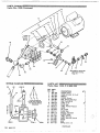
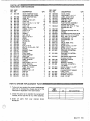
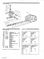
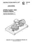
1
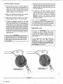
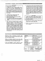
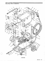
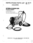
This manual contains IPAPQRTANT
WARNINGS and 1NSTRUCTIONS
READ AND RETAIN FOR REFERENCE
P I N 800-233SERIES "A"
er
1200 psi (82 bar) OPERATING PRESSURE
..
.
GWACQ BNC. P.O. BOX 1441 MWINNEAPOILUS, W
W
M 554404
OCOPYRIGHT 1987 GRACO INC.
Gesaeual S a f e t y
This pressure washer generates very high fluid
pressure. Spray from the gun. leaks or ruptured
components can inject fluid throughyour skin and
into your body and cause extremely serious bodily
injury, including the need for amputation.
Also, fluid
injected or splashed into theeyes or on the skincan
cause serious damage. In addition, some cleaning
solutions may be toxic and can
cause chemical burns,
skin irritations, and allergic reactions
if inhaled or if
they come in contact with the
body or eyes. Always
follow these precautions when operating your
pressure washing system to reduce the risk of
serious bodily injury.
NEVERpointthespraygunatanyoneoratanypartof
the body. NEVER use the spray gun without the
wand. NEVER put hand or fingers
over the spray tip.
NEVER try to stop or deflect leakswith your hand or
body.
ALWAYS be sure equipment safety devices are
operating properly before each
use.
Use this pump only for pumping water
and waterdiluted cleaning solutions.NEVER use the pump for
paint or any other coatings.
ALWAYS wear protective eyewear and appropriate
clothing to protect yourself from the
overspray and
the debris that isremoved as you clean.
Read and follow the cleaning chemical
manufacturer's recommendations on preparation
and use of the cleaning solution, and the use of
breathing apparatus and proper ventilation.
Pressure Relief Procedure
To reduce the riskof serious bodily injury, including
fluid injection and splashing in theeyes, or on the
skin, always follow this procedure whenever you
shut off the pump, when checking or servicing any
part of the system,when installing or changing
spray
tips, and wheneveryou stop sprayingfor more than
IO minutes.
1. Engage the gun triggersafety latch.
2. Turn pressurewasher OFF.
3. Remove the power cord from outlet.
4. Shut off the water supply.
5. Disengage the trigger safety latch and trigger the
gun to relieve pressure, and engage the latch
again.
Spray Gun Safety
Do not remove or modify any partof the gun; this can
cause a malfunction and result in serious bodily
injury.
Safety Latch
ALWAYS engage the gun safety latch whenever you
stopcleaning,evenforamoment.ThelatchMUSTBE
pushed fully down to make the gun inoperative.
in
Failure to properlyset the safety latch can result
accidental triggeringof the gun.See Figure 2, page 6.
Spray Tip Safety
Use extreme caution when cleaning or changing
spray tips. If the spray tip clogs while spraying,
engage the gun safety latch immediately.
ALWAYS
follow the Pressure Relief Procedure and then
remove thespray tip toclean it.
MEDICAL TREATMENT
If any fluid appears to penetrate your skin, get
EMERGENCY MEDICAL CARE AT ONCE. DO
MOT TREAT AS A .§IMFW CUT. Tell the doctor
exactly what fluid was injected.
~
~
~
~~
~~
"
Note To Physician: Injection in the skin is a
traumatic injury. It is important to treat the
injury surgically as soon as possible. Do not
delay treatment to research toxicity.
Toxicity is a
concern with some exotic coatings injected
directly into the bloodstream. Consultation with
a plastic surgeon or reconstructive hand
surgeon may~beadvisable.
2
..
.
.
.
..:.. .':.~,
, ,.
..
.
.
.
. . ...
...
802-777
. .
.
.,
~
.
~
HAZARD
,
.
~
~
~
~
NEVER use a damaged hose. Before each use, check
entire hose for cuts,leaks, abrasion, bulging cover, or
eapleoai Safeuy
If any of
damage or movement of the hose couplings.
these conditions exist, replace the
hose immediately.
Any misuse of the pressure washer oraccessories,
DO NOT try to recouple high pressure
hose or mend it
such as overpressurizing, modifying parts, using
with tape or any other device. A repaired hosecannot
incompatible chemicals and fluids, or using worn
or
damaged parts, can cause them to rupture and result contain the high pressure fluid.
in fluid injection, splashing
in the eyesor ontheskin,
HANDLE AND ROUTE HOSES CAREFULLY. Do not
or other serious bodily injuryor property damage.
Do not
pull on hoses to move the pressure washer.
use chemicals which are not com.patible with the
NEVER alter or modify any part of this equipment,
inner tube andcover of the hose. DO NOT expose
doing so could cause it to malfunction.
Graco hose to temperatures above 200OF (94OC) or
CHECK all cleaning equipment regularlyand repairor below -4OOF (-4OoCJ.
replace worn or damaged parts immediately.
If using a chemical injector, read and follow the
chemical manufacturer's literatureregarding the
use
of protective eyewear, clothing and equipment.
$yStWDl
Pl'eSSM6e
This sprayer can develop 1800 psi (123 bar)
MAXIMUM WORKING PRESSURE. Be sure that all
spray equipment and accessories are rated to
withstand the maximum working pressureof this
sprayer. DO NOT exceed the maximum working
pressure of any component or accessory used in the
system.
Chemical Compatibility
BE SURE that all chemicals used in the chemical
injector are compatible with thewetted parts of the
hose, gun, wand and tip, as given in the Technical
Data on the back cover. Always read the chemical
manufacturer's literature before using
any chemical
in this pressure washer.
~~~~~~~~A~ ~
~
~
A
NEVER operate the pressure washerwithouttheunit
being properly grounded. This includes internal
must be intact),and
wiring on unit, plug (ground plug
building wiring.
Because water is a natural
conductor, it is very important to provide a good
ground circuit to avoid serious bodily injury if
equipment should fail.
Moving partscan pinch or amputate your fingers or
other body parts.
KEEP CLEAR of moving partswhen
starting or operating the pressure washer. Followthe
Pressure Relief Procedure,page 2,before checking
or servicing the pressure washer
to prevent
discharging high pressure fluid from
the gun.
IMPORPAMB
High pressure fluid in the hoses can be very
dangerous. If the hose develops a leak,.split or
rupture due to anykind of wear, damage or misuse,
the high pressure spray emitted from
it cancause a
fluid injection injury or other serious bodily or
injury
property damage.
each
TIGHTEN all fluid connections securely before
use.Highpressurefluidcandislodgealoosecoupling
or allow high pressurespray to be emitted from the
coupling.
United States Government safety standards have
been adopted under the, Occupational Safety and
Health Act. These standards-particularly the
General Standards, Part 1910, and the Construction
Standards, Part 1926-should be consulted.
TERMS
WVAi~bJukG:
Alerts user to avoid or correct
conditions that could cause bodily injury.
CAUTION: Alerts user to avoid or correct
conditions that couldcause damage toor destruction
of equipment.
NOTE: I d e n t i f i e s h e l p f u l p r o c e d u r e s a n d
information.
802-777
3
>..
s.
..
1. Remove the twohood bolts, flatsand locks, from
the center bottom of each side of the hood. Pivot
the hood open.
2. Position the handle into the end
of the chassis
closest to the wheels. Line
up the four mounting
holes. Install the four
318 x 1 inch bolts from the
outside of the chassis. Use flat washers onlyon
head of bolt. Use a flat washer,lock washer,and
nut on each bolt on the inside of the chassis.
3.Connect one end of the 30 foot high pressure
hose to the pump outlet.
This connection is
made
with a threaded swivel fitting.Connect the other
end tothe gun using the quickcouplers provided,
4
,.. .
.. ..
002-777
.
.. . ,
..
performance, and chemical injector
performance.
.. .
4. Hood may now be closed and secured with hood
bolts, flat washers, and lock washers removed in
Steu 1 .
5. Remove the plastic plug from the inlet hose.
Check the water supply flow rate (see
page 5).
Connect inlet hose to water supply.A standard
3/4" garden hose may be-used to connect inlet
hose to the water supply.
i..
..
~.
, .
.
.... ..'....
.. ,.:
.
.>
.
,
:
Water Supply
CAUTION
Before connecting the water supply to the
pump, check your local plumbing
code
regarding cross-connectionto thewatersupply.
A backflow preventor. Part No. 801-133, is
available to prevent the back flow of
contaminated water intothefreshwatersupply.
Install upstream from the
pump.
DO NOT exceed 160°F (7OOC) inlet water
temperature.
Higher’ temperatures will damage the pump
packings.
A. Check flow rateof the watersupply. It must
be a t least 4 gpm or the pressurewasher will
not develop full pressure.
6. To check flow rate, time how long
it takes to
fill a standard five gallonpail; it should take
no longer than 1 minute and15 seconds.
Electrical Supply
7. Connect electrical cord to the proper power
supply. The electrical service required is single
phase, 230V. 60 Hz AC, 20 Amp. Electrical
service must include a ground wire. If an
extension cord isused, it must have a ground
wire and be atleast No. 12 gage wire. Extension
cord must notbe over 100 feet long.
START-UP
Use this procedureeach time you start thepressure
washer to help ensure the pressure washer
is ready
to operate and thatyou start it safely.
1. Check pump oil level. Look at oil levelindicator
window through inspectionhole in side of the
hood.’ Pump also has a dipstick located under
hood on topof pump. Oil level should up
beto dot
on oil level indicator window and within the
notch on dipstick. Add
SAE 20 or 30-weight nondetergent oil as necessary. (SAE 30-weight nondetergent oil ispreferred.)
2.Connect pressure washer to water
supply and to
proper electrical service as described in set-up.
3. Turn water supply on and trigger the gun
until
water sprays from the tip and all airpurged
is
from thesystem.
4. Turn switch on control panel
to “ON”
5. Always engage the gun’s triggersafety latch
whenever you stopspraying. even for a moment,
to reduce the risk of fluid injection or
splashing in
the eyes or on theskin if thegun is bumped or
triggered accidentally.
6. Most pressure washerspraying is done at full
pressure. If a reduced pressureis desired for a
special application, there are two methods to
reduce the maximum output from the
pressure
washer.
a.
Turn the pressure control knob on the
unloader counterclockwise, as needed. This
method is best if
you are operating
consistently ata reduced pressure.
b. Turn chemical selector valve to the “OFF”
position, then open the adjustable nozzle on
the endof the spray wand, as needed. This
method is best to quickly
reduce pressurefor
a special application.
DO NOT attempt toadjust the adjustable nozzle
when the ,spray gun isin use. Be sure that the
safety latch on the gun is in “ON”
the position
before adjusting toavoid seriousbodilyinjuryor
7. Always observe the following cautions to help
avoid costly damage to
your pressure washer.
CAUTION
DO NOT allow thepressure washer to idle for
more than 10 minutes. The unit is equipped
with a thermal relief valve to help avoid the
recirculating water from becoming too hot and
seriously damaging the pump, but it is a good
idea to turn thepressure washer off if you are
not spraying or cleaning at least every 10
minutes.
DO NOT run the pumpdry, which will quickly
damage the pump.Be sure the watersupply is
fully turned on before starting pump.
the
DO NOT operate the pressure washer with the
inlet screen removed. This screen helps keep
abrasive sediment outof the pump, which could
clog or scratch the pump.
DO NOTpumpcaustic materials; such materials
may corrode and damage the pumpcomponents.
C h e m i c a l Injector Operation
12. Adjust the chemical mixture(s)
with the chemical
metering valve(s) on the control panel.
Once the
chemical metering valve(s) are adjusted to the
desired setting, they may be left there for future
chemical applications.
8. Be sure that the control ringon the injector is
open t w o full turns from the
closed position. To
check this, the hood must be opened. Once the
control ring is open, it may be left alone. The
chemical mixture is controlled by the chemical
metering valves on the controlpanel.
13. To change to the other chemical, turn the
chemical selector valve to the other
chemical. To
shut off chemical, turn the chemical selector
valve to the "OFF" position, or close the
adjustable nozzle. The chemical metering
valve(s) do not have to beclosed to change or shut
off chemical supply.
9. Place the chemical strainer@) and chemical
line(s) intoyour chemical container(s).
10. Select which chemical you want use
to with the
chemical selector valve on the control panel.
1 1 . To apply the cleaning chemical to the work
of the
surface, the adjustable nozzle on the end
spray wand must beopen. The chemical(s) can
only be drawn into the water
stream, and applied
to the work
surface in a l o w pressure situation.
By openingthe adjustablenozzle you create low
pressure. Closing it produces high pressure for
rinsing and pre-chemical flushingor nochemical
cleaning. Onechemical maybe turned off and on
at the gun by using the adjustable nozzle as
described above.
CAUTION
the wetted parts shown
in the technicaldata at
the end of this manualto avoid serious damage
Trigger Safety Latch
-
WARNING
when thespray gun isin use. Be sure that the
safety latch on the gun in
is the "ON" position
before adjusting to avoid serious bodily injuryor
WARNING
To reduce the risk of serious bodily injury,
including fluid injection,splashing in the eyes
or on the skin, ALWAYS engage the trigger
safety latch whenever you stop spraying, even
for a moment.
In the engage position, the trigger safety latch
prevents the gun from
being triggered
accidentally by hand or if it is dropped or
bumped. Be sure the latch isfullyseated inslot
in handle or it cannot prevent thegun from
being triggered. See Figure 2.
FIGURE 2
...
6 802-777
..,~.
-. ,.. .~. . . .
,. . . .
.. -. .
.~
. . ... .
~
,,
. .. ..~,
.
. .
... .
.. .. ...
,
~~~~U~~
Pwssure Relief Procedure
To reduce the risk of serious bodily injury,
including fluid injection and splashing in the
eyes, or on the skin, ALWAYS follow this
procedure whenever you shut off the pump,
when checking or servicing any part of the
system, when installingor changing spray tips,
and wheneveryou stop spraying for more
than
10 minutes.
1. Engage the gumtrigger safety latch.
2.
If the pressure washerwill beexposedtofreezing
temperatures, drain all water out of the pump. If
you must store the pressure washer in freezing
temperatures, flush it with a 50% antifreeze
solution. This canbe done by placing theend of
the inlet hose into a bucket of 50% antifreeze
solution. Start the pressure
washer. Trigger the
gun for 10 seconds, release the trigger for 10
seconds. Trigger and release about 10 times or
untilthe5046antifreezesolutioncomesoutofthe
spray tip.
2. Turn the pressurewasher off.
3. Remove the power cord from the outlet,
4. Shut off water supply.
5. Disengage the triggersafety latch and trigger
the gun to relieve
pressure, and engage latch
again.
1. After using the chemical injector system, it
should be flushed out with water or a 50%
antifreeze solution if unit will be exposed to
freezing temperatures. This is best done by
replacing the chemical container@)
with a bucket
of water or a 50% antifreeze solution. Operate
pressure washer as described in start-up. Draw
water or antifreeze solution into both chemical
lines until it passes through the injector. By
flushing the chemical injectorsystem, you will
help avoid unnecessary wear
and prolong the life
of components.
CAUTION
thaw it ina warm room before trying to start
it.
Do not pour hot water
on the pump; it may crack
3. After each use, wipe all surfaces
of the pressure
washer with aclean, damp cloth.
4. Perform the appropriate maintenance.See the
chart ompage 7.
MAINTENANCE
Observing regular maintenance intervals helps
ensure that you get maximum performance
and life
from your pressure washer.
There is a break-in period for the pump. After
changing the oil after the
pump's break-in period, the
interval between requiredchanges is longer,
If you are operating in dusty conditions, these
maintenance checks should be made more often.
WHAT TO DO
INTERVAL
Daily
Clean water inlet screen.
Check pump oil level.
Fill as necessary.
After first
50 hours of
operation.
Change pump break-in oil.
Use SAE 20W or 30W
non-detergent oil*.
Each 500 hours
of operation or
3 months.
Change pump oil.
Use SAE 20W or 3 0 W
non-detergent oil*.
OIL CAPACITY
Pump
15.2 Oz.
1.45 liters)
TYPE
SAE 20W or 30W
Non-Detergent*
*SAE 30-weightnon-detergent oil ispreferred.
..
..
802-777
7
TROUBLESHOOTING CHART.
~A~~~~~
To reduce the risk of serious bodily injury, including fluid injection,
splashing in theeyes or on the
skin, or
injury from moving
parts, always follow the
Pressure Relief Procedure Warning page
on 7 before proceeding.
PROBLEM
CAUSE
SOLUTION
Low Pressure
Worn noale.
Coupling slippage.
Air leak in inlet plumbing.
Replace with noaleof propersize.
Tighten orreplace.
Disassemble, reseal, replace bad parts,
and reassemble.
Clean. Use adequate size. Checkmore
frequently.
Install proper filter.Check flow available to
pump. Replace packings.
Inlet filter clogged.
Worn packing. Abrasivesin
pumped fluid or severe cavitation. Inadequate water supply.
Fouled ordirty inlet or discharge valves.
Worn inlet or discharge valves.
Leaky discharge hose.
Pressure adjustment set down.
Pump runs exiremely
rough, pressure low.
Replace worn valves, valve seats and/or
discharge hose.
Turn adjustment knobin to increase
pressure.
Proper size inlet plumbing; check for air
tight seal.
Clean out foreign material, replaceworn
valves.
Restricted inlet or air
entering the inlet plumbing.
Inlet restrictions and/orair
eaks. Stuck inlet or discharge
ilalve.
Leaking high pressure seals.
nadeouate water'suoolv.
aorn packings.
Water leakage from under
the manifold.
Water in pump crankcase.
Replace seals.
Check flow available to oumo.
Replace packings
Norn packings.
3il seal leaking.
May be caused byhumid air
:ondensing into water inside
he crankcase.
scored, damaged, orworn
hngers.
Urasive material in the water
)eing pumped.
nlet water temperature too
ligh.
Iver pressurizing pump.
Frequent or premature
failure of the packing.
Replace packings.
Replace oil seals.
Change oil at 3 month or 500 hour intervals.
Xeplace plungers.
nstall proper inletfilter.
:heck inlet water temperature; be
iure not to exceed 1 6OoF.
Jo not modify any factory-set
tdjustments.
:lean or replace tip.
ixcessive pressure dueto
lartially pluggedor damaged tip
'ump running too long
vithout spraying or cleaning.
iunning pump dry.
breign particles in the inlet or
,ischarge valve, orworn inlet
nd/or discharge valves.
hit not plugged in.
'lectric motor overheated
Strong surging atthe inlet
and low pressure on the
discharge side.
Unit will not start.
Uever run pump morethan 10
ninutes without spraying or cleaning.
10 not run pump without water.
leplace or cleanvalves.
:heck power cord.
.et motor cool andpush reset bunon
In motor.
:heck fuse/circuit breaker panel.
)isassemble chemical valveand clean.
:heck and clean chemical hose and
filter.
'urn control ring on noale clockwise
1 cause drop in pressure:
:heck level of chemical.
lectric service off.
:hemica1 injector clogged.
Chemical injection system
doesn't work.
8
Clean inlet and discharge valve assemblies.
>djustablenoale completely
Iosed.
3w chemical level.
802-777
~~
....
~
,.
~
..,....
,,
.,,
.,
... -.
.
.
.. . .
~~~
..
..
.
PUMP SERVICE
~
A
~
~
O
~
~
To reduce the riskof serious bodily injury, including fluid injection, splashing
in the eyes oron the skin,or
injury from moving parts, always follow the Pressure Relief Procedure Warning on page 7 before
proceeding.
NOTE: The following metric wrenches are
needed: M 6 Allen wrench, M10, and M30.
A pump repair tool
kit, P/N 800-271, is available. It includes packing, extraction
and insertion tools
Repair kits are available.Refer to the individual repairsections,and the parts pageformore details. For
the best results, use all the parts in the kit.
Valves
NOTE: To replace valves, order kit partno. 801 472.
1. Remove the hex plug (205) from the manifold
(206) using anM30 wrench..
2. Examine the O-ring (204) under the plug and
replace it if it is cutor distorted.
3. Remove the valve assembly(203)from thecavity;
the assembly maycome apart.
4. Install a new valve (203). Install the O-ring (204)
and plug (205) and torque'to
75 ft-lb (10.3Nm).
NOTE: Retorque the plug after 5 hours of
operation.
. .
1. Remove the eight Allen head cap screws (201)
and lockwasher (202) fromthe manifold (206)
using a M 6 Allen wrench.
2. Carefully separate the manifold
from the
crankcase. It may be necessry totapthe manifold
lightly with a rubber mallet.
CAUTION
-
3. Carefully examine each plunger (221) and
replace it if there is any
scoring.
Servicing The V-Packings
NOTE: To replace just the v-packings, use kit
will service the
part no. 801 -662 which
entire pump.
. ... .:, ..,
:
,_ ..
3. Remove the v-packing(212)and head ring (211).
Pull out the intermediate retainer ring (213).
Remove the v-packing(212) and head ring (211).
4. Inspect all parts and replace as necessary.
5.Thoroughly clean the packing cavities
examine.
and
6. Lightly grease. the packing cavities and then
replace the packings
in the following
order: head
ring (211). v-packing (212). intermediate ring
(213),headring(211),packing(212),andpacking
order and facing the correct direction. See
will cause a
Figure 4. Improperly installed parts
malfunction.
7. Reassemble the manifoldas instructed inSteps 7
and 8 of Servicing The Plungers.
Servicing The Plungers
To avoid damaging the plungers or seals, keep
,
manifold. Examine the
O-ring (215) and replace it
if it is cut or damaged.
retainer(214). with the
O-ring (215) installed into
the retainer groove.
Pumping Section
the manifold properly aligned
with theceramic
plungers when removingit.
2. Carefullypull the packing retainer(214)from
the
-To replace the v-packings, rings and
retainers, orderthree ofkit part
no. 801 664 toservice the entirepump.
;
:
1. If the manifold is notalready removed, follow
Steps 1 and 2of pumping section.
NOTE: Plunger repair kit, part no. 801-474, is
available to service allthe plungers.
1. Loosen the plungerretaining screws (21
7). 5 to 6
turns, using an M10 wrench.Push the plunger
(221) toward the crankcase to separate the
plunger and retaining screw.
2. Remove the screw (217) fromthe plunger and
examine theO-ring (219).backup ring (220) and
copper bearing/gasket washer (218). Replace
these parts, if necessary, using kit partno. 801474.
3. Remove the plunger (221) and flinger (222)from
the plunger shaft. Clean, examine and replace
parts as necessary.
802-777
9
4. Inspect the plunger shaft for leakage
oil
from the
crankcase. If leaking is obvious, replace the oil
.seals (216).Otherwise, DO NOT remove these
seals as they cannot be reused.
8. Install theeight Allen head capscrews(20l)and
washers (202)finger tight.Torque the screws to
15.9 ft-lb (2.2 Nm) following the tightening
pattern in Figure 3.Uneven tightening maycause
the manifold to bind
or jam.
NOTE: Oil Seal .Kit, part no. 801-658, is
available to replace all threeseals.
5. Lightly grease the oilseal (ifit is beingreplaced)
and the flinger, and
replace them on the plunger
shaft. Then install the plunger.
6. Lightly grease the retaining screw (217)
and the
outer end of the plunger.Place the washer(218).
O-ring (214) andbackup ring (220) around the
screw and install the screw through the plunger.
Torque to 14.4 ft-lb(2 Nrn).
NOTE: If you plan toreplace the packings, go to
Servicing the V-Packings.
7. Lubricate the outside of each plunger. Slide the
manifold onto the crankcase, being careful notto
damage the seals.
FIGURE 3
.
.
”.
.
FIGURE 4
.
10’ 802-777
,.....
_i
.
,
..
~. .~
....
.. .~
. .... . .
- . . . . . . .
~
. .
~
.
..
. . . ..
~.
.....
~
.,
PARTS DRAWING
Hydra-Clean 1235, P/M 800-233
(Continued)
.... . ..
.. . .
802-777 11
PARTS DRAWING
Hydra-Clean 12 35
WIRING DIAGRAM
PARTS LIST
Hydra-Clean 1235, P / N 8 0 0 - 2 3 3
REF. PART
NO. NO.
1 802-760
2 801-892
4 801-223
5 801-894
6 802-980
7 801-931
8 802-153
9 802-685
10 801-417
11 802-664
12 801 -883
13 802-751
14 800-1 18
15 801-957
16 801-129
17 801-386
18 601-935
19 802-699
20 801-103
ON.
DESCRIPTION
COVER, Switch
CORD W/PLUG, 12/3 x 8'
SWITCH
SCREW, Ground
BOX. Switch (with plug)
GRIP., Cord lPB1D
,. - .-,
CORD (12/3)
PLATE. Ins.
LABEL, Relieve Pressure
1
1
'
1
1
1
-
'
2
~~~~
36"
1
1
1
1
HOOD
TIP (15065)
PANEL. End
NOZZG, Adjustable
SLEEVE. Safetv
LABEL Warniig
LABEL, Warning, Ground
1
GUN
NIPPLE, 3/8 x 1/4
1
1
1
1
1
WAND
. .. ...-
1
1
(Continued)
. ~ .. .
~~
..
. .
..
. . . .
~.,
..
,
-
.. . .
.
... .
.. .....
. ...
.
... . .
. ..
.
... .
..
.
.,.
.
.~
.,
':
REF. PART
NO. NO.
21 801-009
22 801-090
23 801-967
24 801-605
25 801-875
27 801-546
28 801-015
29 801-363
30 801:214
31 801-813
33 801-025
34 801-023
35 802-729
36 801-878
37 801-818
38 801.879
39 801-235
40 801-880
41 801-857
42 802-648
43 801-024
44 801-940
45 802-703
46 800-247
47 802-730
48 801:910
49 801-112
50 802-735
51 801-683
52 801-501
53 800-246
54 802-669
55 802-683
56 801-937
57 802-636
58 802-843
59 802-733
60. 802-731
61 802-732
62 801-547
63 802.292
DESCRIPTION
QUICK COUPLER. Female
(Includes 801-202 0-Ring)
QUICK COUPLER, Male
HOSE, 30
SCREW, 10-24 x 3/4
LOCK, #lo
BOLT, 3/8-16 x 1-1/4, "G5'
FLAT, 5/16
LOCK, 3/8
BOLT, 3/8-16 x 1-3/4
TUBING, 1/4 I.D.
LOCK, 5/16
FLAT, 1/4
HANDLE
NUT, 3 0 - 16
BOLT. 3/8-18 x 1
WHEEL
FLAT, 518
COTTER PIN
AXLE
PIVOT
NUT, 5/16-18
BOLT, 5/16-18 x 3/4, "G5"
CASTER
BRACKET. Caster
BUMPER
PLUG, Plastic
FILTEWWASHER
HOSE, Inlet
STRAINER, Chemical
LABEL Serial No.
CHASSIS
HOSE BARB, 1/8 x 1/4
VALVE, Metering
LOCKNUT, 1/2 Electrical
PANEL, End, Control
LABEL Knob
SCREW, 6-32 x 1/2
LOCK. #6
FLAT, #6
FLAT, 3/4
FLAT, #10
QN.
1
1
1
10
10
2
16
14
2
16'
4
4
1
4
10
2
4
2
1
2
4
4
1
1
1
1
1
1
2
1
1
4
2
1
1
2
4
4
4
1
A
REF. PART
NO. No.
64 802-684
65 801-733
66 802-686
67 801-221
68 801-305
69 802-052
70 800.248
71
802-625
72
73
74
75
76
77
78
79
80
81
82
83
84
85
86
802-783
802-698
801-887
802-633
802-785
802-786
802-784
801-139
802-629
800-115
801-622
801.178
801-523
802-086
801-891
87
801-890
88
802-842
89 800-138
90 801-900
91 802-752
92 801-881
93 801-620
94 801-866
95 801-524
96 801-905
97 801-907
98 801-709
DESCRIPTION
QN.
VALVE, 3-Way
1
3
HOSE BARB, 1/4 x 114
1
LABEL Control Panel
CONNECTOR, Crimp
3
WIRE NUT. Yellow
4
WIRE NUT; Red
1
PUMP/MOTOR ASSEMBLY
1
(Includes items71-80)
MOTOR. 3HP. TEFC. " C Face
1
(Includes item 72)
1
KEY
1
COUPLING (Includes item74)
1
SWDER
1
HOUSING (Includes items76-79)
BOLT, 1/2-13 x 1-1/4" SHCS
4
BOLT, M6 x 16 mm SHCS
4
LOCKWASHER. 1/2
4
LOCKWASHER. 1/4
1
PUMP
1
VALVE. Relief.Temo.
1
CROSS, 1/2 "
'
1
ELBOW, Street, 1/2 x 90°
1
NIPPLE, 1/2 x 2"
2
ELBOW. Street. 3/8 x 45'
COUPLING, 318 NPT(M) x
1
3/8 NPSIM)
COUPLING, 3/8 NPT(M)x
'1
3/8 NPSIFI
UNLOADER, Replacement
1
(Includes item98)
1
INJECTOR, Chemical
1
GROMMET
.
1
SUPPORT, Unloader
COUPLING. 3/8 NPTlFI
. .x
1
1 /4 NPSIF)
1
ELBOW, Street, 1/4 x 90"
HOSE, By-Pass
1
(Includes 802-627 Adapter)
1
LABEL Pump
1
ADAPTOR. 3/8 NPT
1
WASHER, Aluminum
1
PLUG, 1/4 NPT
~
~~~~
HOW TO ORDER REPLACEMENT'PARTS
1. To be sure you receivethe correct replacement
parts, kit or accessories, always give allof the
information requestedin the chart below.
2. Check the parts list to identify the correct part
number; do not use theref no. when ordering.
6 digit
PART
NUMBER
OTY
PART DESCRIPTION
-
3. Order all parts from your nearest Graco
distributor.
802-777 13
PARTS DRAWING
Pump, 802-629
205
2
0
I
4
4
203
20;
PARTS LIST
Pump, 802-629
REF.
NO.
201
t
REPAIR KITS
PART
801-651
801-652
OIL SEAL KIT
801-658
$204
801 -470
REF.
,206
207
802-319
801-485
8014 8 4
801 -482
801 -483
216
202
t 203
$205
208
209
210
*211
t*212
*213
*214
*215
+**21 6
**217
-218
219
** 220
221
222
223
Includes:
NO.
WASHER
CAP, 318 NPT
CAP, 1/2 NPT
WASHER
".
HEAD RING
PACKING
INTERMEDIATE RING
PACKING RETAINER
O-RING
OIL SEAL
PLUNGER RETAINING SCREW
WASHER
-
801-661
801-660
801-659
QTY.
6
3
-
7
BACK-UP RING
PLUNGER
FLINGER
OIL DIPSTICK
3
3
3
1
. .. .. , . . .. .~
. ..
.
. ..
.
.
.
802-306
Includes:
NO.
204
205
I
*
PACKING & RETAIN.
ER KIT 8 0 1 -664
(Three kits needed for
entire pump)
Includes:
REF.
NO.
QTY.
21 1
14 802-777
$
REF.
3
3
. . ~. . . . . .
2
.
.
.
6
VALVE CAP KIT
Includes:
3
3
3
an.
NO.
21 2
3
VALVE KIT
801-472
6
See page 13 for "How To Order Replacement Parts"
. . ~~.~
~ ~ ,. .
. ,.
Includes:
REF.
tt
O-RING
.....
*f
+
.*x
NO.
. .
6
6
*I
PLUNGER REPAIR
KIT 8 0 1 -474
Includes:
REF.
NO.
21 7
218
219
220
~,
QTY
. .
..
QTY.
3
3
3
3
, ,
.. .;..
, . .,
..
.
...
, :
.
PARTS DRAWING
Chemical Injector, 800-138
PARTS LIST
Chemical Injector, 800-138
REF. PART
NO. NO.
DESCRIPTION
1 801-684
NIPPLE, Hex, brass, 3/8 NPT
2 801-685
O-RING
3 801-687
NOZZLE NO. 2. (16-21 I/min)
4 801-688 O-RING
5 801-689
CHEMJET BODY
6 801-690
SPRING, cone
7 801-784 BALL
8 801-692
O-iNG
9 801-693
O-RING
10 801-694 VALVESEAT
11 801-695
SPRING
12 801-696 O-RING
MRB
'13
801-697
NEEDLE/HOSE
.~~
~.
14 801-698
ADJUSTMENT KNOB
15 '801-682
SPRING, retaining
1
I
I
1
QTY.
1
1
1
1
1
1
1
k12
I
I
11
*If an extremely harsh chemicalis to beinjected,orif
corrosion problems exist,
the standard brass
needle/hose barb (ref. no. 13) may be replacedwith
a stainless steel needle/hose barb, pan no. 801 -
I
I
969.
See page 13 far "Haw Ta Order Replacement Parts"
i
I
TECHNICAL DATA
MOTOR 3 hp. single phase 230 V. 60 Hz, 2 0 Amp, TEFC
WATER PUMP:
1200 psi(83 bar) measuredat pump
3.5'GPM 113.3 liter/min)
W m E D PARTS: High Pressure Hose: Acrylonitrilie and Buna-Ncover and tube
Bypass Hose: Synthetic yarn, EPDM
Pressure Washer (including fitting): Anodized
Aluminum, Aluminum or Bronze alloys. Brass, Copper,
Nylon-PTFE
composite. Ceramic. Buna-N.
Cotton Phenolic. 316, 303, & 304 Stainless
Steel, Polymide-12 Thermo-plastic.PTFE
Carbon Steel. zinc or yellow chromate plate
UNIT WEIGHT 150 Ib. 168 kg)
OVERALL DIMENSION
MAX. INLET WATER TEMPERATURE:
Length: 38 in. (965 mm)
Width: 19 in. 1482 mm)
Height: 33 in. 1838 mm)
160°F (700c)
INLET HOSE CONNECTION 3/4" garden hose (f)
PUMP OIL CAPACITY
15.2
02.
(.45 liters)
'PTFE is a registered trademark of the DuPont
Company
802-777 15
THE GRACO WARRANTY
WARRANTY
Gram warrants all equipment manufactured by it and bearing is name tobe free from defects in
material and workmanship on the date of sale by an authorized Graco distributor to the original
purchaser for use. As purchaser's sole remedy for breach of this warranty, Graco will, for a period of
twelve months from the date of sale. repair or replace any pan of the equipment proven defective. This
warranty applies only when the equipment is installed. operated and maintained in accordance with
Graco's written recommendations.
This~rrantydoesnOtcover,andGracoshalln~tbeliablefo~,a~~malf~nction,damagearwearcau~~
by faulty installation. misapplication. abrasion, corrosion. inadequate or improper maintenance,
negligence. accident. tampering. or Substitution of non-Graco component pans..Nor shall G~~~~ be
liable for malfunction. damage or wear caused by the incompatibilify with Graco equipment of
structures. aCCeSSOri85. equipment or materials not supplied by Graco. or -the improper design.
manufacture. installation. operation or maintenance of structures, accessories. equipment or materials
not supplied by Graco.
This Warranty is conditioned upon the prepaid return of the equipment claimed to be defenive for
examination by Graco to verify the claimed defect If the claimed defect is verified, Graco will repair or
replace free of c h a w any defective pans. The equipment will be returned tothe original purchaser
transportation prepaid. If inspaction of the equipment does not disclose any defect in material or
workmanship. repairs Wil be made at a reasonable charge,which charges may include the costs of
pans. labor and transportation.
DlSCLPIlMERS AND LIMITATIONS
THE TERMS~OFTHlSW~RRANfiCOkTITUTE
PURCHASER'S SOLEAND EXCLUSIVE REMEDYAND
ARE IN LIEU OF ANY OTHER W A R R M I E S (EXPRESS OR IMPLIED). INCLUDING WARRANTY'OF
MERCHANTABILITY OR WARRANTY OF FiTNESS FOR A PARTICULAR PURPDSE.AND OF ANY NONCONTRACTUALUABILITIES, INCLUDING PRODUCTLIABILITIES.
BASEDON NEGUGENCEORSTRICT
LIABILITY. EVERY FORM OF LIABILITY FOR DIRECT, SPECIAL
OR CONSEOUENllAL DAMAGES OR
LOSS IS EXPRESSLY EXCLUDEDAND DENIED. IN NO CASE SHALL GRACO'S
UABlLllY EXCEED THE
AMOUNT OFTHE PURCHASE PRICE. ANY ACTION FOR BREACH
OFWARRANTYMUSTBE BROUGHT
WITHIN TWO (2) YEARS OF THE DATE OF SALE.
EQUIPMENT NOT COVERED BY GRACO WARRANTY
GFIACO MAKES NO W A R R A N ~ . A N ~ D ~ ~ ~ ~ ~ M S WARRAMIES
A ~ ~ ~ M ~ OF
L I MERCHANTABILE D
ITY AND FITNESS FOR A PARTICULAR PURPOSE,WiTH RESPECTTO ACCESSORIES, EOUIPMENT.
MATERIALS. OR COMPONENTS SOLD BUT NOT MANUFACTURED BY GRACO. These
items sold, but
not manufactured bv Gram (such as electric motor. switches. hose,etc.1. are subject to thewarranty, if
any. of their manufacturer. Graco will provide purchaser with reasonable assistance in making any
claim for breach of these warranties.
Factory Branches: Atlanta. Dallas. Detroit. 10s Angeles. West CaldwellIN.J.1
Subsidiary and Affiliate Companies: Canada: England: Switzerland: Francs: Germany: Hong K O ~ J~~~~
~ :
GRACO INC.
P.Q. BOX 1441 MINNEAPOLIS, MN 55440-1444
PRINTED IN U.S.A. 802-776 10/87