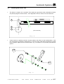
1
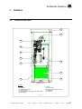
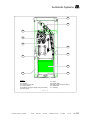
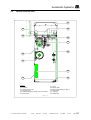
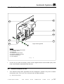
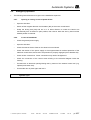
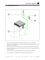
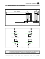
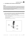
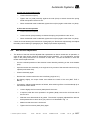
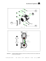
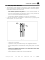
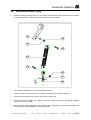
Automatic Systems -- Open and close the barrier electrically: check if the arm stops in the vertical position, with motor stopped, and if the three points (x), (y) and (z) of the crankshaft-rod device are perfectly aligned in the closed position, also with motor stopped. If not, refer to paragraph [4.4. Limit switch adjustment]. -- Check if you did not forget any tool inside the barrier. -- Remove any foreign body from the inside of the barrier (scraps, etc.) and clean. -- Replace and lock the hood. -- Replace and lock the side door. -The barrier is now operational. Although all adjustments have been carried out in factory, a final regulation may be required after the transport or mounting procedure. In this case, see chapter [4. Adjustments and technical interventions]. 3.9. • Temporary dismantling If the equipment has to be temporarily dismantled, e.g. if you need to change its place, proceed in the following order. 3.9.1. Disconnecting the equipment -- Unlock and remove the side door. -- Make sure the power supply cables are not live. -- Switch off the circuit breaker (4:1) on the electrical control board. -- Take down the electrical control board. -- Remove the phases of the power supply from the terminals L and N (4:2). -- Disconnect the earth wire from the bolt (1:10) located at the bottom of the housing inside the unit. -- Disconnect the control wires from the general connection block (4:4). -- Disconnect any other wires (from the detection loops, etc.). -- Cut off the cable binders under the electrical control board so you can detach the cables. -- Replace the electrical control board. 3.9.2. Dismantling the barrier arm -- Grasp the driving belt (1:6) and act on it to unlock the mechanism, then raise the arm by hand up to the vertical position. -- Remove the screws (5:1) and dismount the arm. together to avoid losing any. Automatic Systems BL26-GB YD-XX MQ-1302 30/11/95 Gather all screws and flat washers Installation manual 1-1103GB Rev.: B p. 15/27