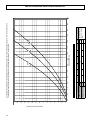
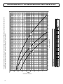
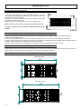
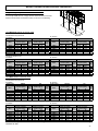
1
A
RE
F
S
E
-FRIEND
Y
R
E
IG
RA N
T
G
AIR COOLED WATER CHILLERS
AND HEAT PUMPS WITH AXIAL FANS
O
L
RHA
C
351 ÷ 625 kW in cooling mode
370 ÷ 658 kW in heating mode
INSTALLATION MANUAL
1
Dear Customer,
Thank you for having purchased a FERROLI Idustrial coolers. It is the result of many years experience, particular research and has
been made with top quality materials and higlly advanced technologies.The CE mark guaranteed thats the appliances meets European Machine Directive requirements regarding safety.
The qualitative level is kept under constant surveillance. FERROLI products therefore offer SAFETY, QUALITY and RELIABILITY.
Due to the continuous improvements in technologies and materials, the product specification as well as performances are subject to
variations without prior notice.
Thank you once again for your preference. FERROLI S.p.A
The manufacturer declines all responsibility for any inaccuracies in this manual due to printing or typing errors.
The manufacturer reserves the right to modify the products contents in this catalogue without previous notice.
2
TABLE OF CONTENTS
THIS MANUAL IS DIVIDED INTO SECTIONS. THEIR NAMES APPEAR IN THE HEADING OF EACH PAGE.
GENERAL SPECIFICATIONS . . . . . . . . . . . . . . . . . . . . . . . . . . . . . . 4
General specifications . . . . . . . . . . . . . . . . . . . . . . . . . . . . . . . . . . 4
European Directives . . . . . . . . . . . . . . . . . . . . . . . . . . . . . . . . . . . 4
Identification plate of the Unit . . . . . . . . . . . . . . . . . . . . . . . . . . . . 4
Presentation of the unit . . . . . . . . . . . . . . . . . . . . . . . . . . . . . . . . . 5
Identification code of the unit . . . . . . . . . . . . . . . . . . . . . . . . . . . . 5
Description of the components . . . . . . . . . . . . . . . . . . . . . . . . . . . 6
Version with Desuperheater VD (available for both IR units and IP units) . 8
ACCESSORIES AND OPTIONAL EQUIPMENT . . . . . . . . . . . . . . . . 9
Mechanical accessories . . . . . . . . . . . . . . . . . . . . . . . . . . . . . . . . 9
Electrical accessories . . . . . . . . . . . . . . . . . . . . . . . . . . . . . . . . . . 12
Mechanical options . . . . . . . . . . . . . . . . . . . . . . . . . . . . . . . . . . . . 12
Electrical options . . . . . . . . . . . . . . . . . . . . . . . . . . . . . . . . . . . . . . 12
GENERAL TECHNICAL specification . . . . . . . . . . . . . . . . . . . . 13
General technical specifications . . . . . . . . . . . . . . . . . . . . . . . . . . 13
nominal performances . . . . . . . . . . . . . . . . . . . . . . . . . . . . . . 14
Standard unit AB - MEDIUM TEMPERATURE PLANT Data certified by EUROVENT . . . . . . . . . . . . . . . . . . . . . . . . . . . . 14
Standard unit AB - LOW TEMPERATURE PLANT . . . . . . . . . . . . 14
Standard unit AB - MEDIUM TEMPERATURE PLANT Data declared according to UNI EN 14511 . . . . . . . . . . . . . . . . . . 15
Standard unit AB - LOW TEMPERATURE PLANT Data declared according to UNI EN 14511 . . . . . . . . . . . . . . . . . . 15
Low noise unit AS - MEDIUM TEMPERATURE PLANT Data certified by EUROVENT . . . . . . . . . . . . . . . . . . . . . . . . . . . . 16
Low noise unit AS - LOW TEMPERATURE PLANT . . . . . . . . . . . 16
Low noise unit AS - MEDIUM TEMPERATURE PLANT Data declared according to UNI EN 14511 . . . . . . . . . . . . . . . . . . 17
Low noise unit AS - LOW TEMPERATURE PLANT Data declared according to UNI EN 14511 . . . . . . . . . . . . . . . . . . 17
Extra low noise unit AX - MEDIUM TEMPERATURE PLANT Data certified by EUROVENT . . . . . . . . . . . . . . . . . . . . . . . . . . . . 18
Extra low noise unit AX - LOW TEMPERATURE PLANT . . . . . . . 18
Extra low noise unit AX - MEDIUM TEMPERATURE PLANT Data declared according to UNI EN 14511 . . . . . . . . . . . . . . . . . . 19
Extra low noise unit AX - LOW TEMPERATURE PLANT Data declared according to UNI EN 14511 . . . . . . . . . . . . . . . . . . 19
STANDARD PERFORMANCES - IR COOLING UNIT ONLY . . . . . . 20
Performances - Standard unit AB . . . . . . . . . . . . . . . . . . . . . . . . . 20
Performances - Low noise unit AS . . . . . . . . . . . . . . . . . . . . . . . . 21
Performances - Extra low noise unit AX . . . . . . . . . . . . . . . . . . . . 22
STANDARD PERFORMANCES - IP HEAT PUMP UNITS . . . . . . . . 23
Performances in cooling mode - Standard Unit AB . . . . . . . . . . . . 23
Performances in heating mode - Standard Unit AB . . . . . . . . . . . 24
Performances in cooling mode - Low noise Unit AS . . . . . . . . . . . 25
Performances in heating mode - Low noise Unit AS . . . . . . . . . . . 26
Performances in cooling mode - Extra low noise Unit AX . . . . . . . 27
Performances in heating mode - Extra low noise Unit AX . . . . . . . 28
Correction factor for the use of glycol . . . . . . . . . . . 29
Correction factor for the use of glycol IN HEATING MODE . . . . . 29
Correction factor for the use of glycol IN COOLING MODE . . . . . 29
Fouling factors . . . . . . . . . . . . . . . . . . . . . . . . . . . . . . . . . . . . . . . . 29
GENERAL SPECIFICATIONS - BRINE UNIT BR - BP . . . . . . . . . . . 30
Brine Unit (BR) . . . . . . . . . . . . . . . . . . . . . . . . . . . . . . . . . . . . . . . 30
GENERAL SPECIFICATIONS - Version with Desuperheater
(VD) IR COOLING UNIT ONLY . . . . . . . . . . . . . . . . . . . . . . . . . . . . . 31
Acoustic Version: AB (Standard Unit) . . . . . . . . . . . . . . . . . . . . . . 31
Acoustic Version: AS (Low noise Unit) . . . . . . . . . . . . . . . . . . . . . 31
Acoustic Version: AX (Extra low noise Unit) . . . . . . . . . . . . . . . . . 31
Performances Version with Desuperheater (VD) . . . . . . . . . . . . . 32
GENERAL SPECIFICATIONS - Version with Desuperheater
(VD) IP HEAT PUMP UNIT . . . . . . . . . . . . . . . . . . . . . . . . . . . . . . . . . 33
Acoustic Version: AB (Standard Unit) . . . . . . . . . . . . . . . . . . . . . . 33
Acoustic Version: AS (Low noise Unit) . . . . . . . . . . . . . . . . . . . . . 33
Acoustic Version: AX (Extra low noise Unit) . . . . . . . . . . . . . . . . . 33
Performances Version with Desuperheater (VD) . . . . . . . . . . . . . 34
GENERAL SPECIFICATIONS - full heat recovery unit (Vr)
IP HEAT PUMP UNIT . . . . . . . . . . . . . . . . . . . . . . . . . . . . . . . . . . . . . 35
Acoustic Version: AB (Basic Unit) . . . . . . . . . . . . . . . . . . . . . . . . 35
Acoustic Version: AS (Low noise Unit) . . . . . . . . . . . . . . . . . . . . . 35
Acoustic Version: AX (Extra Low noise Unit) . . . . . . . . . . . . . . . . 35
Full Heat recovery unit performances (VR) . . . . . . . . . . . . . . . . . 36
NOISE LEVELS . . . . . . . . . . . . . . . . . . . . . . . . . . . . . . . . . . . . . . . . . 37
Standard Unit AB . . . . . . . . . . . . . . . . . . . . . . . . . . . . . . . . . . . . . . 37
Low noise unit AS . . . . . . . . . . . . . . . . . . . . . . . . . . . . . . . . . . . . . 37
Extra low moise unit AX . . . . . . . . . . . . . . . . . . . . . . . . . . . . . . . . 37
OPERATING RANGE . . . . . . . . . . . . . . . . . . . . . . . . . . . . . . . . . . . . . 38
Operating range . . . . . . . . . . . . . . . . . . . . . . . . . . . . . . . . . . . . . . 38
Water pressure drop EVAPORATOR . . . . . . . . . . . . . . . . . . . 39
Operating range . . . . . . . . . . . . . . . . . . . . . . . . . . . . . . . . . . . . . . 39
Water pressure drop DESUPERHEATER . . . . . . . . . . . . . . . 40
Operating range . . . . . . . . . . . . . . . . . . . . . . . . . . . . . . . . . . . . . . 40
WORKING HEAD OF THE PUMPING MODULE MP AM STD AND MP SS STD . . 41
Operating range . . . . . . . . . . . . . . . . . . . . . . . . . . . . . . . . . . . . . . 41
HIGH WORKING HEAD OF THE PUMPING MODULE MP AM HP1
AND MP SS HP1 . . . . . . . . . . . . . . . . . . . . . . . . . . . . . . . . . . . . . . . . . 42
Operating range . . . . . . . . . . . . . . . . . . . . . . . . . . . . . . . . . . . . . . 42
RECEPTION AND POSITIONING . . . . . . . . . . . . . . . . . . . . . . . . . . . 43
Inspections on arrival . . . . . . . . . . . . . . . . . . . . . . . . . . . . . . . . . . 43
Safety prescriptions . . . . . . . . . . . . . . . . . . . . . . . . . . . . . . . . . . . . 43
Handling . . . . . . . . . . . . . . . . . . . . . . . . . . . . . . . . . . . . . . . . . . . . 43
Storage . . . . . . . . . . . . . . . . . . . . . . . . . . . . . . . . . . . . . . . . . . . . . 44
Packing removing . . . . . . . . . . . . . . . . . . . . . . . . . . . . . . . . . . . . . 44
Positioning . . . . . . . . . . . . . . . . . . . . . . . . . . . . . . . . . . . . . . . . . . . 44
DIMENSIONAL DATA . . . . . . . . . . . . . . . . . . . . . . . . . . . . . . . . . . . . 45
Overall dimensions . . . . . . . . . . . . . . . . . . . . . . . . . . . . . . . . . . . . 45
Description of the components . . . . . . . . . . . . . . . . . . . . . . . . . . . 45
Minimum space required for operation . . . . . . . . . . . . . . . . . . . . . 46
Vibration-damper installation . . . . . . . . . . . . . . . . . . . . . . . . . . . . . 46
Condensation . . . . . . . . . . . . . . . . . . . . . . . . . . . . . . . . . . . . . . . . 46
Area of support . . . . . . . . . . . . . . . . . . . . . . . . . . . . . . . . . . . . . . . 46
Weight during transport . . . . . . . . . . . . . . . . . . . . . . . . . . . . . . . . . 47
Weight during operation . . . . . . . . . . . . . . . . . . . . . . . . . . . . . . . . 48
hyDRAULIC CONNECTIONS . . . . . . . . . . . . . . . . . . . . . . . . . . . . . . 50
General rules . . . . . . . . . . . . . . . . . . . . . . . . . . . . . . . . . . . . . . . . . 50
Hydraulic layout of the system . . . . . . . . . . . . . . . . . . . . . . . . . . . 50
Precautions for the Winter . . . . . . . . . . . . . . . . . . . . . . . . . . . . . . . 50
Basic diagram Standard Unit VB [PLANT SIDE WATER CIRCUIT] 51
Basic diagram for units with Desuperheater
[RECOVERY WATER CIRCUIT] . . . . . . . . . . . . . . . . . . . . . . . . . . 51
Air vent and water drain . . . . . . . . . . . . . . . . . . . . . . . . . . . . . . . . 52
Piping connection with Victaulic couplings and Water flow switch 52
Valve regulating diagram valve . . . . . . . . . . . . . . . . . . . . . . . . . . . 52
ELECTRICAL CONNECTIONS . . . . . . . . . . . . . . . . . . . . . . . . . . . . . 54
General rules . . . . . . . . . . . . . . . . . . . . . . . . . . . . . . . . . . . . . . . . . 54
Structure of the electric panel . . . . . . . . . . . . . . . . . . . . . . . . . . . . 54
Composition of the system . . . . . . . . . . . . . . . . . . . . . . . . . . . . . . 54
Electrical connections . . . . . . . . . . . . . . . . . . . . . . . . . . . . . . . . . . 54
Unit layout . . . . . . . . . . . . . . . . . . . . . . . . . . . . . . . . . . . . . . . . . . . 54
R410A PROTECTION DEVICES . . . . . . . . . . . . . . . . . . . . . . . . . . . . 57
Serial Interface: RS485 MODBUS® RTU . . . . . . . . . . . . . . . . . 58
REFRIGERANT FLOW DIAGRAM - Standard unit VB . . . . . . . 61
Refrigerant flow diagram in cooling mode IR . . . . . . . . . . . . . . . . 61
Refrigerant flow diagram in heating mode IP . . . . . . . . . . . . . . . . 62
REFRIGERANT FLOW DIAGRAM - DESUPERHEATERS unit VD 63
Refrigerant flow diagram in cooling mode IR . . . . . . . . . . . . . . . . 63
Refrigerant flow diagram in heating mode IP . . . . . . . . . . . . . . . . 64
start-up . . . . . . . . . . . . . . . . . . . . . . . . . . . . . . . . . . . . . . . . . . . . . 65
General Rules . . . . . . . . . . . . . . . . . . . . . . . . . . . . . . . . . . . . . . . . 65
MAINTENANCE . . . . . . . . . . . . . . . . . . . . . . . . . . . . . . . . . . . . . . . . . 65
General Rules . . . . . . . . . . . . . . . . . . . . . . . . . . . . . . . . . . . . . . . . 65
Routine maintenance . . . . . . . . . . . . . . . . . . . . . . . . . . . . . . . . . . 65
General considerations . . . . . . . . . . . . . . . . . . . . . . . . . . . . . . . . . 67
SAFETY AND POLLUTION . . . . . . . . . . . . . . . . . . . . . . . . . . . . . . . . 68
Refrigerant safety card . . . . . . . . . . . . . . . . . . . . . . . . . . . . . . . . . 68
First aid . . . . . . . . . . . . . . . . . . . . . . . . . . . . . . . . . . . . . . . . . . . . . 70
3
GENERAL SPECIFICATIONS
General specifications
• This manual and the wiring diagram supplied with the unit must be kept in a dry place and ready to hand for future consultation
when required.
• This manual has been compiled to ensure that the unit is installed in the correct way and to supply comprehensive information
about how to correctly use and service the appliance. Before proceeding with the installation phase, please carefully read all the
information in this manual, which describes the procedures required to correctly install and use the unit.
• Strictly comply with the instructions in this manual and conform to the current safety standards.
• The appliance must be installed in accordance with the laws in force in the country in which the unit is installed.
• Unauthorized tampering with the electrical and mechanical equipment will VOID THE WARRANTY.
• Check the electrical specifications on the identification plate before making the electrical connections. Read the instructions in the
specific section where the electrical connections are described.
• If the unit must be repaired for any reason, this must only be done by a specialized assistance center recognized by the manufacturer
and using geuine spare parts.
• The manufacturer also declines all liability for any damage to persons or property deriving from failure of the information in this
manual to correspond to the actual machine in your possession.
• Proper uses: this series of chillers is designed to produce cold or hot water for use in hydronic systems for conditioning/
heating purposes. The units are not suitable for the production of domestic hot water.
Any use differing from this proper use or beyond the operating limits indicated in this manual is forbidden unless
previously agreed with the manufacturer.
• The prevention of the risk of fire at the installation site is the responsiblity of the end user.
European Directives
The company hereby declares that the machine in question complies with the matters prescribed by the following Directives:
•
•
•
•
Machine Directive
Directive governing pressurized vessels (PED)
Electromagnetic compatibility Directive (EMC)
Low voltage Directive (LVD)
2006/42/CE
97/23/CE
2004/108/CE
2006/95/CE
Any other Directives have to be considered not applicable.
Identification plate of the Unit
The figure on the left depicts the identification plate of the unit, affixed to the outer left-hand side of
the Electric Panel.
A description of the data is given below:
Codice
Code
B1
Rev
Standard versions
A - Trademark
B- Model
B1- Code
C- Serial number
D- Cooling Capacity
E - Heating Capacity
F -
G-
H-
I -
L -
M-
N-
O-
P -
Q-
R-
S -
Ferroli Spa
Via Ritonda 78/A
(VR) Italy
4
Power input in COOLING mode
Power input in HEATING mode
Reference standard
Electric power supply
Maximum load current
Type of refrigerant and charge
Shipping weight of the unit
Sound pressure level at 1m
IP Level Protection
Maximum pressure - High Side
Maximum pressure - Low Side
PED certification authority
Special versions
A - Trademark
B- Model
B1- Code
C- Serial number
D- Cooling Capacity (same as Standard Version of the unit)
E - Heating Capacity
for IR unit, VD version, Recovered Heating Capacity
for IP unit, VD version, Heating Capacity / Recovered Heating Capacity
F - Power input in COOLING mode (same as Standard version of the unit)
G- Power input in HEATING mode
H- Reference standard
I - Electric power supply
L - Maximum load current
M- Type of refrigerant and charge
N- Shipping weight of the unit
O- Sound pressure level at 1m
P - IP Level Protection
Q- Maximum pressure - High Side
R- Maximum pressure - Low Side
S - PED certification authority
NOTE: The identification plate of the Brine Unit (BR - BP) is filled out as
shown in the diagram for the Basic Version of the unit (VB).
GENERAL SPECIFICATIONS
Presentation of the unit
This new series of industrial chillers and heat pumps has been designed to meet the demands of global markets in the medium-big
power industrial and commercial plants. Units are compact and highly configurable, built to fit different types of plants so to meet the
needs of highly qualified engineers.
Units are water chillers and heat pumps condensed in air with axial fans suitable for outdoor installation: the structure and panels are
robust, made of galvanized and painted steel; all fasteners are made of stainless steel or galvanized steel, the frame containing the
electrical equipment and all the components exposed to weather have a minimum IP54 degree of protection.
This series is composed of seven models divided in 6 sizes with nominal cooling capacity from 351 to 625 kW and thermal capacity
from 370 to 658 kW.
The units product cold water from 5 to 25°C (in summer) and hot water from 30 to 55°C (in winter) and as optional they are equipped
with continuous adjustment of axial fans rotating speed in order to allow the units to operate both with low outdoor temperature in
cooling mode and with high outdoor temperature in heating mode as well as to reduce noise emissions.
All the units are equipped with 5/6 scroll compressors arranged in tandem/trio on 2 circuits operating with environmental friendly
R410A gas, brazed plate heat exchanger completely insulated and protected by water side with a differential pressure control and
with an antifreeze electrical heater, electronic expansion valve, coil heat exchanger made of louver aluminum fins and copper tubes,
axial fans with profiled blades to contain noise and with thermal protection built-in, on-board electrical control panel equipped with
control system to manage the main functions.
Hydronic group (MP) composed of fittings and connections is available as an accessory with 1 or 2 pumps and also with high
available head pumps; the accessory Water Storage Tank (SAA) is completely insulated and available on delivery side or for primarysecondary hydraulic circuit (Victaulic connections already in place) depending on the kind of plants to serve.
A variety of other accessories are available to extend the capabilities of the units.
During the design of the units particular attention has been given to achieve high system efficiency, to reduce overall energy
consumptions and sound levels in order to meet the increasingly restrictive laws in terms of noise. Upon request, you can choose for
a Standard Unit (AB) a Low Noise Unit (AS) which provides sound attenuation thanks to sound absorbing insulation in compressors
area, sound jackets on compressors, a head pressure control to reduce axial fans speed or an Extra Low Noise Unit (AX), which
provides in addition slower axial fans, more powerful finned coils and activation logic of the compressors in saturation.
All units are accurately build in compliance with the existing standards and are individually tested in factory. Only electrical and
hydraulic connections are required for installation.
Identification code of the unit
The codes that identify the units are listed below and include the sequences of letters that determine the meanings for the various
versions and set-ups.
RHA IP - 350.5 - VB - AB - 0 - M - 5
Unit type
IR- units suitable for hydronic plant
installation operating as chillers.
IP- units suitable for hydronic plant
installation operating as heat pumps.
BR- units suitable for hydronic plant
installation with Brine solutions
operating as chillers.
BP- units suitable for hydronic plant
installation with Brine solutions
operating as heat pumps.
Power Supply
5 - 400V-3ph~50Hz
Type of Refrigerant
0 - R410A
Operating range
Unit model
N° Compressor
Unit version
VB - Standard unit
VD- Desuperheater unit
VR- Full heat recovery unit
Acoustic Version
AB - Standard unit
AS - Low noise unit
AX - Extra low noise unit
M - Medium temperature. Units are
suitable to be installed in temperate
climate sites.
A - High temperature. Units are suitable
to be installed in tropical climate sites.
The available special versions are described below:
VB:Standard unit.
VD:Version with Desuperheater (available forboth IR units and IP units)
Produces cold water in the same way as the standard version plus hot water from 30 to 70°C at the same time. This is achieved by installing a
water-refrigerant gas heat exchanger between the compressor and coils in order to recover 20 to 25% of the heating capacity that would otherwise
be dispersed in the air.
It helps to remind that hot water production is possible only in combination with cold-hot water production in the main heat exchanger and it is
subordinated by it.
VR: Total Heat Recovery version
Produces cold water as in the standard version plus hot water at a temperature of 35 to 55°C at the same time. This is achieved thanks to a waterrefrigerant gas heat exchanger that totally recovers the heating capacity that would otherwise be dispersed in the air. The total heat recovery
function is enabled and disabled by means of a valve on the compressor delivery of each circuit: when the temperature of the water that enters
the recuperator drops, the valve switches the hot gas flow from the condensing coils to the recovery heat exchanger. On the other hand, when the
temperature of the water reaches the set-point, the valve shuts off the heat recuperator and switches the hot gas flow to the condensing coils.
It helps to remind that hot water production is possible only in combination with cold water production in the main heat exchanger and it is subordinated by it.
5
GENERAL SPECIFICATIONS
Description of the components
1. Fans. These are the helical type with scythe-shaped blades to increase the efficiency and reduce the noise level. The fans are
directly coupled to the single-phase motor by means of an external rotor. Thermal protection against operating faults is installed inside the winding. As standard they are equipped with continuous adjustment of axial fans rotating speed in order to allow the units to
operate both with low outdoor temperature in cooling mode and with high outdoor temperature in heating mode.
2. Electric control and monitoring panel.
It is housed in a cabinet made of adequately thick painted sheet metal suitable for outdoor installation (protection degree IP 54). The
panel comprises the following main components:
- Main door-locking circuit-breaker.
- Fuse holders with protection fuses for each compressor.
- Fuse holders with protection fuses for the antifreeze heater.
- Fuse holders and protection fuses for the fans (accessories).
- Fan control contactors.
- Insulating and safety transformer to power the auxiliaries, protected with fuses.
- Basic monitoring board with microprocessor
Control system main functions:
temperature control of the water produced by the unit, compressor and pump operating hour counter, timing and cycling of start-ups,
input parameters by keyboard, alarms management, smart defrosting control and operating mode change (only IP unit), dynamic
set-point (climatic control), scheduling and integrative heaters contro. If you installed the hydronic kit these functions are enabled:
antifreeze with pump, start-up cycle after prolonged inactivity (anti-sticking), if the hydronic kit installed has 2 pumps there is a cycling
between each pump to ensure an equivalent lifetime.
Digital input functions: low pressure, high pressure, high temperature on compressor supply, phase presence and sequence monitoring device on power supply, differential water pressure control, compressors thermal protection, fans thermal protection, pumps
thermal protection (only if installed MP accessory), remote ON/OFF and remote operating mode change E/I (only IP unit), demand
limit, double Set-point.
Digital output functions: compressor start-up, pump start-up (only with MP accessory), plate heat exchanger electrical heater,
remote general alarm, 4-way valve (only IP unit), additional heating management, available digital contact on compressors running.
Analogic input functions: in and out water temperature, coil temperature probe, external air temperature probe.
Analogic output functions: continuous adjustment of axial fans rotating speed (if installed).
Moreover the controller allows:
- Alarm history (max 50m alarms managed with FIFO logic)
- Time scheduling (daily and weekly)
- Precise control of the water leaving temperature
- ATC (Advanced Temperature Control) prevention of the block of the unit: In case of critical conditions the machine does not stop
but is able to regulate itself and provide the maximum power that can be generated in those conditions with the compressors working
inside the admissible limits.
-Demand Limit by Digital Input and/or by Analog Input (4-20mA)
-Double Set Point by Digital Input
-Connection to BMS (supervision systems) through serial port RS 485 and MODBUS protocol
3. User interfacing terminal with display.
Control panel: composed of the instrument’s front panel, equipped with an LCD display, three indicator LEDs, and one joystick buttons
and three function button, it enables viewing and/or checking the operating mode and parameters, resources and complete alarm
diagnostics.
In particular, it enables:
1
2
3
4
· Managing alarm situations
· Checking the status of resources.
KEY
1.Display
2. Alarms LED
3. LED for communication between the motherboard governing
6
5
the unit and the keypad
4. Power supply LED
5. Joystick Menu Button
6. Function Button
4. Compressors. They are the SCROLL type with orbiting coil equipped with built-in thermal protection and oil heater. The version
unit AS and AX includes: a soundproofing jacket for the compressors, acoustic cladding for the entire compressor compartment to
reduce the noise level and continuous adjustment of axial fans rotating speed. All units are equipped with five/six compressors connected in parallel (2 cooling circuits) which can operate at the same time (100% cooling power) or individually (17-33-50-67-83-100%
of the cooling power), thus adapting to the different thermal loads of the system supplied.
5. Frame structure made of galvanized sheet metal panels coated with polyurethane powder paint to ensure maximun protection
against adverse weather conditions.
6. Evaporator made of brazed stainless steel plates (AISI 316). It is installed in a shell of heat-insulating material to prevent the
formation of condensation and heat exchanges towards the outside. Standard supply also includes antifreeze heater a differential
pressure switch on the water circuit to avoid the risk of freezing if the water flow is shut off for some reason.
6
GENERAL SPECIFICATIONS
7. Condensing coils, the aluminium finned pack type with shaped profile to increase the heat exchange coefficient and with copper
pipes arranged in staggered rows. A sub-cooling section is integrated into the lower part.
8. Covering panels, made of galvanized sheet metal coated with polyurethane powder paint to ensure maximun protection against
adverse weather conditions
9.One-way valves (IP unit only), allowing the coolant to pass into the appropriate exchangers, depending on the operating cycle.
10. 4-way cycle reversal valve (IP unit only), reverses the flow direction of the gas as the summer/winter operating mode is changed.
Hydraulic and cooling circuit components (per circuit)
11. Safety valve. Installed on the delivery pipe of the compressors, this operates if extreme faults should occur in the plant.
12. Fluid tap. Ball type, this allows the gas flow on the fluid line to be turned on and off. Along with the tap on the compressor delivery,
it allows the components of the fluid line to be subjected to extraordinary maintenance work and the compressors to be replaced if
necessary (without discharging the coolant from the unit): pump down.
13. Compressor delivery tap. Ball type, allows the gas delivered to the compressors to be turned on and off.
14. Dehydrator filter. Mechanical cartridge type. Retains impurities and traces of moisture in the circuit.
15. Fluid and humidity indicator. Signals when fluid passes through the circuit, indicating that the coolant charge is correct. The
fluid indicator light also indicates the amount of moisture in the coolant by changing colour.
16. Low pressure switch. With fixed setting. It is installed on the suction pipe and blocks the compressors if the operating pressures
drop below the tolerated values. Automatically resets as the pressure increases. If it activates frequently, the unit will block and can
only be restarted by resetting via the user interface terminal.
17. High pressure switch (n°3). With fixed setting. Are is installed on the delivery pipe and blocks the compressors if the operating pressures exceed the tolerated values. If it activates, the unit will block and can only be restarted by resetting via the user interface terminal.
18. Electronic expansion valve. This supplies the evaporator correctly, keeping the selected superheating degree at a steady level.
19. Pressure taps: 1/4 “ SAE (7/16” UNF) type with flow regulator. Allow the operating pressure of the system to be measured:
compressor delivery, lamination component inlet, compressor intake.
20. Pressure taps: 5/16 “ SAE type with flow regulator. Allow the charge/discharge of the gas from the system, precisely from compressor outlet an expansion valve inlet.
21. Electrical heating elements to heat the compressor oil. “Belt” type. These activate when the compressor turns off and keep
the temperature of the oil sufficiently high so as to prevent coolant from migrating during these pauses.
22. Fluid receiver (IP unit only), this is a plenum tank that accounts for variations to the coolant charge the machine must supply
as the summer/winter operating mode varies.
23. Fluid separator (IP unit only), on the compressor intake to protect against possible fluid back-flows.
24. Water differential pressure switch. This is standard supply and is installed on the connections between the water inlet and
outlet of the exchanger. It stops the unit if it activates.
7
GENERAL SPECIFICATIONS
Version with Desuperheater VD (available for both IR units and IP units)
Hydraulic and chilling circuit components:
1. Desuperheater. Specially designed for the specific version. Plate type, made of stainless steel (AISI 316).
There are installed within a shell of thermal barrier insulating material to prevent heat exchanges towards the outside. Standard
supply also includes an electric antifreeze heater to prevent the parts from freezing during the winter, when the system remains at a
standstill (if not drained).
2. Water drain cock for emptying the exchangers and pipes of the machine dedicated to heat recovery (6 bar) (Fig. 1).
3. Air vent. Accessed by removing the front panels. It consists of a manually operated valve installed in the highest part of the water
pipes. To use in conjunction with the water drain cocks situated in the rear part of the unit, for emptying the exchangers and pipes
dedicated to heat recovery.
- Water safety valve. On the heat recovery inlet pipe. It acts whenever faulty service leads to an operating pressure in the piping
system that exceeds the valve opening value (Fig.1).
3
2
1
8
ACCESSORIES AND OPTIONAL EQUIPMENT
Mechanical accessories
NOTE: The accessories can be of the following type:
(M): only installed in the factory.
(F): supplied for installation by the customer.
MP. Hydronic Kit (M). Consists of:
1 On-off ball valves. Turn components such as the water filter, surge chamber and pump on and off when they require routine or
extraordinary maintenance.
2 Metal gauze water filter. Can be turned on and off and inspected. It is installed on the pump delivery side. Prevents machining
residues (dust, swarf, etc.) in the water pipes from entering the plate-type heat exchanger.
3 Hydraulic pump. Circulates water around the system. The pumps have a low/high head and suit the majority of installation requirements. The pumps are safeguarded by a magnetothermics installed in the chiller’s electric panel.
4 Surge chamber. This is a closed, diaphragm type chamber. It absorbs the variations in the volumes of water in the system caused by temperature variations.
5 Water filling. Manual function with control positioned on the side of the unit opposite the electric panel and turned on and off by
a cock that can be accessed by removing the rear panel.
6 Water pressure gauge. Connected to the water fill pipe. Displays the pressure of the water in the system.
7 Water safety valve.
8 Water outlet.
9 Air vent.
10 Antifreeze heater connection (RAG accessory).
To ensure a continuous operation, an anti-freeze with pump function (based on a reading from the output water probe) and starting
cyclic (anti-sticking) after prolonged inactivity are enabled; if the hydronic kit has 2 pumps, the second, mounted in parallel to the
first, can be activated in case of failure of the first and will also include a cycling period to guarantee to each pump an equivalent
operating time.
MP. Hydronic Kit.
MP : Hydronic Kit with 1 (M1P) o 2 (M2P) Pumps: (The second pump, mounted in parallel to the first, allows to have a spare pump
to be activated in case of failure of the first). Besides the pumps, this accessory is equipped with all the hydraulic components
(water filter, expansion tank, on-off valves, water pressure gauge, air vent, water outlet) required for complete installation and easy
maintenance.
Different water accumulation tank configurations are therefore available in combination with the Hydronic Kit accessory:
MP AM 2P STD: Accumulation on the Plant Delivery side (Standard)(A): The pump draws water from the system, sends it to the
plate exchanger and from thence to the inertial accumulation tank. During normal operating conditions, the pump in this configuration is able to provide a residue head from 80 to 120 kPa (from 8 to 12 m.w.c.) for the circulating water.
MP AM 2P HP1: Accumulation on the Plant Delivery side (High)(B).: The pump draws water from the system, sends it to the plate
exchanger and from thence to the inertial accumulation tank. During normal operating conditions, the pump in this configuration is
able to provide a residue head from 160 to 210 kPa (from 16 to 21 m.w.c.) for the circulating water.
MP PS 2P STD: Accumulation pre-engineered for the primary and secondary circuit : The sole function of the pump is to circulate the water around the primary circuit: this circuit includes the accumulation tank and plate exchanger (chiller water circuit). The
installer must mount the pumping section relative to the secondary circuit formed by the accumulation tank (with the pre-engineered
wet connections) and the system served. No high working head version available.
MP SS 2P STD: Hydronic Kit without Water Storage Tank (Standard) (A). The pump draws water from the system, sends it to the
plate heat exchanger and returns it to the system. During normal operating conditions, the pump in this configurations can provide
a residue head from 80 to 120 kPa (from 8 to 12 m w.c.).
MP SS 2P HP1: Hydronic Kit without Water Storage Tank (High Working Head) (B). The pump draws water from the system, sends it to the plate heat exchanger and returns it to the system. During normal operating conditions, the pump in this configurations
can provide a residue head from 160 to 210 kPa (from 16 to 21 m w.c.).
Notes:
(A): For the working head values depending on the water flow rate, consult the Standard Working Head MP AM STD graph.
(B): For the working head values depending on the water flow rate, consult the High Working Head MP AM HP1 graph.
9
ACCESSORIES AND OPTIONAL EQUIPMENT
NOTE: The accessories can be of the following type:
(M): only installed in the factory.
(F): supplied for installation by the customer.
SAA- Water Storage tank (M). Painted steel water storage tank reduces compressor startup frequency and temperature fluctuation
on water side. It is coated with thermo insulated material to avoid air condensing and losses due to heat transfer. It is available on
delivery side and also for primary-secondary hydraulic circuit interface.
Water storage tank. It consists of:
Water draining. On-off action by means of a cock that can be accessed by removing the rear panel, positioned on the side of the
unit opposite to the electric panel.
Air vent. Accessed by removing the rear panel positioned on the side of the unit opposite to the electric panel. It consists of a
manually operated valve installed on the highest part of the wet pipes.
Antifreeze heater connection. 1”1/4 female threaded connection pre-engineered for installation of the antifreeze heater (RAG accessory).
Water safety valve, on the rear part of the tank. It acts whenever faulty service leads to an operating pressure in the hydraulic
circuit that exceeds the valve opening value.
KT - the following kits are available:
- Victaulic connection kit (F). This accessory consists of steel pipes insulated with thermal barrier material and allows the water
inlet/outlet to be connected straight inside the unit.
- Complete pipe kit (M). This accessory consists of steel pipes insulated with thermal barrier material and allows the water inlet/
outlet connection to be routed to the machine.
- Water storage tank pipe kit (M). This accessory consists of steel pipes insulated with thermal barrier material and allows the
water inlet/outlet connection to be routed to the machine.
NB: YOU CAN CHOOSE ONLY ONE KIT.
GP- Coil protection grid (M). Protects external surface of the finned coils.
GM- Pressure gauges kit (M). 4 pressure gauges allow visualization of high and low refrigerant gas pressure.
AVG- Rubber vibration dampers (F). Reduce vibrations transmitted to the floor by compressors and fans during normal operating
conditions (until 85%).
AVM- Spring vibration dampers (F).Reduce vibrations transmitted to the floor by compressors and fans during normal operating conditions (until 90%).
10
ACCESSORIES AND OPTIONAL EQUIPMENT
Victaulic connection kit
COMPLETE PIPE KIT
Water storage tank pipe kit
M1P AM 2P STD
M1P AM 2P HP1
M1P PS 2P STD
M2P AM 2P STD
M2P AM 2P HP1
M2P PS 2P STD
M1P SS 2P STD
M1P SS 2P HP1
M2P SS 2P STD
M2P SS 2P HP1
11
ACCESSORIES AND OPTIONAL EQUIPMENT
Electrical accessories
TP - Low and High pressure transducers (M). Allow the display of the suction and discharge pressures of compressors. Their
presence activates an advanced defrost and condensation control logic and the ATC (Advanced Temperature Control) to prevent
high pressure alarm due to high external air temperature.
RAG- Storage tank electrical heater (F). Keeps water in storage tank above freezing point to avoid risk of icing during winter stops
it is activated together with plate heat exchanger electrical heater.
TAT- High Temperature Thermostat (M). Two thermostats in series on compressors outlet pipes preserve operation not allowing
temperature to rise up than a specified non adjustable value.
CR- Remote control panel (F). Replies every control and visualization of the onboard control panel.
INT- Serial interface (M). Allows serial communication on RS485 by MODBUS protocol.
MTC - Magnetothermic switch (M). Magnetothermic switch on all loads place of fuses.
SS - Soft Starter (M). Soft starter on compressors allow to reduce to about a 60% nominal inrush current.
FLS - Flow switch (F). Paddle flow switch on the water circuit to avoid the risk of freezing if the water flow is shut off for some reason.
RIF - Capacitors for power factor corrections (M). Capacitors for power factor corrections increase power factor cos φ (> 0.91)
and reduce power input.
CSF - Voltage monitor and sequence meter (M). The device enables control of the correct sequence of power phases and the lack
of any phases.
KOP - Programmer clock (M). Allows the unit to be turned on and off depending on the programmed time setting (up to 14 switching
actions can be programmed as required throughout the 7 days of the week).
DCC - Head pressure control (M). (as standard for Low Noise unit AS and for eXtra Low Noise unit AX).
The device is made by 2 electrical drivers that, by means of phase cutting, control the fans speed rotation, with the scope of mantaining the condensation pressure inside the correct operating limits.
Mechanical options
Special finned heat exchangers
• Coils with copper fins
• Coils with tin-coated copper fins
• Coils with aluminium fins with acrylic, epoxy or hydrofilic coating.
Electrical options
Other power source voltage rating (contact our technical department).
12
GENERAL TECHNICAL specification
General technical specifications
MODELS
Power supply
Refrigerant type
Refrigeration circuits
Compressor specifications
Type
Quantity
Oil charge CP1
Oil charge CP2
Oil charge CP3
Oil charge CP4
Oil charge CP5
Oil charge CP6
350.5
390.6
440.6
490.6
560.6
630.6
400-3-50
R410A
2
scroll
5
6.8
6.8
6.8
6.3
6.3
-
6.8
6.8
6.8
6.8
6.8
6.8
6.8
6.8
6.8
6.3
6.3
6.3
0 / 20 / 40 / 60
/ 80 / 100
Load steps
Heat Exchanger
Type
Quantity
Total water capacity
Coils specifications
Type
Quantity
Total area
Fan specifications
Type
Quantity
6
6.3
6.3
6.3
6.3
6.3
6.3
6.3
6.3
6.3
6.3
6.3
6.3
0 / 16.7 / 33.3 / 50 / 66.7 / 83.3 / 100
27.5
Brazed plates
1
34.7
34.7
9.28
9.28
Aluminum fins and copper tubes
2
9.28
9.28
8
8
27.5
6.3
6.3
6.3
6.3
6.3
6.3
Maximum rotation speed
AB
AS
AX
Total air flow rate
AB
AS
AX
53.6
N°
l
11.14
11.14
N°
m2
10
12
12
199400
166167
132933
18.0
248760
207300
165840
21.6
239280
199400
159520
21.6
53.6
Total power input
Water Storage Tank (SAA accessory)
Water volume
Surge chamber volume
Safety valve setting
Expansion vessel default pressure
Expansion vessel max operating pressure
Electrical specifications
Units without pumping module
MODELS
Total maximum load current [ FLA ]
Total maximum power input [ FLI ]
900
750
600
165840
138200
110560
14.4
159520
132933
106347
14.4
350.5
390.6
287
302
171
182
Total maximum starting current [ MIC ]
538
529
Units with pumping module MP PS STD (1 or 2 pumps)
Total maximum load current [ FLA ]
299
314
Total maximum power input [ FLI ]
178
189
Total maximum starting current [ MIC ]
550
541
Units with pumping module MP AM STD and MP SS STD (1 or 2 pumps)
Total maximum load current [ FLA ]
301
316
Total maximum power input [ FLI ]
179
190
Total maximum starting current [ MIC ]
552
543
Units with pumping module MP AM HP1 and MP SS HP1 (1 or 2 pumps)
Total maximum load current [ FLA ]
308
323
Total maximum power input [ FLI ]
184
195
Total maximum starting current [ MIC ]
558
550
207300
172750
138200
18.0
N°
l
l
l
l
l
l
%
Axial
10
UM
V-ph-Hz
N°
700
24
600
150
800
N°
rpm
rpm
rpm
m3/h
m3/h
m3/h
kW
l
l
kPa
kPa
kPa
440.6
355
211
605
490.6
399
237
649
560.6
451
272
771
630.6
494
304
815
UM
376
224
626
420
250
670
472
285
792
515
317
835
A
kW
A
376
224
626
420
250
670
472
285
792
515
317
835
A
kW
A
382
227
632
426
253
676
478
288
798
521
320
842
A
kW
A
A
kW
A
Data referred to standard operating condition.
(SAA): with storage tank
13
nominal performances
440.6
490.6
560.6
630.6
UM
IR
Cooling mode A35W7 (source: air 35°C d.b. / system: water in 12°C out 7°C)
Cooling capacity (E)
351
374
439
Compressor power input
105
114
131
Total power input
120
128
149
EER (E)
2.93
2.92
2.95
ESEER (E)
4.24
4.24
4.27
Water flow rate
16.8
17.9
21.0
Water pressure drop (E)
47
54
48
494
151
169
2.92
4.24
23.6
60
558
168
189
2.95
4.28
26.7
45
625
191
213
2.93
4.25
29.9
56
kW
kW
kW
l/s
kPa
IP
Standard unit AB - MEDIUM TEMPERATURE PLANT - Data certified by EUROVENT
MOD.
350.5
390.6
Cooling mode A35W7 (source: air 35°C d.b. / system: water in 12°C out 7°C)
Cooling capacity (E)
341
364
426
Compressor power input
104
112
130
Total power input
118
127
148
EER (E)
2.89
2.87
2.88
ESEER (E)
4.19
4.16
4.17
Water flow rate
16.3
17.4
20.4
Water pressure drop (E)
45
51
45
Heating mode A7W45 (source: air 7°C d.b. 6°C w.b. / system: water in 40°C out 45°C)
Heating capacity (E)
370
393
456
Compressor power input
106
114
130
120
128
148
Total power input
COP (E)
3.08
3.07
3.08
Water flow rate
17.7
18.8
21.8
Water pressure drop (E)
53
59
51
480
149
167
2.87
4.17
22.9
57
540
166
187
2.89
4.19
25.8
42
608
189
211
2.88
4.18
29.0
53
kW
kW
kW
l/s
kPa
516
151
169
3.05
24.7
66
576
166
188
3.06
27.5
48
658
195
217
3.03
31.4
62
kW
kW
kW
l/s
kPa
(E): Data declared according to EUROVENT LCP certification programme. The values are for units without options and accessories.
440.6
490.6
560.6
630.6
UM
IR
Cooling mode A35W18 (source: air 35°C d.b. / system: water in 23°C out 18°C)
Cooling capacity
449
479
562
Compressor power input
111
121
139
Total power input
126
135
157
EER
3.56
3.55
3.58
Water flow rate
21.5
22.9
26.8
Water pressure drop
77
88
78
632
160
178
3.55
30.2
98
714
178
200
3.57
34.1
73
800
202
224
3.57
38.2
91
kW
kW
kW
l/s
kPa
Cooling mode A35W18 (source: air 35°C d.b. / system: water in 23°C out 18°C)
Cooling capacity
436
466
545
Compressor power input
110
119
138
Total power input
125
133
156
EER
3.49
3.50
3.49
Water flow rate
20.9
22.3
26.1
Water pressure drop
73
83
74
Heating mode A7W35 (source: air 7°C d.b. 6°C w.b. / system: water in 30°C out 35°C)
Heating capacity
375
398
462
Compressor power input
85.8
92.3
105
Total power input
100
107
123
COP
3.75
3.72
3.76
Water flow rate
17.9
19.0
22.1
Water pressure drop
54
61
53
Heating mode A2W35 (source: air 2°C d.b. 1°C w.b. / system: water in 30°C out 35°C)
Heating capacity
352
374
434
Compressor power input
85.3
91.7
105
Total power input
99.7
106
123
COP
3.53
3.53
3.53
Water flow rate
16.8
17.9
20.7
Water pressure drop
47
54
46
614
158
176
3.49
29.4
93
691
176
198
3.49
33.0
68
778
200
222
3.50
37.2
87
kW
kW
kW
l/s
kPa
IP
Standard unit AB - LOW TEMPERATURE PLANT
MOD.
523
122
140
3.74
25.0
67
583
134
156
3.74
27.9
49
666
158
179
3.72
31.8
63
kW
kW
kW
l/s
kPa
491
121
139
3.53
23.5
60
549
134
155
3.54
26.2
43
627
157
178
3.52
29.9
56
kW
kW
kW
l/s
kPa
14
350.5
390.6
nominal performances
440.6
490.6
560.6
630.6
UM
IR
Cooling mode A35W7 (source: air 35°C d.b. / system: water in 12°C out 7°C)
Cooling capacity
348
371
436
Compressor power input
109
117
134
Total power input
123
131
152
EER
2.83
2.83
2.87
Water flow rate
16.8
17.9
21.0
Water pressure drop
47
54
48
489
156
174
2.81
23.6
60
554
171
193
2.87
26.7
45
619
197
219
2.83
29.9
56
kW
kW
kW
l/s
kPa
Cooling mode A35W7 (source: air 35°C d.b. / system: water in 12°C out 7°C)
Cooling capacity
339
361
423
Compressor power input
106
116
137
Total power input
120
130
151
EER
2.83
2.78
2.80
Water flow rate
16.3
17.4
20.4
Water pressure drop
45
51
45
Heating mode A7W45 (source: air 7°C d.b. 6°C w.b. / system: water in 40°C out 45°C)
Heating capacity
373
397
460
Compressor power input
109
118
138
123
132
152
Total power input
COP
3.03
3.01
3.03
Water flow rate
17.7
18.8
21.8
Water pressure drop
53
59
51
Heating mode A2W45 (source: air 2°C d.b. 1°C w.b. / system: water in 40°C out 45°C)
Heating capacity
316
336
389
Compressor power input
108
116
132
Total power input
122
131
150
COP
2.59
2.56
2.59
Water flow rate
16.6
17.7
20.5
Water pressure drop
46
53
45
476
157
171
2.78
22.9
57
536
177
191
2.81
25.8
42
603
202
216
2.79
29.0
53
kW
kW
kW
l/s
kPa
IP
Standard unit AB - MEDIUM TEMPERATURE PLANT - Data declared according to UNI EN 14511
MOD.
350.5
390.6
521
160
174
2.99
24.7
66
580
178
192
3.02
27.5
48
664
209
223
2.98
31.4
62
kW
kW
kW
l/s
kPa
441
155
173
2.55
23.2
58
491
169
190
2.58
25.9
42
562
199
221
2.54
29.6
55
kW
kW
kW
l/s
kPa
Data declared according to UNI EN 14511. The values are referred to units without options and accessories.
Heating capacity takes into account defrosting period.
440.6
490.6
560.6
630.6
UM
IR
Cooling mode A35W18 (source: air 35°C d.b. / system: water in 23°C out 18°C)
Cooling capacity
444
472
555
Compressor power input
117
128
146
Total power input
131
142
164
EER
3.39
3.32
3.38
Water flow rate
21.5
22.9
26.8
Water pressure drop
77
88
78
622
170
188
3.31
30.2
98
706
186
208
3.39
34.1
73
788
214
236
3.34
38.2
91
kW
kW
kW
l/s
kPa
Cooling mode A35W18 (source: air 35°C d.b. / system: water in 23°C out 18°C)
Cooling capacity
431
460
539
Compressor power input
115
125
144
Total power input
130
139
162
EER
3.32
3.31
3.33
Water flow rate
20.9
22.3
26.1
Water pressure drop
73
83
74
Heating mode A7W35 (source: air 7°C d.b. 6°C w.b. / system: water in 30°C out 35°C)
Heating capacity
378
402
466
Compressor power input
89.0
96.1
109
Total power input
103
110
127
COP
3.67
3.65
3.67
Water flow rate
17.9
19.0
22.1
Water pressure drop
54
61
53
Heating mode A2W35 (source: air 2°C d.b. 1°C w.b. / system: water in 30°C out 35°C)
Heating capacity
320
340
394
Compressor power input
87.9
94.9
108
Total power input
102
109
126
COP
3.14
3.12
3.13
Water flow rate
16.8
17.9
20.7
Water pressure drop
47
54
46
605
167
185
3.27
29.4
93
684
183
205
3.34
33.0
68
767
211
233
3.29
37.2
87
kW
kW
kW
l/s
kPa
IP
Standard unit AB - LOW TEMPERATURE PLANT - Data declared according to UNI EN 14511
MOD.
350.5
390.6
528
128
146
3.62
25.0
67
588
139
160
3.68
27.9
49
673
165
186
3.62
31.8
63
kW
kW
kW
l/s
kPa
447
126
144
3.10
23.5
60
497
137
159
3.13
26.2
43
570
162
184
3.10
29.9
56
kW
kW
kW
l/s
kPa
Data declared according to UNI EN 14511. The values are referred to units without options and accessories.
Heating capacity takes into account defrosting period.
15
nominal performances
440.6
490.6
560.6
630.6
UM
IR
Cooling mode A35W7 (source: air 35°C d.b. / system: water in 12°C out 7°C)
Cooling capacity (E)
337
359
421
Compressor power input
113
123
141
Total power input
127
137
159
EER (E)
2.65
2.62
2.65
ESEER (E)
4.11
4.06
4.10
Water flow rate
16.1
17.2
20.1
Water pressure drop (E)
43
50
44
474
163
181
2.62
4.06
22.6
55
536
181
203
2.64
4.09
25.6
41
600
206
228
2.63
4.08
28.7
52
kW
kW
kW
l/s
kPa
IP
Low noise unit AS - MEDIUM TEMPERATURE PLANT - Data certified by EUROVENT
MOD.
350.5
390.6
Cooling mode A35W7 (source: air 35°C d.b. / system: water in 12°C out 7°C)
Cooling capacity (E)
327
349
409
Compressor power input
112
121
140
Total power input
126
135
158
EER (E)
2.60
2.59
2.59
ESEER (E)
4.02
4.01
4.01
Water flow rate
15.6
16.7
19.5
Water pressure drop (E)
41
47
41
Heating mode A7W45 (source: air 7°C d.b. 6°C w.b. / system: water in 40°C out 45°C)
Heating capacity (E)
355
377
438
Compressor power input
101
108
124
115
122
142
Total power input
COP (E)
3.09
3.09
3.08
Water flow rate
17.0
18.0
20.9
Water pressure drop (E)
48
54
47
461
161
179
2.58
3.99
22.0
52
518
179
201
2.58
3.99
24.7
38
584
204
226
2.58
4.01
27.9
49
kW
kW
kW
l/s
kPa
495
143
161
3.07
23.7
61
553
158
180
3.07
26.4
44
632
185
207
3.05
30.2
57
kW
kW
kW
l/s
kPa
(E): Data declared according to EUROVENT LCP certification programme. The values are for units without options and accessories.
440.6
490.6
560.6
630.6
UM
IR
Cooling mode A35W18 (source: air 35°C d.b. / system: water in 23°C out 18°C)
Cooling capacity
431
460
539
Compressor power input
120
130
149
Total power input
134
145
167
EER
3.22
3.17
3.23
Water flow rate
20.6
22.0
25.7
Water pressure drop
71
81
71
607
173
191
3.18
29.0
91
686
192
213
3.22
32.8
68
768
218
240
3.20
36.7
84
kW
kW
kW
l/s
kPa
Cooling mode A35W18 (source: air 35°C d.b. / system: water in 23°C out 18°C)
Cooling capacity
419
447
524
Compressor power input
119
128
148
Total power input
133
143
166
EER
3.15
3.13
3.16
Water flow rate
20.0
21.3
25.0
Water pressure drop
67
76
67
Heating mode A7W35 (source: air 7°C d.b. 6°C w.b. / system: water in 30°C out 35°C)
Heating capacity
360
382
444
Compressor power input
81.7
87.4
100
Total power input
96.1
102
118
COP
3.75
3.75
3.76
Water flow rate
17.2
18.2
21.2
Water pressure drop
50
56
49
Heating mode A2W35 (source: air 2°C d.b. 1°C w.b. / system: water in 30°C out 35°C)
Heating capacity
338
359
417
Compressor power input
81.3
86.9
99.8
Total power input
95.7
101
118
COP
3.53
3.55
3.53
Water flow rate
16.2
17.2
19.9
Water pressure drop
44
50
43
590
171
189
3.12
28.2
86
663
190
211
3.14
31.7
63
748
216
238
3.14
35.7
80
kW
kW
kW
l/s
kPa
IP
Low noise unit AS - LOW TEMPERATURE PLANT
MOD.
501
116
134
3.74
24.0
62
560
128
149
3.76
26.8
45
640
150
171
3.74
30.6
59
kW
kW
kW
l/s
kPa
471
115
133
3.54
22.5
55
527
127
149
3.54
25.2
40
602
149
170
3.54
28.8
52
kW
kW
kW
l/s
kPa
16
350.5
390.6
NOMINAL PERFORMANCES
440.6
490.6
560.6
630.6
UM
IR
Cooling mode A35W7 (source: air 35°C d.b. / system: water in 12°C out 7°C)
Cooling capacity
335
356
418
Compressor power input
115
126
144
Total power input
129
140
162
EER
2.60
2.54
2.58
Water flow rate
16.1
17.2
20.1
Water pressure drop
43
50
44
470
167
185
2.54
22.6
55
532
185
207
2.57
25.6
41
595
211
233
2.55
28.7
52
kW
kW
kW
l/s
kPa
Cooling mode A35W7 (source: air 35°C d.b. / system: water in 12°C out 7°C)
Cooling capacity
325
346
406
Compressor power input
114
124
143
Total power input
128
138
161
EER
2.54
2.51
2.52
Water flow rate
15.6
16.7
19.5
Water pressure drop
41
47
41
Heating mode A7W45 (source: air 7°C d.b. 6°C w.b. / system: water in 40°C out 45°C)
Heating capacity
358
380
441
Compressor power input
104
111
127
118
125
145
Total power input
COP
3.03
3.04
3.04
Water flow rate
17.0
18.0
20.9
Water pressure drop
48
54
47
Heating mode A2W45 (source: air 2°C d.b. 1°C w.b. / system: water in 40°C out 45°C)
Heating capacity
303
322
373
Compressor power input
103
110
126
Total power input
117
124
144
COP
2.59
2.60
2.59
Water flow rate
15.9
16.9
19.7
Water pressure drop
42
48
42
457
165
183
2.50
22.0
52
515
182
204
2.52
24.7
38
579
209
231
2.51
27.9
49
kW
kW
kW
l/s
kPa
IP
Low noise unit AS - MEDIUM TEMPERATURE PLANT - Data declared according to UNI EN 14511
MOD.
350.5
390.6
500
148
166
3.01
23.7
61
557
162
184
3.03
26.4
44
638
191
213
3.00
30.2
57
kW
kW
kW
l/s
kPa
423
146
164
2.58
22.2
53
471
160
182
2.59
24.8
39
540
189
210
2.57
28.4
51
kW
kW
kW
l/s
kPa
Data declared according to UNI EN 14511. The values are referred to units without options and accessories.
Heating capacity takes into account defrosting period.
440.6
490.6
560.6
630.6
UM
IR
Cooling mode A35W18 (source: air 35°C d.b. / system: water in 23°C out 18°C)
Cooling capacity
426
454
533
Compressor power input
125
136
156
Total power input
139
151
174
EER
3.06
3.01
3.06
Water flow rate
20.6
22.0
25.7
Water pressure drop
71
81
71
598
182
200
2.99
29.0
91
679
199
221
3.07
32.8
68
758
229
250
3.03
36.7
84
kW
kW
kW
l/s
kPa
Cooling mode A35W18 (source: air 35°C d.b. / system: water in 23°C out 18°C)
Cooling capacity
414
441
518
Compressor power input
123
134
154
Total power input
138
148
172
EER
3.00
2.98
3.01
Water flow rate
20.0
21.3
25.0
Water pressure drop
67
76
67
Heating mode A7W35 (source: air 7°C d.b. 6°C w.b. / system: water in 30°C out 35°C)
Heating capacity
362
385
447
Compressor power input
84.6
90.8
104
Total power input
99.0
105
122
COP
3.66
3.67
3.66
Water flow rate
17.2
18.2
21.2
Water pressure drop
50
56
49
Heating mode A2W35 (source: air 2°C d.b. 1°C w.b. / system: water in 30°C out 35°C)
Heating capacity
307
326
378
Compressor power input
83.6
89.7
103
Total power input
98.0
104
121
COP
3.13
3.13
3.12
Water flow rate
16.2
17.2
19.9
Water pressure drop
44
50
43
582
179
197
2.95
28.2
86
656
196
218
3.01
31.7
63
738
226
247
2.99
35.7
80
kW
kW
kW
l/s
kPa
IP
Low noise unit AS - LOW TEMPERATURE PLANT - Data declared according to UNI EN 14511
MOD.
350.5
390.6
506
121
139
3.64
24.0
62
564
132
153
3.69
26.8
45
646
156
177
3.65
30.6
59
kW
kW
kW
l/s
kPa
428
119
137
3.12
22.5
55
477
130
152
3.14
25.2
40
547
154
175
3.13
28.8
52
kW
kW
kW
l/s
kPa
Data declared according to UNI EN 14511. The values are referred to units without options and accessories.
Heating capacity takes into account defrosting period.
17
nominal performances
440.6
490.6
560.6
630.6
UM
IR
Cooling mode A35W7 (source: air 35°C d.b. / system: water in 12°C out 7°C)
Cooling capacity (E)
330
352
413
Compressor power input
117
127
145
Total power input
131
141
163
EER (E)
2.52
2.50
2.53
ESEER (E)
4.21
4.17
4.23
Water flow rate
15.8
16.8
19.7
Water pressure drop (E)
42
47
42
464
168
186
2.49
4.17
22.2
53
525
186
208
2.52
4.22
25.1
40
588
212
234
2.51
4.20
28.1
49
kW
kW
kW
l/s
kPa
IP
Extra low noise unit AX - MEDIUM TEMPERATURE PLANT - Data certified by EUROVENT
MOD.
350.5
390.6
Cooling mode A35W7 (source: air 35°C d.b. / system: water in 12°C out 7°C)
Cooling capacity (E)
321
342
400
Compressor power input
115
124
144
Total power input
129
138
162
EER (E)
2.49
2.48
2.47
ESEER (E)
4.16
4.14
4.12
Water flow rate
15.3
16.3
19.1
Water pressure drop (E)
39
45
39
Heating mode A7W45 (source: air 7°C d.b. 6°C w.b. / system: water in 40°C out 45°C)
Heating capacity (E)
352
373
433
Compressor power input
98.6
106
121
113
120
139
Total power input
COP (E)
3.12
3.11
3.12
Water flow rate
16.8
17.8
20.7
Water pressure drop (E)
47
53
46
451
165
183
2.46
4.12
21.5
50
508
184
206
2.47
4.12
24.3
37
572
210
232
2.47
4.12
27.3
47
kW
kW
kW
l/s
kPa
490
140
158
3.10
23.4
59
547
154
176
3.11
26.1
43
625
181
203
3.08
29.9
56
kW
kW
kW
l/s
kPa
(E): Data declared according to EUROVENT LCP certification programme. The values are for units without options and accessories.
440.6
490.6
560.6
630.6
UM
IR
Cooling mode A35W18 (source: air 35°C d.b. / system: water in 23°C out 18°C)
Cooling capacity
422
451
529
Compressor power input
124
135
154
Total power input
138
149
172
EER
3.06
3.03
3.08
Water flow rate
20.2
21.5
25.3
Water pressure drop
68
77
69
594
178
196
3.03
28.4
87
672
197
219
3.07
32.1
65
753
225
246
3.06
36.0
81
kW
kW
kW
l/s
kPa
Cooling mode A35W18 (source: air 35°C d.b. / system: water in 23°C out 18°C)
Cooling capacity
411
438
512
Compressor power input
122
131
153
Total power input
136
146
171
EER
3.02
3.00
2.99
Water flow rate
19.6
20.9
24.5
Water pressure drop
64
73
65
Heating mode A7W35 (source: air 7°C d.b. 6°C w.b. / system: water in 30°C out 35°C)
Heating capacity
356
378
439
Compressor power input
79.8
85.8
97.9
Total power input
94.2
100
116
COP
3.78
3.78
3.78
Water flow rate
17.0
18.0
21.0
Water pressure drop
48
54
48
Heating mode A2W35 (source: air 2°C d.b. 1°C w.b. / system: water in 30°C out 35°C)
Heating capacity
335
355
412
Compressor power input
79.3
85.3
97.4
Total power input
93.7
99.7
115
COP
3.58
3.56
3.58
Water flow rate
16.0
17.0
19.7
Water pressure drop
43
48
42
577
175
193
2.99
27.6
82
650
195
217
3.00
31.1
61
732
223
244
3.00
35.0
77
kW
kW
kW
l/s
kPa
IP
Extra low noise unit AX - LOW TEMPERATURE PLANT
MOD.
496
113
131
3.79
23.7
61
554
125
146
3.79
26.5
44
633
146
168
3.77
30.2
57
kW
kW
kW
l/s
kPa
467
113
131
3.56
22.3
54
521
124
146
3.57
24.9
39
595
146
167
3.56
28.4
51
kW
kW
kW
l/s
kPa
18
350.5
390.6
NOMINAL PERFORMANCES
440.6
490.6
560.6
630.6
UM
IR
Cooling mode A35W7 (source: air 35°C d.b. / system: water in 12°C out 7°C)
Cooling capacity
328
349
410
Compressor power input
119
130
148
Total power input
133
144
166
EER
2.47
2.42
2.47
Water flow rate
15.8
16.8
19.7
Water pressure drop
42
47
42
460
172
190
2.42
22.2
53
522
189
211
2.47
25.1
40
583
217
239
2.44
28.1
49
kW
kW
kW
l/s
kPa
Cooling mode A35W7 (source: air 35°C d.b. / system: water in 12°C out 7°C)
Cooling capacity
319
340
397
Compressor power input
117
126
147
Total power input
131
140
165
EER
2.44
2.43
2.41
Water flow rate
15.3
16.3
19.1
Water pressure drop
39
45
39
Heating mode A7W45 (source: air 7°C d.b. 6°C w.b. / system: water in 40°C out 45°C)
Heating capacity
355
376
436
Compressor power input
102
109
124
116
123
142
Total power input
COP
3.06
3.06
3.07
Water flow rate
16.8
17.8
20.7
Water pressure drop
47
53
46
Heating mode A2W45 (source: air 2°C d.b. 1°C w.b. / system: water in 40°C out 45°C)
Heating capacity
300
318
369
Compressor power input
100
108
123
Total power input
115
122
141
COP
2.61
2.61
2.62
Water flow rate
15.8
16.8
19.5
Water pressure drop
42
47
41
447
169
187
2.39
21.5
50
505
187
209
2.42
24.3
37
568
214
236
2.41
27.3
47
kW
kW
kW
l/s
kPa
IP
Extra low noise unit AX - MEDIUM TEMPERATURE PLANT - Data declared according to UNI EN 14511
MOD.
350.5
390.6
495
145
163
3.04
23.4
59
551
158
180
3.06
26.1
43
631
187
209
3.02
29.9
56
kW
kW
kW
l/s
kPa
418
143
161
2.60
22.0
52
466
156
178
2.62
24.6
38
534
185
206
2.59
28.1
49
kW
kW
kW
l/s
kPa
Data declared according to UNI EN 14511. The values are referred to units without options and accessories.
Heating capacity takes into account defrosting period.
440.6
490.6
560.6
630.6
UM
IR
Cooling mode A35W18 (source: air 35°C d.b. / system: water in 23°C out 18°C)
Cooling capacity
418
445
523
Compressor power input
129
140
160
Total power input
143
155
178
EER
2.92
2.87
2.94
Water flow rate
20.2
21.5
25.3
Water pressure drop
68
77
69
586
186
204
2.87
28.4
87
665
204
226
2.94
32.1
65
743
234
256
2.90
36.0
81
kW
kW
kW
l/s
kPa
Cooling mode A35W18 (source: air 35°C d.b. / system: water in 23°C out 18°C)
Cooling capacity
407
433
507
Compressor power input
126
137
158
Total power input
141
151
176
EER
2.89
2.87
2.88
Water flow rate
19.6
20.9
24.5
Water pressure drop
64
73
65
Heating mode A7W35 (source: air 7°C d.b. 6°C w.b. / system: water in 30°C out 35°C)
Heating capacity
359
381
442
Compressor power input
82.5
89.0
101
Total power input
96.9
103
119
COP
3.70
3.70
3.71
Water flow rate
17.0
18.0
21.0
Water pressure drop
48
54
48
Heating mode A2W35 (source: air 2°C d.b. 1°C w.b. / system: water in 30°C out 35°C)
Heating capacity
304
322
374
Compressor power input
81.6
88.0
100
Total power input
96.0
102
118
COP
3.17
3.16
3.17
Water flow rate
16.0
17.0
19.7
Water pressure drop
43
48
42
570
182
200
2.85
27.6
82
644
201
223
2.89
31.1
61
723
232
253
2.86
35.0
77
kW
kW
kW
l/s
kPa
IP
Extra low noise unit AX - LOW TEMPERATURE PLANT - Data declared according to UNI EN 14511
MOD.
350.5
390.6
501
118
136
3.68
23.7
61
558
129
150
3.72
26.5
44
639
152
174
3.67
30.2
57
kW
kW
kW
l/s
kPa
424
117
135
3.14
22.3
54
472
127
149
3.17
24.9
39
540
150
172
3.14
28.4
51
kW
kW
kW
l/s
kPa
Data declared according to UNI EN 14511. The values are referred to units without options and accessories.
Heating capacity takes into account defrosting period.
19
STANDARD PERFORMANCES - IR COOLING UNIT ONLY
Performances - Standard unit AB
MOD.
TW
5
6
7
350.5
8
9
10
11
12
5
6
7
390.6
8
9
10
11
12
5
6
7
440.6
8
9
10
11
12
5
6
7
490.6
8
9
10
11
12
5
6
7
560.6
8
9
10
11
12
5
6
7
630.6
8
9
10
11
12
20
kWf
401
412
424
436
448
460
471
484
427
439
452
464
477
490
502
516
501
515
530
545
560
575
590
606
564
579
596
613
630
647
663
681
637
655
674
693
712
731
749
770
713
733
755
776
797
818
839
862
25
kWa
73.7
74.4
75.1
76.0
76.7
77.5
78.2
79.0
80.0
80.7
81.6
82.5
83.3
84.1
84.9
85.8
91.9
92.8
93.7
94.8
95.7
96.7
97.6
98.6
106
107
108
109
110
111
113
114
118
119
120
122
123
124
125
126
134
135
137
138
140
141
142
144
kWf
374
384
396
407
418
429
440
452
398
410
421
433
445
457
469
482
468
481
495
509
523
537
550
565
526
541
557
572
588
604
619
636
595
611
629
647
664
682
699
718
666
684
704
724
744
764
783
805
kWa
84.8
85.6
86.4
87.4
88.3
89.1
90.0
90.9
92.0
92.9
93.8
94.9
95.8
96.8
97.7
98.7
106
107
108
109
110
111
112
113
122
123
124
126
127
128
129
131
136
137
138
140
141
143
144
145
154
156
157
159
161
162
164
165
OUTDOOR AIR TEMPERATURE (°C D.B.)
30
35
40
kWf
kWa
kWf
kWa
kWf
kWa
354
93.4
332
103
309
113
363
94.3
341
104
317
115
374
95.2
351
105
327
116
385
96.3
361
106
336
117
395
97.3
371
107
345
118
406
98.2
381
108
354
119
416
99.2
390
109
363
121
427
100
401
110
373
122
377
101
354
112
329
123
387
102
363
113
338
124
399
103
374
114
348
126
410
105
385
115
358
127
421
106
395
116
368
128
432
107
406
118
377
130
443
108
416
119
387
131
455
109
427
120
398
132
442
117
415
128
386
142
455
118
427
130
397
143
468
119
439
131
408
144
481
120
451
132
420
146
494
121
464
134
432
147
507
123
476
135
443
149
520
124
488
136
454
150
535
125
502
138
467
152
498
134
467
148
435
163
511
136
480
149
447
165
526
137
494
151
460
166
541
138
508
153
473
168
556
140
522
154
486
170
571
141
536
156
499
172
586
143
550
157
511
173
601
144
564
159
525
175
562
149
528
165
491
182
578
151
542
166
504
183
595
152
558
168
519
185
611
154
574
170
534
187
628
156
590
172
549
189
645
157
605
173
563
191
661
159
621
175
578
193
679
160
638
177
593
195
630
170
591
187
550
206
647
171
607
189
565
208
666
173
625
191
581
211
685
175
643
193
598
213
704
177
660
195
614
215
722
179
678
197
631
217
741
180
695
199
647
219
761
182
714
201
664
221
45 (1)
kWf
kWa
286
124
294
125
302
126
311
128
320
129
328
130
336
131
346
133
305
134
313
136
322
137
331
139
341
140
350
141
359
143
368
144
358
154
368
156
378
157
389
159
400
161
410
162
421
164
432
166
402
178
414
180
42