1
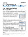
User Manual
Event sequencer & USB valve driver
20069101
19 september 2006
Electronics Group,
Faculty of Sciences
Vrije Universiteit Amsterdam, the Netherlands
Phone : +31-20-5987971
Fax
: +31-20-5987899
Project ID :
Filename : User Manual
Pages
: 15
Last save : Arnoud
Email
: [email protected]
Web
: http://www.few.vu.nl/~elec
User Manualv2.doc
i
Table of contents
1
2
3
4
5
Safety instructions....................................................................................................................1
General information .................................................................................................................2
User guide, connecting the hardware ......................................................................................4
User guide, starting the software .............................................................................................5
Event sequencer ......................................................................................................................6
5.1 Event sequencer screen sections........................................................................................6
5.2 Manual mode .......................................................................................................................6
5.3 The sequence mode............................................................................................................7
5.3.2 Trigger and reset.........................................................................................................8
5.4 The configuration window................................................................................................. 10
5.4.1 Portnames................................................................................................................ 10
5.4.2 Eventnames ............................................................................................................. 11
5.5 Sequence editor................................................................................................................ 12
5.5.1 Inserting and changing methods.............................................................................. 12
5.6 Method editor.................................................................................................................... 13
Electronics Group
Vrije Universiteit Amsterdam, Faculty of Sciences
User Manualv2.doc
1
1 Safety instructions
Precautions
Hazardous voltages exist in this apparatus. Besides the regular safety precautions the following
should be observed when working with this unit:
1. When power is required, the unit should be plugged into an outlet with a properly
grounded receptacle. The use of two prong plug adapters is not recommended.
2. The use of extension cords may compromise the safety of the operator and is not
recommended.
3. Ensure that the fuses installed in the unit are of the correct rating.
4. A damaged power cord or plug may constitute a shock or fire hazard. Do not allow
continued operation of the unit until the damaged cord or plug has been replaced.
5. Ensure that none of the ventilation openings in the unit are blocked. Excessive heat build
up in the unit may cause failures.
Caution: Do not exceed maximum allowable mains input voltage.
Safety check has been done following the NEN-EN 50110-1 and NEN 3140.
Electronics Group
Vrije Universiteit Amsterdam, Faculty of Sciences
User Manualv2.doc
2
2 General information
This document describes the USB valve driver designed for VICI valves and the include software
Event sequencer v1.0 (220806).
Fig. 2a, Front side of the USB valve driver
Fig. 2b, Back side of the USB valve driver
At the front of the USB valve driver there are 5 LEDs. The first LED will illuminate when the
software has given a reset. The LED will stop illuminating when the USB connection is broken. So
it just an indicator that the USB connection is ok.
The 4 LEDs below the first one, will illuminate when there is power regarding the valve which the
LED represents.
At the front there are also 4 connectors. Two connectors for the 6 position type valve (VICI
EMTMA-CE, see fig 2c) and two connectors for the 2 positions type valve (VICI EHMA, see fig.
2d).
Electronics Group
Vrije Universiteit Amsterdam, Faculty of Sciences
User Manualv2.doc
Fig. 2c, A 6 positions valve from VICI (EMTMA-CE)
3
Fig. 2d, A 2 positions valve from VICI (EHMA)
At the back of the USB valve driver there are 4 power connectors. Please connect the power
supplies supplied with the valve driver (GlobTek TR9CI3200LCP-Y-2 24V, 2.1A).
Fig. 2e, One of the 4 power supplies (GlobTek TR9Ci3200LCP-Y-2)
At the back of the USB valve driver there are also 2 input connectors present. A trigger input and
a reset input. They both are (falling edge) TTL driven.
The latest connector mounted on the back of the USB valve driver, is the USB connector.
The software consists of a Java program called event_valve.jar
In order to run the Java program, a Java run-time environment has to be installed
(www.sun.com). Also it is needed to install the NI-DAQ device drives 8.3 (from national)
Electronics Group
Vrije Universiteit Amsterdam, Faculty of Sciences
User Manualv2.doc
4
3 User guide, connecting the hardware
The connection of the USB valve driver is simple and straight forward.
•
•
•
•
Connect the valves
Connect the reset and the trigger inputs
Connect the power supplies
Connect the USB connector
Note: when inserting the USB connector, the computer will respond with a program called
NI device monitor. Just cancel the appearing dialog messages.
Electronics Group
Vrije Universiteit Amsterdam, Faculty of Sciences
User Manualv2.doc
5
4 User guide, starting the software
Startup the Java program (event_valve.jar, see fig 4a).
Fig. 4a, A screen dump of the Event sequencer “ event.jar”
At startup the latest configuration will be loaded. When an other configuration is needed, please
load an other configuration by entering the Configuration editor (see chapter 5.4).
Electronics Group
Vrije Universiteit Amsterdam, Faculty of Sciences
User Manualv2.doc
6
5 Event sequencer
The program Event sequencer will send data to the USB valve driver so that all the valves are set
in the position the user wants.
5.1 Event sequencer screen sections
The Event sequencer screen has several screen sections.
Fig. 5a The screen of the Event sequencer with its sections
The Event sequencer screen has a valve position section. In this section the user can see the
current position of the valves. The second section is a list of events (a method), and a list of
methods (a sequence). See chapter 5.3 about events, methods and sequences. There is also a
description section. Here you can read some information during the run of the program. The last
section of the screen is the button section. Read further on for the functions of the buttons.
5.2 Manual mode
Electronics Group
Vrije Universiteit Amsterdam, Faculty of Sciences
User Manualv2.doc
7
The Event sequencer has two modes. The sequence mode and the manual mode. The manual
mode can be started to select the button manual. (A description about the sequence mode can be
seen in chapter 5.3)
When the manual mode is started, the Manual control window will appear. The Manual control
window has a series of radio buttons divided into 4 groups. Each group represents a valve. By
pressing a radio button, a valve will go to the position selected by the radio button. The button of
the current position of valve will light up, not the selected position. (So when pressing position
2, position 2 will light up when the valve has reached position 2).
Fig. 5b The manual control window
Each radio button has a name, called portname. These portnames can be altered in the
Portnames editor (see chapter 5.4.1).
The manual control window is ideal for testing purposes.
Note, the sequence mode is always active.
5.3 The sequence mode
The Event sequencer will send data to the valves when it receives a trigger. The data which has
to be send can be altered, saved and loaded by the user (in the Configuration editor see chapter
5.4). The data is separated into events, methods and a sequence.
5.3.1.1 An event
The data sended to the USB valve driver is called an event. An event consists of the positions of
two 6 position valves and two 2 position valves. Furthermore it consists of a description. The
description will be displayed when the data is send to the valves.
5.3.1.2 A method
A series of events is called a method. A description can be added to a method. When the method
is used, the description will be displayed. A method can consists of different, but also duplicate
events.
5.3.1.3 The sequence
Electronics Group
Vrije Universiteit Amsterdam, Faculty of Sciences
User Manualv2.doc
8
The methods are grouped and put in a list. Such a list is called a sequence. Sometimes it is
needed to run a method more than once. To do this, it is possible to change the cycle wanted of
each method. The sequence can hold different, but also duplicate methods.
5.3.2 Trigger and reset
At the start, the first method will be opened. In this method there are a couple of events. When a
trigger is received the first event of this method will be sended to the valves. When a second
trigger is received the second event is sended. So at each next trigger, the next event will be
sended.
When the last event (of the method) is reached, the method will start again, or a new method will
be opened, depending on the amount of cycles the method has to run. Finally the last event of
the last method will be reached. At this stage the program will just halt, until a reset.
When resetting before reaching the last event, the next Event will be the first event. See the
flowchart in fig 5c.
Electronics Group
Vrije Universiteit Amsterdam, Faculty of Sciences
User Manualv2.doc
9
Fig. 5c The flowchart of the Event Sequencer
Electronics Group
Vrije Universiteit Amsterdam, Faculty of Sciences
User Manualv2.doc
10
5.4 The configuration window
The Configuration window can be started by pressing the configuration button in Event sequencer
window.
Fig. 5d The configuration window
In the Configuration window you can load an other configuration. This can be done just by
pressing the load conf button. At default, the latest used configuration will be loaded at the start of
the Event sequencer. It also possible to save the a configuration. This can be done by pressing
the save conf button.
A configuration consists of 3 parts. A sequence, (which is a list of methods, which are lists of
events), eventnames and portnames.
5.4.1 Portnames
Portnames are aliases used to represent the port number of a valve. Instead of a port number, it
is possible to use a substance name or such. The aliases are used at the valve representation at
the Event sequencer screen, and in the Manual control window. The portnames can be altered in
the Portname editor. The Portname editor window will be opened when the editor button on the
section of portnames at the Configuration window is being pressed.
Fig. 5e The Portname editor window
Electronics Group
Vrije Universiteit Amsterdam, Faculty of Sciences
User Manualv2.doc
11
Fig. 5f a portnames being used, at the screen Event sequencer and in the manalcontrol window
As can be seen in the Portname editor window, the portnames can be saved and loaded. It is
also possible to load portnames directly by pressing the portnames load button.
5.4.2 Eventnames
Instead of using positions of the valves throughout the whole program, eventnames are used. So
instead of “position 2” an “action” as a name can be used. Eventnames are just aliases in the
whole program.
The Eventnames editor window is opened by pressing the editor button at the eventnames
section in the Configuration editor window. Just as the port names, you are able to alter, load and
save the eventnames.
Fig. 5g Event names being used, at Screen event sequence
Electronics Group
Vrije Universiteit Amsterdam, Faculty of Sciences
User Manualv2.doc
12
5.5 Sequence editor
The most important part of the Configuration editor is the Sequence editor. In the Sequence
editor you can alter the data which is going to be sended to the valves.
By pressing the editor button at the sequence level in the Configuration editor, you can open the
Sequence editor.
Fig. 5h The sequence editor
At the Sequence editor you can insert, change, and delete methods. Also you can load and save
the sequence (the list with methods).
5.5.1 Inserting and changing methods
By pressing the insert button, you will be inserting a method entry. By pressing the change button
you will be able to change the method entry.
Fig. 5i Inserting or changing a method
A window will appear when the insert or change button is pressed. At the top of the window, is a
button with the method name. You can select a other method by pressing this button. At the field
cycle you can enter how much cycles you want the Method to run. The default cycle is always 1.
At the comment field you can enter a comment.
Electronics Group
Vrije Universiteit Amsterdam, Faculty of Sciences
User Manualv2.doc
13
5.6 Method editor
The methods can be edited in the Pre Method editor. The Pre Method editor can be opened by
pressing the method editor button in de sequence editor.
Fig. 5j The pre method editor
You can select if you want to insert, change or delete a method. By selecting a method and
pressing delete method the method will be deleted.
By pressing new or change the Method editor will open. In this editor the actual method can be
changed. The method editor can also being opened direct from the main window. This will allow
to change the active method directly.
Electronics Group
Vrije Universiteit Amsterdam, Faculty of Sciences
User Manualv2.doc
14
Fig. 5k The method editor
The event names are displayed at the top of the Method editor. They are just a reminder which
position has which alias.
By pressing the insert event button a window will be opened to insert an event into the method
list.
Fig .5l Inserting an event
By pressing the arrow next to the text fields, a popup menu will appear. Here you can select
which position has to be send to the valve. Instead of position, eventnames are has to be chosen.
Changing is the same as inserting. Just select the wanted event name.
Fig. 5m Changing an event
To delete a event out of the method list, just select the event and press the delete button in the
method editor.
Electronics Group
Vrije Universiteit Amsterdam, Faculty of Sciences