1
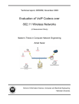
Technical Note 413 Valco Instruments Co. Inc. Two Position Microelectric Valve Actuator (Control module serial numbers starting with EM2C)* The microelectric actuator consists of a control module, a stepper motor/gearbox assembly, a manual controller (use is optional), a universal AC input (100-240 VAC, 50-60 Hz) to 24 VDC power supply, and the interconnecting cables. The actuator is self-adjusting from 30° to 90° – no valve alignment is necessary. Once a valve is installed by tightening the clamp screw, the actuator senses the positive stops within the valve and memorizes them in the first four moves. The time it takes a valve to cycle from Position A to Position B depends on the amount of rotation involved. To determine the number of degrees in the angle of rotation, divide 360° by the number of ports in the valve. Then consult the table at right. Installation and Use Getting Started Figure 1 on the next page shows how to connect the various actuator components. There are four connectors on the control module, keyed and sized to p revent incorrect connection. Cable and Connector Functions Input power (20-30 VDC, with 24-28 VDC preferred) is supplied through a coaxial connector: the inner pin is + voltage and the outer pin is ground. The average DC current requirement is 2.5 amps. Standby current draw is 60 milliamps. The actuator should not share a power supply with other noise-sensitive electronics, as the high current draw can cause problems. inner +20-30 VDC power outer Ground Motor driver output is through the five-pin connector: pins 1, 2, 4, and 5 carry the stepper motor phase drive signals. Pin 3 is grounded and tied to the cable shield to reduce electrical noise. 1 Phase B 2 Phase B 3 Ground A three-pin connector is used for the RS-232 interface: pin 1 is ground, pin 2 is transmit to the host computer, and pin 3 is receive from the host. (A discussion on serial control of the actuator starts on page 3.) 4 Phase A 5 Phase A The ten-pin connector is for the manual controller or for digital input/output signals; the actuator can be controlled by either or both. The manual controller has a through port, so an additional cable can provide simultaneous control by an external system. (Digital control of the actuator is discussed on page 3.) * Serial numbers are on the underside of the control module. (Figure 2) Actuators of this series, obsoleted in 2010, are further identified by a metallic control module housing. If your actuator control module has a plastic housing and a serial number starting with E2CA, please refer to Technical Note 421. 1 POWER SUPPLY P/N PS24VDC-CE TO 110 OR 220 VAC (User must supply other line cord configurations) LINE CORD (IEC-320) P/N I-W-17600 TO EXTERNAL CONTROL SYSTEM OPTIONAL INPUT POWER CABLE P/N I-22535-CE BLACK / WHITE STRIPE +24-28 VDC GND BLACK DIGITAL INPUT/ OUTPUT CABLE P/N I-22537 MOTOR DRIVER OUTPUT CABLE P/N I-22645 MOTOR/GEARBOX ASSEMBLY P/N EQMA (Highest speed) EHMA (High speed and Medium torque) EDMA (High torque ETMA (Highest torque) PIN 1 MANUAL CONTROLLER (Use optional) P/N I-22689 MOUNTING BRACKET P/N I-22596 PIN 1 Valco Instruments Co. Inc. POSITION POSITION A B 2 POSITION ACTUATOR CONTROL MODULE CLAMP RING PIN 1 CLAMP SCREW POSITION INDICATOR LIGHTS P/N: EQCA-CE (Highest speed) EHCA-CE (High speed) EPCA-CE (Medium torque) EDCA-CE (High torque) ETCA-CE (Highest torque) POSITION A B PIN 1 MANUAL CONTROLLER CABLE P/N I-22537-01 TO COMPUTER OPTIONAL SERIAL PORT (RS-232) CABLE P/N I-22697 DB-9 CONNECTOR (FEMALE) Figure 1: Actuator and controller connections 2 PIN 1 Mounting OK OK The actuator should be oriented so that any potential leakage of liquid from the valve or fittings flows away from rather than into the actuator. (below) Figure 2 provides the mounting dimensions for the stepper motor/gearbox assembly. 3.4" for EH 4.4" for ET 1.95" 3.24" 1.375" 2.7" 2.2" .9" 3.9" SERIAL NUMBER TAG 3.1" .7" .973" 1" 1" .75" 8-32 MOUNTING HOLES* CONTROL MODULE The length of the 8-32 screws used for panel mounting is not critical, as long as they extend at least 1/4" into the actuator casting. Initialization Figure 2 Any time a valve is removed and reinstalled, the actuator must be initialized by following these steps: 1. Cycle the actuator twice with no valve, or with either end of the motor driver output cable unplugged. 2. Plug the cable back in, or put the valve back in the clamp ring. Orient the valve as desired and tighten the clamp screw. For the next few cycles the actuator will move at half its normal speed while it looks for the valve stops. Once it determines the proper stroke, the actuator will return to normal speed. If you don’t hear a change in speed, make sure that the clamp screw is tight. Digital Control of the Actuator Digital I/O Cable Digital Communication Protocol Pin # Pins 1 and 2 provide ground and +5 volt outputs, respectively; pins 3 and 4 are TTL outputs for Position A and Position B, and are considered asserted at 0 volts and deasserted at 5 volts. (This is sometimes referred to as “negative true logic”.) Pins 5 and 6 are digital inputs for switching to Position A and Position B. They can be driven either by 5 volt TTL/CMOS logic or by contact closure to ground (Pin 1). Isolated contact closure outputs are available at Pins 7 and 8 for Position A and Pins 9 and 10 for Position B. If there is a positioning error due to valve sticking, clamp ring slippage, etc., the output is set to “0” (all lines high for a negative true output). Signal Description 1 Ground 2 +5 VDC 3 Position A output 4 Position B output 5 Position A input 6 Position B input 7 Position A relay contact output 8 Position A relay contact output 9 Position B relay contact output 10 Position B relay contact output Input Modes Two input mode options are provided to expand the control flexibility of the actuator. Mode 1 In mode 1 (default) the digital inputs are set to be compatible with the standard Valco AC actuator. Asserting input pin 5 causes the actuator to go to Position A, and asserting input pin 6 sends it to 3 Position B. Operation in this mode requires two relays, as shown in the illustration at right. Relays should be asserted (turned on) for a minimum of 30 msec and deasserted (turned off) for a minimum of 30 msec before the next assertion. Mode 2 Operation in this mode requires one relay. In mode 2, asserting pin 5 causes the actuator to toggle from the current to the opposite position. Asserting pin 6 causes the actuator to toggle to the opposite position, delay for a preset period of time (the default is 100 ms), and toggle back to the original position. Mode 1 PIN 1 RELAY 1 PIN 5 PIN 6 RELAY 2 CABLE (I-22537) Mode 2 Toggle setup (A B A) PIN 1 RELAY PIN 5 CABLE (I-22537) Delay setup (A B) Mode Setup To set the actuator mode, connect it to an RS-232 serial port as RELAY described in the section below, Establishing Serial Communications. To see the current setting, enter the SM CABLE (I-22537) command as shown in the Serial Commands chart on page 5. To change the mode, enter SMn, where n is 1 or 2. The DT command displays the current delay time setting. This setting can be changed with the DTn command, where n is the desired time from 0 to 65,000 milliseconds. PIN 1 PIN 6 Mode settings are saved when the power is off. Serial Control of the Actuator Establishing Serial Communications Items required: • Valco cable assembly I-22697 or equivalent • Terminal emulation or communication software such as QModem, ProComm, or Windows® Terminal or HyperTerminal, running on a PC-compatible computer 1. Connect the I-22697 cable to the actuator as indicated in Figure 1, and set the serial port at 9600 baud, no parity, 8 data bits, 1 stop bit, no hardware or software handshaking. 2. With the software running, check the bi-directional communication link between the keyboard/monitor of the computer and the serial port by typing VR<enter>. If the link is functioning and an actuator ID has not been set, a message similar to the following will appear on your monitor, giving the program number and date of the actuator firmware. I-PD-ETX88RXX (XX = revision number) 2 - Aug - 99 If there is no response, it is possible that the ID has already been set. To force a response from a device with an unknown ID, type *VR<enter>. The asterisk is a substitute ID wild card which will elicit a response from all devices on line, no matter what their ID is. Programmer’s note: To permit multiple actuators to share the same computer serial port, the actuator serial port output is deactivated when not in use. At the beginning of a message the first character transmitted is sometimes lost due to a framing error. To avoid this, a NULL character (zero value byte) is sent at the beginning of each message. Most terminal programs will ignore the NULL character, but custom software may require a character trap to delete it. Serial Communication Protocol Serial Port (RS-232) Cable Serial communication is based on an ASCII string protocol. Carriage return (OD hex) characters parse the communications by defining the end of each command. Line feed characters (OA hex) are ignored. A three-pin connector is used for the RS-232 interface: pin assignments are indicated at right. Software flow control (Xon/Xoff) and hardware handshaking are not supported. 4 Pin # Signal Description 1 Ground 2 Transmit to host 3 Receive from host Serial Commands CP<enter> Displays the current actuator position CW<enter> Sends the actuator to Position A CC<enter> Sends the actuator to Position B GOn<enter> Sends the actuator to Position n, where n is A or B TO<enter> Toggles the actuator to the opposite position TT<enter> Toggles the actuator to the opposite position, waits a preset delay time, then rotates back to the original position. ID<enter> Displays the current device ID setting IDn<enter> Sets the device ID to value n, from 0 to 9 NOTE: When the ID feature is enabled, all commands to the device must be prefaced by the ID number. Entering ID* disables this feature (discussed below.) ID*<enter> Clears the ID variable SB<enter> Displays the current baud rate SBnnnn<enter> Sets the baud rate to 1200, 2400, 4800, 9600 (default), 14400, 19200, 28800, or 38400. The parity setting, number of data bits, and number of stop bits cannot be changed. (See section entitled Setting a New Baud Rate on the next page) SOnnnn<enter> Turns off the position outputs after a delay, set in milliseconds to the closest 5 ms interval, from 0 to 30,000 ms. The outputs are always on (SO=0) by default. SM<enter> Displays the current digital input mode (See section entitled Digital Control of the Actuator, subhead Input Modes) SMn<enter> Sets the digital input mode to Mode n, where n is 1 or 2 DT<enter> Displays the current delay time in milliseconds DTn<enter> Sets the delay time from 0 to 65,000 milliseconds NOTE: The total delay time equals n = 2 milliseconds VR<enter> Displays the part number and date of the firmware /?<enter> Displays list of valid commands IN<enter> Starts a re-inialization sequence With the software-settable device “ID” feature enabled, the serial port output (transmit line) of the actuator is disabled (high impedance). Thus, as many as ten actuators can be controlled from a single host serial port for a temporary multidrop application. For permanent multidrop applications, the RS-485 option is the factory-recomended solution. The table above describes and explains all the commands available. Using the Device ID Feature Actuators are shipped from the factory with this feature disabled. When it’s enabled, the actuator responds only to commands which begin with the correct ID prefix, allowing up to 10 actuators to be controlled from one serial port. A single command can be broadcast to all actuators by using an asterisk (*) as the command prefix. Note: Any broadcast command which elicits a response from the serial port (such as *VR or *ID1) will receive a combined and unintelligible response. 5 To set the ID of an actuator, connect it to an RS-232 serial port as shown in Figure 1 on page 2. Caution: When installing or replacing actuators on a shared serial port, make sure that no two devices have been set to the same ID number. 1. Remove all of the actuators from the serial daisy chain except the one for which you are setting the ID. 2. Type VR <enter>. You should get a response giving the firmware version, indicating that serial communication with the actuator is established. If there is no response, type *VR<enter> to see if the ID is already set. If there is still no response, check the cabling and connections. 3. To set an ID, type IDn<enter>, where n is the new ID, from 0 to 9. To change an ID, type i IDn<enter>, where i is the current ID and n is the new ID. To disable the ID feature, type i ID*<enter>, where i is the current ID. Setting a New Baud Rate To permanently set a new baud rate for the actuator: 1. Establish communications with the actuator at the current baud rate. 2. Issue the command SBnnnn to temporarily change the baud rate to the desired rate. If the power goes down at this point, the baud rate will revert to the last permanent setting. 3. Change the host computer to the same baud rate just set in the actuator, and verify that you can establish communications. 4. Re-issue the same SBnnnn command you did previously (in Step 2), and the current baud will be made permanent. RS-485 Option JUMPERS 1 AND 2 Software The RS-485 option involves three minor software adaptations to the RS-232 protocol. The first is that the ID range is extended to include the characters “A” through “Z”, with upper and lower cases treated as the same ID. The second Figure 3: Control module, change is that the ID is required (either numbers from 0 to 9 or letters from A to Z), and must be included in all commands. The factory-set default ID for all devices is “Z”. The third adaptation is that all commands must include a forward slash [/] as the start-ofmessage character. Hardware The RS-485 hardware includes two 3-pin connectors (Figure 3) used as in/out connectors for easy daisy-chaining of additional devices. Wired in parallel, the signal assignments are as follows: Pin 1 is Ground, Pin 2 is Phase B, and Pin 3 is Phase A. The four male pins in a vertical row to the left of these connectors are jumper headers, used to add or remove terminating resistors from the communication lines. The top two and the bottom two should be jumpered when term-ination is required. The RS-485 hardware specifications require termination at each end of the communication line, so in a daisy-chaining application the jumpers should be removed from all the intermediate devices. The RS-485 port on the host computer or controlling device generally includes terminating resistors, so only the actuator on the end of the communication string needs to have the jumpers installed. North America, South America, and Australia/Oceania contact: ® Valco Instruments Co. Inc. P.O. Box 55603 Houston, TX 77255 Sales: (800) 367-8424 Tech: (713) 688-9345 Fax: (713) 688-8106 [email protected] Europe, Asia, and Africa contact: ® TN-413 Rev 1/11 VICI AG International Parkstrasse 2 CH-6214 Schenkon Switzerland Phone: +41 41 925 6200 Fax: +41 41 925 6201 [email protected] Cheminert® and VICI® are registered trademarks of Valco Instruments Co. Inc. and VICI AG