1
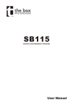
definition install manualv2:Layout 1
9/2/09
13:16
Page 1
INSTALL RANGE USER MANUAL
definition install manualv2:Layout 1
9/2/09
CONTENTS
2
SAFETY INSTRUCTIONS
3
PRODUCT IDENTIFICATION
3
ACCESSORIES
4
INSTALLATION GUIDELINES
5-6
PRODUCT DIMENSIONS
7-8
TECHNICAL SPECIFICATIONS
7
FULL RANGE models
8
SUBWOOFER models
9
10
1
WARRANTY STATEMENT
DECLARATION OF CONFORMITY
13:16
Page 1
definition install manualv2:Layout 1
9/2/09
13:16
Page 2
SAFETY INSTRUCTIONS
1. Read these instructions.
2. Keep these instructions.
3. Heed all warnings.
4. Follow all instructions.
5. The user is responsible for fixing the hardware to the surface to ensure safe operation. The fixings must support the
weight of the product – please consult the manual’s specification page for the appropriate weights. Please consult the
relevant construction codes in your region for further information on suitable hardware fixing methods.
6. Some regional construction codes require the use of a secondary method of securing loudspeakers to surfaces to
provide security of a back-up support. A secondary support line should be attached from the safety loop on the rear of
the product to a source point on the wall. Please consult the relevant construction codes in your region.
7. Tannoy will not be held accountable for any damage caused by incorrect installation.
2
definition install manualv2:Layout 1
9/2/09
13:16
Page 3
PRODUCT IDENTIFICATION
FULL RANGE MODELS
Definition DC6i
Definition DC8i
Definition DC12i
ACCESSORIES
WALL BRACKET
(only supplied with full range models)
3
SUBWOOFER MODELS
Definition sub 12i
Definition sub 15i
definition install manualv2:Layout 1
9/2/09
13:16
Page 4
INSTALLATION GUIDELINES
SURFACE MOUNTING THE LOUDSPEAKERS:
1. Lay the loudspeaker cable from the amplifier
to the location where you intend to surface
mount the loudspeaker.
2. Terminate the loudspeaker cable with 4mm
connectors or spade connectors.
Connect the loudspeaker to the approipriate
amplifer channel.
The positive terminal on the amplifier channel
(marked + or coloured red) must be connected
to the positive terminal on the loudspeaker
(coloured red).
Fig 1.
The negative terminal on the amplifier channel
(marked - or coloured black) must be connected
to the negative terminal on the loudspeaker
(coloured black).
3. Attach the bracket plate to the wall using
appropriate fixings (Please consult the safety
notes section of this user manual). See Fig 1.
Fig 2.
4. Offer the loudspeaker up to the bracket.
The speaker can be installed either landscape
or portrait.
5. Attach the loudspeaker to the bracket by
slotting the two bracket posts into the
appropriate bracket insert points on the rear of
the loudspeaker then lowering the loudspeaker
down to allow it to lock onto the bracket.
See Fig 2.
4
definition install manualv2:Layout 1
9/2/09
13:16
Page 5
PRODUCT DIMENSIONS
DEFINITION DC6i
250.0
[9.84"]
214.6
[8.45"]
334.0
[13.15"]
DEFINITION DC8i
294.0
[11.57"]
215.0
[8.46"]
394.0
[15.51"]
DEFINITION DC12i
410.0
[16.14"]
550.0
[21.65"]
5
255.0
[10.04"]
definition install manualv2:Layout 1
9/2/09
13:16
Page 6
DEFINITION SUB12i
370.0
[14.57"]
355.0
[13.98"]
435.0
[17.13"]
DEFINITION SUB15i
460.0
[18.11"]
430.0
[16.93"]
525.0
[20.67"]
6
definition install manualv2:Layout 1
9/2/09
13:16
Page 7
TECHNICAL SPECIFICATIONS FULL RANGE MODELS
SYSTEM
DC6i
DC8i
DC12i
Frequency Response (-3dB) (1)
85Hz - 35kHz
80Hz - 35kHz
67Hz - 25kHz
Frequency Range (-10dB) (1)
70Hz - 45kHz
62Hz - 45kHz
50Hz - 38kHz
90dB (1W = 2.83V for 8 ohms)
92dB (1W = 2.83V for 8 ohms)
97dB (1W = 2.83V for 8 ohms)
Dispersion (-6dB)
90 degrees conical
90 degrees conical
90 degrees conical
Directivity Factor (Q)
4.5 averaged 1kHz to 10kHz
5.7 averaged 1kHz to 10kHz
6.0 averaged 1kHz to 10kHz
Directivity Index (Di)
6.4 averaged 1kHz to 10kHz
7.0 averaged 1kHz to 10kHz
7.4 averaged 1kHz to 10kHz
System Sensitivity (1W @1m)
Power Handling
(2)
(2)
Average
100W
130W
200W
Programme
200W
260W
400W
Peak (10ms)
400W
520W
800W
200W @ 8 Ohms
260W @ 8 Ohms
400W @ 8 Ohms
Average
110dB
113dB
120dB
Peak
116dB
119dB
126dB
Recommended Amplifier Power
Rated Maximum SPL(2)
Nominal Impedance
8 Ohms
8 Ohms
8 Ohms
Driver Complement
1 x 150mm (6.00”) constant
1 x 200mm (8.00”) constant
1 x 300mm (12.00”) constant
directivity Dual Concentric™
directivity Dual Concentric™
directivity Dual Concentric™
Passive 1.6kHz with dynamic HF
Passive 1.7kHz with dynamic HF
Passive 1.4kHz with dynamic HF
protection
protection
protection
Crossover
Distortion 10% Full Power
(8.94V) 2nd Harmonic 3rd Harmonic
(10.2V) 2nd Harmonic 3rd Harmonic
(12.65V) 2nd Harmonic 3rd Harmonic
250Hz
2.40%
0.46%
0.40%
0.35%
0.53%
1kHz
0.20%
0.53%
0.28%
0.66%
2.36%
1.88%
10kHz
1.19%
0.19%
1.50%
0.35%
2.68%
0.16%
Distortion 1% Full Power
(2.83V) 2nd Harmonic 3rd Harmonic
(3.22V) 2nd Harmonic 3rd Harmonic
(4V) 2nd Harmonic
0.35%
3rd Harmonic
250Hz
0.48%
0.37%
0.11%
0.15%
0.17%
0.09%
1kHz
0.01%
0.24%
0.12%
0.34%
0.52%
0.99%
10kHz
0.46%
0.07%
0.51%
0.17%
0.96%
0.02%
CONSTRUCTION
Enclosure
MDF, vented and internally braced
Finish
Textured black
2 x 4mm Gold Plated binding posts
Fittings
8 x M10 bracket inserts, 4 x wallplate keyhole fixings, allowing landscape or portrait mounting orientation, 1 x Wall plate
Dimensions (H x W x D)
334mm x 250mm x 214mm
(13.5” x 9.84” x 8.45”)
394mm x 294mm x 215mm
(15.51” x 11.57” x 8.46”)
550mm x 410mm x 255mm
(21.65” x 16.14” x 10.04”)
Weight
7kg (15.4lbs)
9.5kg (20.9 lbs)
20kg (44 lbs)
Notes
(1)
Average over stated bandwidth. Measured on axis in half space.
(2)
Long term power handling capacity as defined in EIA standard RS-426A.
A full range of measurements, performance data, and Ease™ Data can be downloaded from www.tannoy.com. Tannoy operates a policy of continuous research and development.
The introduction of new materials or manufacturing methods will always equal or exceed the published specifications, which Tannoy reserves the right to alter without prior notification.
7
definition install manualv2:Layout 1
9/2/09
13:16
Page 8
TECHNICAL SPECIFICATIONS SUBWOOFER MODELS
SYSTEM
SUB12i
SUB15i
System Type
Subwoofer - Direct Radiating
Subwoofer - Direct Radiating
48Hz
47Hz
38Hz
36Hz
Frequency Response (-3dB) (1)
Frequency Range (-10dB)
(1)
System Sensitivity (1W @1m)
(1)
94dB (1W = 2.83V for 8 ohms)
96dB (1W = 2.83V for 8 ohms)
Average
400W
600W
Programme
800W
1200W
Peak (10ms)
1600W
2400W
400 - 800W @ 8 Ohms
600 - 1200W @ 8 Ohms
Average
120dB
124dB
Peak
126dB
130dB
Nominal Impedance
8 Ohms
8 Ohms
Driver Complement
1 x 300mm (12.00”) Bass driver
1 x 380mm (15.00”) Bass driver
Recommended Crossover
80Hz - 300Hz, 24dB/octave
70Hz - 300Hz, 24dB/octave
Recommended High-pass filter
40Hz, 24dB/octave
35Hz, 24dB/octave
(17.9V) 2nd Harmonic 3rd Harmonic
(21.9V) 2nd Harmonic 3rd Harmonic
Power Handling (2)
Recommended Amplifier Power
Rated Maximum SPL(2)
Distortion 10% Full Power
40Hz
0.28%
2.26%
0.83%
0.68%
100Hz
0.29%
0.60%
0.23%
0.44%
Distortion 1% Full Power
(5.9V) 2nd Harmonic 3rd Harmonic
(6.9V) 2nd Harmonic 3rd Harmonic
40Hz
2.00%
0.15%
0.44%
0.28%
100Hz
0.009%
0.124%
0.15%
0.15%
CONSTRUCTION
Front 36mm (13/8") other panels 15mm (5/8") MDF internally braced.
Enclosure
Volume
38 litres
76 litres
Finish
Black paint
Connectors
Fittings
2 x 4mm Gold Plated binding posts
with screw terminals and "loop through" facility
8 x M10 inserts, 4 x Rubber feet (not fitted)
Dimensions (H x W x D)
435mm x 370mm x 355mm
(17.1” x 14.6”x 14.0”)
525mm x 460mm x 430mm
(20.7” x 18.1” x 16.9”)
Weight
21kg (46.3lbs)
30kg (66.1lbs)
Notes
(1)
Measured on axis in half space.
(2)
Unweighted pink noise input measured in an IEC baffle in an anechonic chamber. If the loudspeaker is installed in a false wall near a corner ( /2) an increase of 6dB in sensitivity and
maximum SPL can be realised.
A full range of measurements, performance data, and Ease™ Data can be downloaded from www.tannoy.com. Tannoy operates a policy of continuous research and development.
The introduction of new materials or manufacturing methods will always equal or exceed the published specifications, which Tannoy reserves the right to alter without prior notification.
8
definition install manualv2:Layout 1
9/2/09
13:16
Page 9
WARRANTY STATEMENT
No maintenance of the Definition loudspeaker is necessary.
All of our products have been produced and tested with care and precision to give first-class service.
All passive components are guaranteed for a period of five years from the date of purchase from an authorised Tannoy dealer
subject to the absence or evidence of misuse, overload, or accidental damage.
All active and electronic components are guaranteed for a period of one year from the date of purchase from an authorised
Tannoy dealer subject to the absence of, or evidence of, misuse, overload or accidental damage.
If at any time during this warranty period the equipment proves to be defective for any reason other than accident, misuse,
neglect, unauthorised modification or fair wear and tear, we will repair any such manufacturing defect or, at our option,
replace it without charge for labour, parts or return carriage.
If you suspect a problem with a Tannoy product then, in the first instance, discuss it with your Tannoy dealer. If you require
further assistance then we ask that you deal directly with your local Tannoy distributor. If you cannot locate your distributor
please contact Customer Services, Tannoy Ltd at the address given below.
Customer Services, Tannoy Ltd., Rosehall Industrial Estate, Coatbridge, Strathclyde ML5 4TF, Scotland
Telephone:
Fax:
E-mail:
01236 420199
(National)
+44 1236 420199
(International)
01236 428230
(National)
+44 1236 428230
(International)
[email protected]
DO NOT SHIP ANY PRODUCT TO TANNOY WITHOUT PREVIOUS AUTHORISATION
Our policy commits us to incorporating improvements to our products through continuous research
and development. Please confirm current specifications for critical applications with your supplier.
9
definition install manualv2:Layout 1
9/2/09
13:16
Page 10
DECLARATION OF CONFORMITY
The following apparatus is manufactured in the UK at Tannoy Ltd of Rosehall Industrial Estate, Coatbridge, Scotland,
ML5 4TF and conform(s) to the protection requirements of the European Electromagnetic Compatibility Standards
and Directives relevant to Domestic Electrical Equipment. The apparatus is designed and constructed such that
electromagnetic disturbances generated do not exceed levels allowing radio and telecommunications equipment
and other apparatus to operate as intended, and, the apparatus has an adequate level of intrinsic immunity to
electromagnetic disturbance to enable operation as specified and intended.
Details of the Apparatus:
Associated Technical File:
Applicable Standards:
Signed:
Position:
Tannoy Contractor Loudspeaker
Model Number: Definition
EMCi6
EN 50081-1 Emission
EN 50082-1 Immunity
Director of Engineering (Professional)
Date: 07th Feb. 07
10
definition install manualv2:Layout 1
9/2/09
13:16
Page 11
REVISION DATE: Aug ‘07
T: 00 44 (0) 1236 420199
T: 00 1 (519) 745 1158
T: 00 49 (180) 1111 881
T: 00 33 (0)1 7036 7473
E: [email protected]
E: [email protected]
E: [email protected]
E: [email protected]
Tannoy adopts a policy of continuous improvement and product specification is subject to change.
6481 0500
Tannoy United Kingdom
Tannoy North America
Tannoy Deutschland
Tannoy France