1
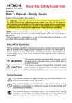
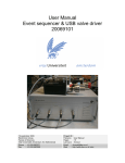
Technical Note 421 Valco Instruments Co. Inc. Two Position Microelectric Valve Actuator (Control module serial numbers starting with E2CA)* Introduction Description The two position microelectric actuator consists of a control module, a stepper motor/gearbox assembly, a manual controller (use is optional), a universal AC input (100-240 VAC, 50-60 Hz) to 24 VDC power supply, and the interconnecting cables. The actuator is for use with all Valco and Cheminert two position valves with stops, toggling them back and forth between Positions A and B and outputting a position indication at the end of each move. (Position A is the counterclockwise position as seen when facing the output shaft of the motor; Position B is clockwise.) The actuator is self-adjusting—no manual valve alignment is necessary. The end points of the valve travel are automatically located during a user-prompted initialization sequence which must be run each time a valve is mounted on the motor assembly. (Refer to page 4.) Actuator torque and speed are functions of the particular gearbox/motor/controller combination, which is designated as Model EQ, EH, EP, ED, ET, or EB in order of increasing torque/ decreasing speed. Models EQ, EH, ED, and ET have unique gearboxes; Models EP and EB have EH and ET gearboxs, respectively, with the motor traveling at a slower speed to provide increased torque. Model gear ratios vary from 3.14 to 22.56, capable of continuous operation of valves with turning torque requirements from 2.7 to 50 lb/in (0.3 to 5.7 Nm), as indicated in Table 1. Max. recommended valve torque load EQ 2.7 lb/in (0.3 Nm) EH 7.0 lb/in (0.8 Nm) EP 9.0 lb/in (1.0 Nm) ED 22 lb/in (2.5 Nm) ET 40 lb/in (4.5 Nm) EB 50 lb/in (5.7 Nm) Table 1: Recommended maximum loads Valve Switching Times The actual time required to switch the valve from Position A to Position B (Table 2) depends on two factors: the model number (reflecting the actuator speed) and the degree of rotation between positions. * Actuator model Serial numbers are on the underside of the control module. (Figure 2) Actuators of this series are further identified by a plastic control module housing. If your actuator control module has a metal housing and a serial number starting with EM2C, please refer to Technical Note 413. 105 75 70 65 55 50 145 105 85 70 65 70 220 125 110 90 75 65 425 290 230 200 170 155 650 450 360 300 265 240 1500 1050 830 700 615 570 : Valve switching times in milliseconds 1 TO 110 OR 220 VAC (User must supply other line cord configurations) POWER SUPPLY P/N PS24VDC-CE LINE CORD (IEC-320) P/N I-W-17600 TO EXTERNAL CONTROL SYSTEM OPTIONAL INPUT POWER CABLE P/N I-22535-CE BLACK / WHITE STRIPE +24-28 VDC GND BLACK DIGITAL INPUT/ OUTPUT CABLE P/N I-22537 MANUAL CONTROLLER (Use optional) P/N I-22689 MOTOR DRIVER OUTPUT CABLE P/N I-22645 MOTOR/GEARBOX ASSEMBLY (bottom view) P/N EQMA (Highest speed) EHMA (High speed and Low torque) EDMA (Medium speed/ torque ETMA (High torque) EBMA (Highest torque) PIN 1 MOUNTING BRACKET P/N I-22596 A PIN 1 B POSITION Valco Instruments Co. Inc. TWO POSITION ACTUATORCONTROL PIN 1 CLAMP RING CLAMP SCREW POSITION A B P/N E2CA POSITION INDICATOR LIGHTS PIN 1 PIN 1 MANUAL CONTROLLER CABLE P/N I-22537-01 TO COMPUTER OPTIONAL SERIAL PORT (RS-232) CABLE P/N I-22697 DB-9 CONNECTOR (FEMALE) Figure 1: Actuator and controller connections 2 Installation and Use Getting Started Figure 1 shows how to connect the v arious actuator components. There are four connectors on the control module, keyed and sized to p revent incorrect connection. Cable and Connector Functions Pin # Input power (24-28 VDC regulated) is supplied through a 2.5mm DC power jack; the inner pin is + voltage and the outer pin is ground. The average DC current requirement is 2.5 amps. Standby current draw is 60 milliamps. The actuator should not share a power supply with other noise-sensitive devices, as the high current draw may cause problems for these devices. Input Power Cable Motor driver output is through the five-pin connector: pins 1, 2, 4, and 5 carry the stepper motor phase drive signals. Pin 3 is grounded and tied to the cable shield to reduce electrical noise. Two three-pin connectors are used for the serial port control. They are connected in parallel to facilitate implementation of multidrop applications. (Information on serial control of the actuator begins on page 4.) Signal Description Motor Driver Output Cable Table 3 The ten-pin connector is for digital inputs and outputs. A digital control system can operate and monitor the actuator through this port. The manual controller can be attached to the same connector and has a pass-through connection so it can be used along with an external control system. (Digital control of the actuator is discussed beginning on page 8.) Mounting OK The actuator should be oriented so that any potential leakage of liquid from the valve or fittings flows away from rather than into the actuator. (right) Figure 2 provides the mounting dimensions for the stepper motor/gearbox assembly and control module. OK The length of the 8-32 screws used for panel mounting is not critical, as long as they extend at least 1/4” into the actuator casting. Figure 2 3 Initialization Initialization is the procedure by which the actuator “learns” the stroke of the installed valve and its hardware. Any time a valve is removed and reinstalled, the actuator must be initialized by following these steps: Hardware method: 1. Cycle the actuator twice with no valve, or with either end of the motor driver output cable unplugged. 2. Plug the cable back in, or put the valve back in the clamp ring. Orient the valve as desired and tighten the clamp screw. Software method: 1.Send IN<enter> via serial communication. (Discussion of serial control begins below.) Once you have started an initialization sequence by either method, the actuator will move at half its normal speed while it seeks the valve stops. Once it determines the proper travel, the actuator will return to normal speed. Cycle the actuator back and forth for four or five cycles, or until you hear the change in speed. If you don’t hear the change, make sure that the clamp screw is tight. Since the actuator checks the end points on each move, it will detect any inconsistencies. Positioning inconsistencies or errors are indicated when position outputs are deasserted or turned off. (Discussion of digital control begins on page 8.) Serial Control of the Actuator Establishing Serial Communications NOTE: For RS-485 information, refer to “Serial Control: RS-485 Option” on page 6. Items required: • Terminal emulation or communication software such as Valco’s VCom or Windows ® Hyper Terminal, running on a PC-compatible computer • Valco cable assembly I-22697 or equivalent 1. Connect the I-22697 cable to the actuator as indicated in Figure 1, and set the serial port at 9600 baud, no parity, 8 data bits, 1 stop bit, no hardware or software handshaking. (Valco’s VCom software automatically sets the serial port to these defalult settings.) 2. With the software running, check the bi-directional communication link between the keyboard/ monitor of the computer and the serial port by typing VR<enter>. If the link is functioning and an actuator ID has not been set, a message similar to the following will appear on your monitor, giving the program number and date of the actuator firmware. I-PD-E(t)F56R(xx) (t = actuator Model Q, H, P, D, T, or B; xx = revision letter and suffix) 08/06/2009(Month first; zeros are included in the response) If there is no response, it is possible that the ID has already been set. To force a response from a device with an unknown ID, type *VR<enter>. The asterisk is a wild card ID substitute which will elicit a response from all devices on line, no matter what their ID is. Protocol The serial protocol is an ASCII character string protocol. All commands are terminated with the carriage return (OD hex or ‘\r’) character, which defines the end of commands for both inputs and outputs. Line feed characters (OA hex) sent to the device are ignored. When using a terminal program for communications, pressing the <enter> key will generate the carriage return character. Software flow control (Xon/Xoff) and hardware handshaking are not supported. 4 The table above includes commands to reposition the valve, to configure input and output functions, to set baud rates and other communication options, and to monitor the power status and the number of actuation cycles. All values that are set by serial port commands, such as DT, ID, SM, etc., are retained through power on/off cycles. Refer to special instructions for permanently setting the baud rate on page 6. NOTE: Characters shown in parentheses indicate a user-defined number (n) or letter (l). If the command is issued without that character, the response displays the current setting; supplying the number or letter sets the actuator accordingly. Using the Device ID Feature Actuators are shipped from the factory in the RS-232 mode, with the ID feature disabled. When an ID is set, the actuator responds only to commands which begin with the correct ID prefix, and its transmit output is disabled when not in use. This allows up to 10 actuators to be controlled from one computer RS-232 port. A single command can be broadcast to all actuators by using an asterisk (*) as the command prefix. NOTE: Any broadcast command which elicits a response from the serial port (such as *VR or *ID) will elicit a combined and unintelligible response. Figure 3: Multiple actuators controlled by one computer via RS-232 or RS-485 (preferred) 5 For permanent multidrop applications, the RS-485 mode (below) is the preferred solution. However, just as RS-232 control requires the host to have an RS-232 serial port, the PC host or control system must have an RS-485 port to communicate with the actuator in the RS-485 mode. Plug-in PCI cards with RS-485 ports or adaptors that change an RS-232 signal to an RS-485 signal are available from several common electronic manufacturers. If your computer lacks a serial port, adaptors which convert USB ports to RS-232 or to RS-485 are also readily available. To set the ID of an actuator, connect it to a serial port as shown in Figure 1 on page 2. Caution When installing or replacing actuators on a shared serial port, make sure that no two devices have been set to the same ID number. 1. Remove all of the actuators from the serial daisy chain except the one for which you are setting the ID. 2.Type VR <enter>. You should get a response giving the firmware version, indicating that serial communication with the actuator is established. If there is no response, type *VR<enter> to see if the ID is already set. If there is still no response, check the cabling and connections. 3.Toset an ID, type IDn<enter>, where n is the new ID, from 0 to 9. Tochange an ID, type i IDn<enter>, where i is the current ID and n is the new ID. Todisable the ID feature, type i ID*<enter>, where i is the current ID. Setting a New Baud Rate To permanently set a new baud rate for the actuator: 1. Establish communications with the actuator at the current baud rate. 2. Issue the command SBn to temporarily change the baud rate to the desired rate. If the power goes down at this point, the baud rate will revert to the last permanent setting. 3. Change the host computer to the same baud rate just set in the actuator, and verify that you can establish communication. 4. Re-issue the same SBn command as in Step 2, and the current baud rate will be made permanent. Serial Control: RS-485 Option When the serial port configuration switch is set to the “485” position, the serial port output is changed to the RS-485 mode. This also changes the software protocol, as described in the section entitled “Software” on the next page. You may wish to modify the configuration tag on the bottom of the control module to reflect this Comm change. Setting the Serial Port Configuration Switch 1. Grip the lower section of the control module enclosure on the two opposing sides that have the curved release tabs. 2. Carefully depress the tabs while lifting the top section with the other hand. We recommend that the enclosure be opened in a static free environment following all proper ESD protection techniques. NOTE: Once the control module cover has been removed, the printed circuit board can fall out. Figure 4: Switch locations 6 3. Locate the slide switch marked “232 <– –> 485”, and set it to 485. The slide switch labelled “Termination On <– –> Off” is usually left in the Off postion, unless the wiring from the host control to the device is very long, and it is the last device at the end of a signal chain of devices. Caution The rotary switch marked SW3 reflects which motor assembly is used, and should usually not be changed unless the control module is being dedicated to a different motor/gearbox assembly. If that is the case, refer to the section entitled “Setting the Model Switch” on page 9. Hardware The Valco implementation of RS-485 is half-duplex two wire with ground, and uses the same 3 pin output connector as RS-232. Pin 1 is ground, and pins 2 and 3 are signals ‘B’ (+) and ‘A’ (-), respectively. RS-485 Cable The cable should be 24 AWG twisted-pair with low shunt capacitance. Configuring RS-485 Adapters While each adaptor is different, there are three issues to consider. The first consideration is two wire versus four wire application. Some adaptors may have the capacity for both types of operation, and you may have to do some special wiring to support the two wire mode required for the Valco E2CA. Another issue is related to flow control. Some adaptors require the use of the serial port signal RTS to switch the adaptor’s RS-485 output from receive to transmit. In that case, you will need to enable the hardware handshaking control for that adaptor to work. The third issue to consider is termination. While most applications will work fine without any termination, if the cable length is hundreds of feet and the baud rate is set very high, then the termination is recommend for the two farthest end points of the cable drop. It should not be used for devices in between. The actuator includes a switch which will enable and disable termination. (Refer to “Setting the Serial Port Configuration Switch” on the previous page.) For details covering the implementation of your specific RS-485 hardware port or adaptor, please consult the device’s user manual. Software The RS-485 option involves three minor software adaptations to the RS-232 protocol. First, the ID range is extended to include the characters A through Z. (Upper and lower cases are treated as the same ID.) The second change is that an ID is required (either numbers from 0 to 9 or letters from A to Z), and therefore must be included in all commands. If the actuator has already been set to an ID other than the factory default of Z, that ID will be retained; otherwise, the ID will be set to the Z default. The third adaptation is that all commands must include a forward slash [/] as the start-of-message character. Example: The VR<enter> command used in the RS-232 protocol becomes /ZVR<enter> in the RS-485 protocol, where Z is the current ID of the device. The RS-485 port on the host computer or controlling device generally includes terminating resistors, so only the actuator on the end of a long communication network needs to have its termination switch set to the On position. 7 Digital Control of the Actuator The digital input/output interface operates at 5 VDC signal levels and provides a limited amount of power that can be used for an external user interface. The asserted, or “ON”, state for all output or input signals is a low voltage logic level, typically between 0 and .8 VDC. The deasserted, or “OFF”, state is a high voltage logic level, typically between 4 and 5 VDC. This type of logic is referred to as “negative true” logic. All inputs have 5K ohm pullup resistors for a disconnected default “OFF” state. Power output Pins 1 and 2 provide ground and +5 VDC, respectively, with a maximum allowable current draw of 100ma. Caution Do not connect the +5 VDC output to the power output on any external device, as this may cause permanent damage to the controller. Also be sure that anything connected to the +5 VDC connection does not draw more than 100 ma of current. Excessive current draw can cause the controller to malfunction. Digital Outputs There are two separate outputs for each position indication – a digital output and an isolated relay contact output for both Position A and Position B. Only one set of these outputs is asserted at a time. For a “Position A” indication, pin 3 is driven to a logic low and pins 7 and 8 are shorted for the isolated relay contact output, while pin 4 is at a logic high and pins 9 and 10 are open. For a “Position B” indication, pin 4 is driven to a logic low and pins 9 and 10 are shorted while pin 3 is at a logic high level and pins 7 and 8 are open. If there is a positioning error due Digital I/O Cable to valve sticking, clamp ring slippage, or re-initialization, both digital outputs are set to the “OFF” state (high logic level), Pin # Signal Description and both relay contacts are open. 1 Ground Digital Inputs 2 +5 VDC There are two digital inputs, pins 5 and 6, which can be driven by a 5 volt 1.5 milliamps TTL/CMOS logic signal, by an open collector driver, or by a switch or relay used to short the signal to the ground on Pin 1. All input signals must be asserted or deasserted for a minimum of 30 milliseconds to be properly recognized and processed. Any signal once asserted that is held or reasserted is ignored. 3 Position A output 4 Position B output 5 Position A input 6 Position B input 7 Position A relay contact output 8 Position A relay contact output 9 Position B relay contact output 10 Position B relay contact output Caution Do not connect any voltage signal above +5 VDC to these inputs as permanent damage to the device may result. Table 4: Digital cable pin descriptions Digital Input Modes Four input mode options are provided to expand the control flexibility of the actuator. The factory default setting is Mode 1. All four modes are described below. The mode can be set via the serial port using the SMn command and is retained even when the power is cycled to the controller. See the serial commands section on page 4-5 for details. NOTE: Changing the input mode does not affect the digital output functinos. Mode 1 (dual signal control mode) In mode 1 (default) the digital inputs use the two input signals for position control. Asserting input pin 5 causes the actuator to go to Position A, and asserting input pin 6 sends it to Position B. If both signals are asserted at the same time, they will be ignored. 8 Mode 2 (single signal toggle mode) Operation in this mode uses a single signal for position control with two options. Asserting pin 5 causes the actuator to toggle from the current to the opposite position. Asserting pin 6 causes the actuator to toggle to the opposite position, delay for a user settable period of time (the default is 100 ms), then toggle back to the original position. The delay time is set using the DTn serial port command. See the serial commands section on page 4-5 for details. Mode 3 (state mode with enable) This mode uses the pin 5 input as a state input, meaning that a low signal (asserted) on pin 5 causes the actuator to move to Position A. A high signal (deasserted) on pin 5 causes the actuator to move to Position B. Pin 6 is used as an enable/disable pin to prevent startup irregularities. The actuator is normally disabled when pin 6 is in its high (deasserted) state; it must be pulled low (asserted) to enable the actuator to move. Mode 4 (state mode with enable) This mode differs from Mode 3 only in the status of pin 6. As in Mode 3, a low signal (asserted) on pin 5 causes the actuator to move to Position A and a high signal (deasserted) on pin 5 causes the actuator to move to Position B. However, in Mode 4 the actuator is normally enabled when pin 6 is in its high (deasserted) state. It is disabled only when pin 6 is pulled low (asserted), which is the opposite of how it works in Mode 3. Mode Setup To set the actuator mode, connect it to an RS-232 serial port as described in the section Establishing Serial Communications on page 4. To see the current setting, enter the SM command as shown in the Serial Commands chart on page 5. To change the mode, enter SMn, where n is a number between 1 and 4. Mode settings are saved when the actuator is powered off. Setting the Model Switch The setting of the switch determines the serial port response seen to the VR command. Most end users will never need to perform this procedure, since the control module will be properly configured for the motor/gearbox assembly it shipped with. However, it is relevant for instrument builders who keep a stock of control modules which will be paired with a variety of motor/gearbox assemblies. NOTE: If the switch is set to an invalid position (other than 1 through 5) the position indicator lights will flash continuously and the configuration will not change. If the unit is powered up with the model switch set in an invalid position, the VR command will elicit the response: Not valid! Select 1-6! 1. Find the tag on the motor/gearbox assembly which identifies it as a Model EQ, EH, EP, ED, ET, or EB. 2. Follow the instructions for removing the control module cover in “Setting the Serial Port Configuration Switch” on page 6. 3. Locate the 10-position rotary switch marked SW3 (Figure 4, page 6) and set it according to the legend printed underneath the switch for the motor/gearbox assembly to which it will be coupled. 4. Snap the cover back on the control module. You will probably wish to change the configuration tag on the bottom of the control module to reflect this modification. TN-421.1 Rev 12/13