1
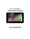
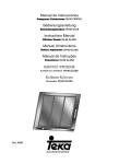
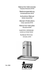
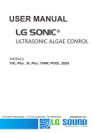
PCH BV
Kronos Security Services BV
MRS-400
User manual
Kronos Security Services B.V.
Boerhaavelaan 7
2713 AH, Zoetermeer, the Netherlands
Tel : +31 (0)79 320 07 54
Email: [email protected]
www.kronossecurityservers.nl
PCH B.V.
Darwinstraat 4
2722 PX, Zoetermeer, the Netherlands
Tel : +31 (0)79 343 23 52
Email : [email protected]
www.pchbv.nl
Page 1 of 30
Contents:
Contents:.................................................................................................................................... 2
Figures:...................................................................................................................................... 3
1 Introduction ............................................................................................................................ 4
1.1 Document Scope.......................................................................................................................................... 4
1.2 Terminology ................................................................................................................................................ 4
2. GENERAL ............................................................................................................................. 4
2.1 Introduction.................................................................................................................................................. 4
2.2 Pre-Installation............................................................................................................................................. 4
2.3 System Architecture .................................................................................................................................... 4
3. Component description.......................................................................................................... 5
3.1 MRS Unit..................................................................................................................................................... 5
3.1.1 Unit Configuration.................................................................................................................................... 6
3.2 Hardware Interfaces..................................................................................................................................... 8
3.2.1 Video......................................................................................................................................................... 8
3.2.2 GSM Antenna ........................................................................................................................................... 8
3.2.5 I/O ............................................................................................................................................................ 9
3.2.6 USB Client................................................................................................................................................ 9
3.2.7 USB Host .................................................................................................................................................. 9
3.2.6 LCD .......................................................................................................................................................... 9
3.3 MRS Server ............................................................................................................................................... 10
3.3.1 Viewing video......................................................................................................................................... 12
3.3.3 GPS Recording ....................................................................................................................................... 17
3.3.4 Audio-in.................................................................................................................................................. 18
3.3.5 Audio-out................................................................................................................................................ 18
3.3.6 Recording................................................................................................................................................ 18
3.3.6.1 Record Locally and Record on Device ............................................................................................... 19
3.3.6.2 Play local recording (video) ................................................................................................................ 20
3.3.6.3 Play local recording (audio) ................................................................................................................ 21
3.3.6.4 Play the Device Record files. .............................................................................................................. 21
3.3.7 VMD ....................................................................................................................................................... 22
3.3.8 SMS ........................................................................................................................................................ 23
3.3.9 Voice....................................................................................................................................................... 24
3.3.10 I/O ......................................................................................................................................................... 24
3.3.11 PTZ ....................................................................................................................................................... 25
3.4 Authentication............................................................................................................................................ 26
3.4.1 Users ....................................................................................................................................................... 27
3.4.2 Devices.................................................................................................................................................... 27
3.4.3 Permission level (user device access) .................................................................................................... 27
3.4.4 Default Access........................................................................................................................................ 27
3.5 Session ....................................................................................................................................................... 29
3.6 Nodes ......................................................................................................................................................... 29
3.7 IPHONE/PDA ........................................................................................................................................... 30
3.8 Web Internet Flash Client.......................................................................................................................... 30
Page 2 of 30
Figures:
Figure 1 - MRS -System Architecture..................................................................................................... 5
Figure 2 – MRS Unit ............................................................................................................................... 7
Figure 3 – MRS Monitor - Local Server setup...................................................................................... 10
Figure 4 – MRS Monitor - Client setup................................................................................................ 11
Figure 5– MRS Monitor – Enable video channel.................................................................................. 13
Figure 6 – MRS Monitor - 4 channels video window. .......................................................................... 14
Figure 7 – MRS Monitor – Channel video properties ........................................................................... 15
Figure 8 – MRS Monitor – Device location.......................................................................................... 16
Figure 9 – MRS Monitor – Video over map ......................................................................................... 17
Figure 10 – MRS Monitor – Local recording file system ..................................................................... 19
Figure 11 - MRS Monitor – enable channel for record ......................................................................... 20
Figure 12 – MRS Monitor – Play Local Recording .............................................................................. 21
Figure 13 - MRS Monitor – Play Device Recordings files ................................................................... 22
Figure 14 - MRS Monitor – VMD control On/Off................................................................................ 23
Figure 15 - MRS Monitor – VMD setup ............................................................................................... 23
Figure 16 - MRS Monitor – SMS Setup................................................................................................ 24
Figure 17 - MRS Monitor – I/O Alarm setup........................................................................................ 24
Figure 18 – MRS monitor – GPIO in/out status.................................................................................... 25
Figure 19 – MRS Monitor – PTZ Control............................................................................................. 26
Figure 20 – MRS Monitor - Authentication Server setup ..................................................................... 27
Figure 21 – MRS Monitor - Permission setup....................................................................................... 29
Figure 22 – MRS Monitor – session options......................................................................................... 29
Figure 23 – MRS Monitor - Nodes ....................................................................................................... 30
Page 3 of 30
1 Introduction
1.1 Document Scope
This document describes the operation of the MRS system.
1.2 Terminology
Term
Description
2. GENERAL
2.1 Introduction
PCH MRS System is a multimedia streaming from the field and monitoring system. It
allows streaming vido/audio/location over cellular network and monitoring everywhere on
the network. The streaming media is done using MRS units which can be located
everywhere on mobile vehicles or fix locations. Monitoring is capable on fix/mobile
control centre, mobile phones/PDA and internet web client.
2.2 Pre-Installation
The control centre server can be installed on any PC with XP and newer. Fix IP address
must be installed for the SERVER (like any web site), so the units have IP address as their
destination. If there is a firewall in the server 2 ports must be open:
12654 TCP
12655 UDP
2.3 System Architecture
The system has 2 major architectures:
1
2
M2M architecture (recommended), which based on a server with fix IP address.
Multiple units can communicate with the server as well as multiple clients.
All clients are connected to the server only.
P2P Architecture, which the server is running inside the unit. IP address of the unit
must be global and fixed to be reached from outside. This global IP must be provided
by the cellular provider.
Page 4 of 30
The system consists from the following components:
1
2
3
MRS units which can stream up to 4 channels of video, 1 audio channel and GPS
location over cellular to MRS server
MRS Server communicates with units and clients.
MRS Client communicates with server and has viewing and control capabilities of
all connected units.
Figure 1 - MRS -System Architecture
3. Component description
3.1 MRS Unit
The MRS unit is based on embedded hardware/software with built-in cellular network
interfaces.
The unit must be configured in order to work properly. The IP address of the server must
be set into the unit, parameters of the cellular provider (like APN) and options specific to
the unit.
There are two ways to configure the unit:
●
●
Input parameters are set using USB cable to a PC (recommended)
Built-In LCD and built-in function-keys.
Page 5 of 30
3.1.1 Unit Configuration
Make sure the SIM or the SD cards are not inserts.
Once the USB cable is connected to a PC with (XP or higher) new hardware is detected in
the PC asking for driver. Point to the driver attached on the CD and Install the driver.
After driver installation is completed, install the Device Config Setup application, which
allow you to configure the unit through the USB cable.
This application communicates with the unit and has a menu with the following options:
●
●
●
●
●
●
Device Identification – Let you update the device name and ID
Connection – Let you update the server IP, provider APN etc.
Recording – Let you setup the size file limit.
GPS – Let you enable/disable the GPS capability
Upgrade – Let you upgrade the unit framework.
Log – Let you log information while running.
After changing the necessary information using device config
application, the information must be burned into the unit. This is done
by using the burning key (candle light key/write to device)
After pressing this key the status down the application show:
“parameters saved”
Usually you need to change the IP address and the APN (Access Point
Name of the cellular provider) only (inside connection menu) .
Page 6 of 30
Figure 2 – MRS Unit
Page 7 of 30
3.2 Hardware Interfaces
3.2.1 Video
Video has 4 BNC connectors for input.
Make sure to connect the camera(s) to the BNC input
3.2.1 Audio
Line in and Line out
3.2.2 GSM Antenna
GSM antenna has SMA interface near the BNC.
Make sure to connect the GSM antenna to the SMA GSM connector
3.2.3 GPS Antenna
GPS antenna has SMA interface near the BNC
Make sure to connect the GPS antenna to the SMA GPS connector
3.2.4 PTZ
PTZ has 2 RS-485 output lines coming from terminal block (T+, T-), the baud rate is 2400
BPS, id=1 and PELCO D protocol
Page 8 of 30
3.2.5 I/O
There are 4 input and 4 output dry contact, In order to close the input circut you must
connect between GND line and one of the inputs. The same with the output (max 5v)
3.2.6 USB Client
USB client is used for device setup using device config application
3.2.7 USB Host
USB host is used for external modems, disk on key, USB2LAN adapter etc.
3.2.6 LCD
LCD purpose is for viewing device status, viewing video channel
Page 9 of 30
3.3 MRS Server
The MRS SERVER supports multiple units and clients. One and only one MRS SERVER
must be running in MRS system. The MRS server software is universal and can be
configured to run as part of MRS client or MRS unit. The MRS Server purpose is to
communicate with all MRS units and clients and to stream video/audio/location from units
to clients.
The MRS software is called “monitor”
The system is using 2 ports in the monitor server side:
12654- TCP
12655- UDP
These ports must be open in the monitor server side in order to let units and client to
connect to the server and stream video.
In order to let the MRS application to remember the setting as IP, open session menu and
automatic
In order to setup the MRS to act as server, open the session menu, connections and check
the local server item. Once the server is running (status bar (down the window) shows
“server is listening”, units can run and communicate with the server.
Figure 3 – MRS Monitor - Local Server setup
Page 10 of 30
In order to setup the MRS to act as client, open the session menu, connections and check
the remote server item with the server IP address. It is possible to use DNS name instead
Figure 4 – MRS Monitor - Client setup
Page 11 of 30
3.3.1 Device properties
3.3.1.1 Device control parameters
User can change and control the device from the monitor:
Device name- Rename
Restart the device
Restart the video controller
Set packet size – Default is 1000 (better not to change this parameter)
Set time of the device
Remember- this parameter can be checked in order to move the unit to the offline devices list
in case the unit is disconnected
3.3.2 Viewing video
3.3.2.1
Viewing video through device tree
Before viewing channel must be enable. In order to enable specific channel put the cursor
over the channel and right click / or use action menu then check the enable item
Page 12 of 30
Figure 5– MRS Monitor – Enable video channel
Once the MRS unit is connected, a new tree with the specified unit name appeared on the
left side of the application window. The tree expresses exactly the unit features as defined
inside the unit. Channels are viewed in the tree with their names and current bit rate and
frame rate. Indicators and output signals are viewed with their current status. If the unit has
a PTZ camera (connected to camera port 1) connected, PTZ control will be open to support
the camera.
Drag&Drop the channel to the desired window opens that channel for streaming. Double
click on open picture resize the picture to full screen; double clicking again return to the
previous setting.
Page 13 of 30
Figure 6 – MRS Monitor - 4 channels video window.
Viewing area can be split to 1, 4, 9 and 16 viewing channels.
The device name, channel name and other parameters as bit rate, frame rate can be changed
by putting the cursor on specify channel and pressing F3 or through the action menu (while
cursor on the specific channel).
Page 14 of 30
Figure 7 – MRS Monitor – Channel video properties
Right clicking on the viewing window opens small menu with the same options.
The most important parameters when viewing the video are bit rate and frame rate. The
bit rate is based on the bandwidth supported by the mobile network in the area of using,
and the bit rate of all viewing channels must be less then the bandwidth. For example, if
viewing only 1 channel and the bandwidth is 200kb then the bit rate must be less or equal
to 200kb. Frame rate can be any number from 1 to 25/30 but in low bandwidth as 200kb 10
to 15 is preferred.
3.3.2 Device location (GPS)
The MRS unit has a built-in GPS location function which transmitted to any connected
client. In order to allow GPS capability you need to check it in the configuration software
of the unit.
There are 2 options to view devices on the map
1. system level - all connected devices over specified map
2. device level - for specific device only
click on any device icon will let you open floating window for live
streaming
Page 15 of 30
Figure 8 – MRS Monitor – Device location
3.3.2.1 System level map
System level (under system tree) which you can see all devices on one map moving as
icons,. If there are more then one device icons on the map, the map is not centered.
3.3.2.2 Device level map
Device level (under specific device tree), in this case the device icon is centered
automatically every few seconds.
Page 16 of 30
Figure 9 – MRS Monitor – Video over map
3.3.3 GPS Recording
GPS route is stored on any connected monitor. The route is stored per day and
per device. You can view the route using “location view” under “view” menu
Page 17 of 30
3.3.4 Audio-in
Device level (under specific device tree), in this case the device icon is centered
automatically every few seconds.
3.3.5 Audio-out
Double clicking on the audio out channel opens the audio stream from the client to the
device. (make sure the device has speaker unit attached to line out.)
3.3.6 Recording
Recording can be done either inside the unit on a micro SD card and on each computer
which the MRS monitor server or client is running. Use action menu for both options. Use
the same option to finish recording. Viewing the recording can be done using the right
Page 18 of 30
recording layer in the tree (unit recording or client pc recording). The location in the PC
and the file size can be configured by putting the cursor on the recordings and F3 function.
(see below)
Figure 10 – MRS Monitor – Local recording file system
3.3.6.1 Record Locally and Record on Device
1
2
Select the channel that you want to record by clicking on the channel name.
Click on Action Menu and enable the record by clicking on:
"Record Locally" or "Record on Device" (you can choose both of them one by one)
If you select record on device the unit will record the channel all the time even there
is no connection with the server (bit rate of microSD is limited according to
manufacture, You can test the speed on the device using the LCD for results
Page 19 of 30
Figure 11 - MRS Monitor – enable channel for record
After you enable the record action you can see the sign beside the action, Record locally or
Record on Device. It means that the Record Locally is enabling.
Audio can be recorded as well in separate files the same way video is recorded.
Synchronize video and audio can be recorded by attaching the audio to one of the video.
Put the cursor on one of the video channels and attached the voice. The Recording video
will have synchronized audio in the file.
3.3.6.2 Play local recording (video)
To view and play records locally open the Recordings tree, the files arranged by date tree.
To play a record file choose the file by date, time, device- ID and channel name, double
clicking on the file will play it.
Page 20 of 30
Figure 12 – MRS Monitor – Play Local Recording
3.3.6.3 Play local recording (audio)
To hear play records locally open the Recordings tree, the files arranged by date tree.
Double click on audio file open audio player
3.3.6.4 Play the Device Record files.
To view the device record files, open the Recordings tree at the MRS Monitor devices tree,
the files arranged by date/time tree.
To play the record file choose the file by date, time, device- ID and channel name, double
clicking on the file will play it.
Page 21 of 30
Figure 13 - MRS Monitor – Play Device Recordings files
3.3.7 VMD
The MRS unit supports VMD which can be defined per video channel
VMD trigger is used to alarm viewing clients and sending SMS (refer to SMS section)
Page 22 of 30
Figure 14 - MRS Monitor – VMD control On/Off
VMD can be setup to beep, open the specified channel and start recording
Figure 15 - MRS Monitor – VMD setup
3.3.8 SMS
The unit can send SMS to any number of phones as a result of VMD trigger or input (i/o). Messages
can be written in any language. phone number and names must be field in the following window:
Page 23 of 30
Figure 16 - MRS Monitor – SMS Setup
3.3.9 Voice
The MRS unit can stream audio by double clicking on the microphone button in the device.
Double clicking again stops the streaming of the unit audio. The user can change the audio
parameters by clicking on the audio button and pressing F3. the user can see the audio
status at the MRS Monitor screen.
3.3.10 I/O
The MRS unit supports 4 input and 4 output signals (viewed in the tree). The signals are at
TTL level. In order to trigger input signal you need to close between input 1-4 and GND
GPIO define as trigger for the following actions:
●
●
●
●
Beep
Sending SMS to any number of phones
Start streaming on specific channel
Start recording on specific channel
Figure 17 - MRS Monitor – I/O Alarm setup
Page 24 of 30
Figure 18 – MRS monitor – GPIO in/out status
3.3.11 PTZ
The MRS system can control PTZ camera. User can control the:
Pan/Tilt/Zoom and presets according to the PTZ camera ability.
Page 25 of 30
Figure 19 – MRS Monitor – PTZ Control
The user can define a set of presets by adjusting the camera to the object and save it by
name. To apply the preset choose the preset name from the list box "move to", then the
camera will focused to the choosing object. The duration scale is to simulate the time of
one click. By moving the duration up/down will long/short the PTZ duration command
accordingly.
The MRS supports channel 1 camera with PELCO D protocol.
3.4 Authentication
In general each device and user can be defined with password for authentication in the
server.
Permission is defined by the server software only (permission icon) for users, devices and
the connection between users and devices.
Page 26 of 30
Figure 20 – MRS Monitor - Authentication Server setup
3.4.1 Users
Each user can be defined in the server with password (the password is for authentication
only)
3.4.2 Devices
Each device can be defined in the server with password (the password is for
authentication only)
3.4.3 Permission level (user device access)
Each user can be defined with permission access for specific device:
Forbidden- no access
Aware- view connection only
Passive- View video without capability of change (bit rate/Frame rate)
Active – View and change bit rate / Frame rate
Admin- Control any parameter
3.4.4 Default Access
Page 27 of 30
The “default device access” screen defines the access level of each device which is not
specified in “user device access”.
The “default access” screen defines the user access level of all other devices (not
specified devices either in “user device access” or “default device access”)
Unlisted devices (not in the devices list) can be allowed or not allowed in the system.
Unlisted users (not in the users list) can be allowed or not allowed in the system.
Page 28 of 30
Figure 21 – MRS Monitor - Permission setup
3.5 Session
Session is set of parameters which defines the current definition of the MRS monitor
application. Session includes open channels and channel parameters. Session can be saved
to a file and reload anytime.
User can enable the “automatic” button which will save the current setting in the last
session when exiting the program. After restarting, the program will load last updated
session which was saved automatically when exit.
Figure 22 – MRS Monitor – session options
3.6 Nodes
The user can view all connected devices and clients using the Nodes list.
Page 29 of 30
Figure 23 – MRS Monitor - Nodes
3.7 IPHONE/PDA
MRS support Iphone client for live video monitoring. Download iMRS app from apple
appstore
3.8 Web Internet Flash Client
The monitor server support flash client in any web browser by using server IP address as follows”
http://”server ip address”:12654/videostreams.html
If video and voice is needed (synchronized) you need to attached the voice to one of the video channel
Put the cursor on the video channel and right click on the mouse for attached audio channel.
Page 30 of 30