1
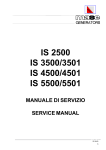
User manual RAD pneumatic
torque wrenches
- INNOVATION DRIVEN PERFORMANCE
USER MANUAL
PNEUMATIC SERIES
35 - 11.500 Nm
Version 2.0 - march 2015
1
User manual RAD pneumatic
torque wrenches
Table Of Contents
1. General instructions 2.Assembly
3. Air pressure regulator
3
4. Setting torque
5. Movement of the reaction arm
5
6.Safety
7. ATEX certification
8.Warranty
6
9.Contact
8
Version 2.0 - march 2015
2
3.1 ½” NPT inlet
3.2 ½” NPT outlet
3.3 Automatic oiler
5.1 Installing the reaction arm
5.2 Reactie arm height
5.3 Reaction arm foot
5.4 Reaction point
8.1 New tool warranty
8.2 Repaired tool warranty
3
4
4
4
4
5
5
6
6
6
7
8
8
8
User manual RAD pneumatic
torque wrenches
1. General instructions
NOTE: Do not operate the tool before reading these instructions. If breakdown, malfunction or damage
occurs, do not attempt to repair, please contact RAD Torque Systems B.V. immediately. When working in
an explosive environment; Always make sure you use an ATEX certified torque wrench. This is indicated
by the Ex marks on the torque wrench and FRL unit and the green earth cable with clamp on the FRL
unit.
RAD pneumatic torque wrenches are reversible, non-impacting, torque controlled tightening tools and
must always be operated with the following:
• Clean dry air supply (air consumption can be found on page 4)
• Cage assembly with lubricator and regulator
• Impact sockets with locking pin and o-ring
• Proper reaction arm with retaining ring
These torque wrenches contain metal components which can be dangerous if the torque wrench and FRL
unit are not ATEX proof.
2. Assembly
1. Blow out hoses before connecting
1a. When ATEX certified; make sure that the original RAD hose is used between the torque wrench and
the FRL unit
1b. When ATEX certified; first connect the clamp of the earth cable (green color mounted to the FRL unit)
to the workpiece
1c. When used in areas with dust explosion risks, install the silencer to the air outlet of the torque wrench
to limit dust whirling. Preferably, clear the environment of dust within a radius of 1 meter around the
workplace before operating
2. Connect the wrench air inlet to the outlet side of the Cage Assembly, observing airflow direction
3. Connect air supply to inlet side of the Cage Assembly using a minimum hose size of 1/2” (1.27cm)
4. Check oil level in lubricator and fill to correct level
5. Fasten and secure the reaction arm on the jagged side of the gearbox with the retaining ring
6. When ATEX certified; after placing the socket, secure the socket with a pin and o-ring lock to prevent
loosening of the socket.
Regulator cage setup
Air pressure regulator
To increase air pressure (and torque),
turn the “T” handle clockwise.
Note: the tool must always be running
when setting air pressure.
RAD tool storage
½″ NPT outlet
Install the supplied airline to
the 1/2” NPT outlet port on
the automatic oiler. The quick
connect fitting at the opposite
end of the hose will be attached
to the RAD® tool.
½″ NPT inlet
Install your air supply to the 1/2”
NPT female port in the regulator. A
minimum 1/2” airline must be used
capable of 100psi at 30 cfm.
Liquid filled pressure
gauge
Torque chart
Always set air pressure with tool running
Earth cable and clamp
Only with ATEX certified version
Air filter
Version 2.0 - march 2015
Automatic oiler
Fill the automatic oiler with air tool
oil only. Fill from the top, or by
removing and filling the bowl, then
reinstalling from the bottom.
3
User manual RAD pneumatic
torque wrenches
WARNING! Always check all air hose connections before the air supply is activated.
When the tool is in operation the reaction arm rotates in the opposite direction to the output square drive
and must be allowed to rest squarely against a solid object or surface adjacent to the bolt to be tightened.
WARNING! Always keep hands clear of the reaction arm when the tool is in use or serious injury could
result.
3. Air pressure regulator
Rotate clockwise to increase the air supply, and counter-clockwise to decrease the air supply. Note: the
torque wrench should run freely while setting the torque. The direction is not important.
3.1½” NPT inlet
Connect your air supply to the ½“ NPT inlet. The diameter of the hose should be at least ½ “.
3.2½” NPT outlet
Connect the supplied air hose to the ½“ NPT outlet automatic oiler. The outlet on the other end of the hose
is attached to the torque wrench.
NOTE: The water tank from the filter outlet should be emptied periodically. The drain filter is accessible
from the bottom of the FRL unit.
3.3Automatic oiler
Fill the oiler with oil only for air tools.
NOTE: Ensure a sufficient compressor capacity in terms of volume and pressure.
Air motor
Torque wrench
NPW 120
100SL
Air consumption
275SL
275SL (-2)
750SL (-2)
792 Liter at 6,7 bar per minute
10GX (-R)
14GX (-2)/(NX)
20DX (-2)
NPW 180
1100NG (-2) (-XR)
1900NG (-2) (-XR)
1130 Liter at 6,7 bar per minute
34GX
NWP 200
4000 (-2)
46GX
1727 Liter at 6,7 bar per minute
6800
UXR
Version 2.0 - march 2015
80DX, 115GX, 110DX
900 Liter at 6,7 bar per minute
4
User manual RAD pneumatic
torque wrenches
4. Setting torque
Every RAD torque wrench is supplied with a torque chart which relates torque output to air pressure.
Set the torque as follows:
1. Ensure the Forward/Reverse is set to “Forward”
2. Establish the air pressure required using the torque chart provided with the tool
3. Adjust the regulator until the correct pressure is shown on the gauge
4. The wrench must be free running while adjusting the air pressure to give the correct setting.
WARNING: Exceeding the maximum air pressure will overload the wrench and may cause serious
damage. When removing a bolt from the the connecting, the direction switch must be set on “reverse”.
Then, the maximum torque need to be chosen.
Operating the torque wrench:
1. Fit the wrench with the correct size impact socket to suit the bolt to be tightened.
2. Check that the Forward/Reverse switch is set correctly.
3. Rotate the handle to a convenient position relative to the reaction arm.
4. Fit the tool onto the bolt to be tightened with the reaction arm adjacent to the reaction point.
5. Squeeze the trigger partially to bring the reaction arm into contact with the reaction point.
6. Fully depress Trigger and keep fully depressed until wrench stalls. If the Trigger is released before the
wrench stalls, full torque will not be applied to the bolt.
7. Release Trigger and remove the tool from bolt.
5. Movement of the reaction arm
5.1Installing the reaction arm
Ensure the reaction arm and retaining ring are installed securely to hold the reaction arm in place. Make
sure the reaction arm is in contact with a solid reaction point before you operate the tool. When the tool
is in operation the reaction arm rotates in the opposite direction to the output square drive and must be
allowed to rest squarely against a solid object or surface adjacent to the bolt to be tightened (Figure 1).
Reaction point
Clockwise
operation
Counter clockwise
operation
Figure 1
WARNING: In use, this tool must be supported at all times in order to prevent unexpected release in the
event of a fastener or component failure!
Version 2.0 - march 2015
5
User manual RAD pneumatic
torque wrenches
5.2Reactie arm height
Ensure the height of the socket is even with the height of the reaction arm as seen below in Figure 2A.
The height of the socket cannot be shorter or higher than the height of the reaction arm as seen below in
Figure 2B and 2C.
✔
Figure 2A
✘
Figure 2B
✘
Figure 2C
NOTE: Improper reaction will void warranty and can cause premature tool failure.
5.3Reaction arm foot
Ensure the foot of the reaction arm aligns with the length of the nut as seen in Figure 3A. The length of the
foot cannot be shorter or longer than the nut as seen in Figure 3B and 3C.
Figure 3A
✔
Figure 3B
✘
Figure 3C
✘
5.4Reaction point
Ensure the reaction arm reacts off the middle of the foot as seen in Figure 4A. Do not react off the heel of
the reaction foot as seen in Figure 4B.
Please contact RAD Torque Systems B.V. or your local RAD authorized distributor for custom reaction
arms.
WARNING: Always keep your hand and body parts clear of the reaction arm and barrel when the tool is
in operation (Figure 4C).
Figure 4A
✔
Figure 4B
✘
Figure 4C
✘
6. Safety
RAD tools use pressurized air to develop very large forces to tighten and loosen threaded fasteners. For
your safety and that of others, warning labels and attention labels are prominently attached to the carrying
cages, reaction accessories, and tools.
NOTE: Make sure you observe the directions on the warning labels at all times.
Version 2.0 - march 2015
6
User manual RAD pneumatic
torque wrenches
RAD tools have been designed with safety in mind however, as with all tools you must observe all general
workshop safety practices, and specifically the following:
• Before using your new tool, get familiar with all its accessories and how they work
• Always wear safety goggles when the tool is in operation
• When working in an explosive environment, always be sure you use an ATEX certified torque wrench
• Make sure the reaction arm is in contact with a solid contact point before you operate the tool
• Keep your body parts clear of the reaction arm and the contact point
• Set your air pressure while the tool is running
• Refer to the enclosed torque chart to set the correct air pressure regulator setting for a required torque
• Never exceed the maximum air pressure shown on the torque chart
• Always use the regulator and oiler that is supplied. Failure to do this voids the warranty and can place
you in danger
• Be sure to use a minimum 1/2” airline to the cage assembly as this will allow for adequate air flow
• Make sure the reaction arm snap ring is securely in place to hold the reaction arm or blank in place.
RAD tools are safe and reliable. Not following precautions and instructions outlined here can result in
injury to you and your fellow workers. New world technologies incorporated is not responsible for any such
injury.
7. ATEX certification
As option, RAD torque wrenches are available with ATEX certification. The applied RAD ATEX certification
is explained below. See our website for more information: www.radtorque.nl/atex.
The RAD torque wrenches are marked according to ATEX 95 and suiteable for use in zone 1, 2, 21 and 22
with explosion group IIA and IIB or dust group IIIA and IIIB.
II = Suitable for explosive environment
above ground
Ex = certified by an approved
CENELEC test center
2G/D = Protection class 2 for gas and dust,
therefore suitable for zones 1, 2, 21 and 22
CE = Complies relevant
EC directives
T6 = Maximum surface temperature <85°C,
therefore suitable for zones with
temperature classes T1 till T6
CE
II 2G/D Ex c IIB/IIIB T6
Ex c = meets the constructional safety
according to EN 13463-5
IIB = Explosion group, therefore
suitable for gas zones with explosion
group IIA and IIB
IIIB = dust group, therefore
suitable for dust zones
with dust group IIIA and IIIB
Registration number: LCIE 8663323.01.15
If you have an ATEX certified torque wrench please note the following:
• Socket must at all times be secured using the locking pin and o-ring
• The reaction arm must be at all times be secured using the retaining ring
• There should be at all times a earth connection with the work piece.
Version 2.0 - march 2015
7
User manual RAD pneumatic
torque wrenches
8. Warranty
8.1New tool warranty
Any new tool branded with the RAD name and purchased from RAD Torque Systems B.V., or through one
of its authorized distributors or agents, is warranted to the original purchaser against defects in materials
and workmanship for a period of twelve (12) month from the date of delivery to the end user. This
guarantee is valid until fifteen (15) months after the original calibration date.
Furthermore, the warranty conditions determine that no warranty applies if:
1. The defect, wholly or partly, is due to unusual, inappropriate, improper or careless use of the product;
2. The defect, wholly or partly, is due to unusual, is due to normal wear and tear or lack of proper
maintenance;
3. The defect, wholly or partly, is due to unusual, is due to installation, assembly, modification and / or
repair by the customer or by third parties;
4. The product altered, modified, used or processed is;
5. The product is transferred to a third party;
6. RAD Torque Systems B.V. has abtained the product, wholly or partly, from a third party, and RAD
Torque Systems B.V. can not claim compensation under warranty;
7. RAD Torque Systems B.V. in manufacturing of the product raw materials, and suchlike has used on
the instructions of the customer;
8. The product has a small deviation in it’s quality, finishing, size, composition and suchlike, which is not
unusual in the industry or if the defect was technically unavoidable;
9. The customer has not fulfilled all obligations under the agreement promptly and correctly towards RAD
Torque Systems B.V..
8.2Repaired tool warranty
After the warranty has expired a three (3) month warranty applies to the original purchaser against
defective in material or workmanship or both from the date of repair.
To qualify for the above mentioned warranties, written notice to RAD Torque Systems B.V. must be given
immediately upon discovery of such defect, at which time RAD Torque Systems. will issue an authorization
to return the tool. Freight costs must be paid in advance. When returning a tool, the reaction arm/s being
used with the tool must also be returned.
For the latest warranty terms, please see our sales conditions on our website www.radtorque.nl
9. Contact
RAD Torque Systems B.V.
Zuidergracht 19
3763 LS Soest
Telephone: 035-5882450
E-mail: [email protected]
Website: www.radtorque.nl
Version 2.0 - march 2015
8
User manual RAD pneumatic
torque wrenches
MINING
OIL & GAS
WINDPOWER
AEROSPACE
PETROCHEMICAL
MANUFACTURING
COMMERCIAL VEHICLE INDUSTRY
MASTER DISTRIBUTOR FOR EUROPE, MIDDLE EAST
AND NORTH AFRICA:
RAD TORQUE SYSTEMS B.V.
ZUIDERGRACHT 19
3763 LS SOEST
THE NETHERLANDS
PHONE.: +31 (0)35 - 5882450
E-MAIL:[email protected]
[email protected]
[email protected]
WWW.RADTORQUE.NL
Version 2.0 - march 2015
9