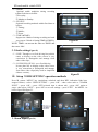
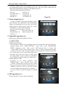
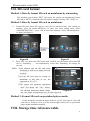
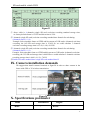
1
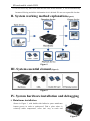
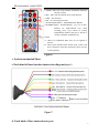
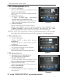
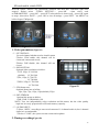
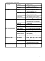
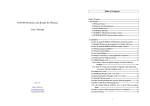
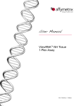
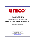
SD CARD
MOBILE VEHICLE DVR
INSTALLATION
MANUAL
Installation manual applies to the following mode DVR-E
please read carefully before operating
INDEX
SD card mobile vehicle DVR
I. Installation specification and rules
II. System working method explanation
III. System essential element
IV. System hardware installation and debugging
i. Mainframe installation
ii. Camera installation
iii. Microphone installation
iv. IR remote control graphical diagram
v. System connected lines
V. System software operation installation
i. System setting
ii. Video setting
iii. User setting
VI. SD card operation installation
VII. SD card format
VIII. Storage time reference table
IX. Camera installation demands
X. Specifications parameter
I. Installation specification and rules
i. Installation safety specification
1. The installation of wiring should be carry out by skilled and experienced worker in order
to ensure the safety of machine is installed.
2
SD card mobile vehicle DVR
2. The machine can be installed between voltage 12 V - 36V of vehicle.
3. The drill can not touch, damage, airway obstruction and wires when wiring, so as not to
cause an accident.
4. When all the wires are connected , must use strapping tape to bind the bare copper wire
avoid to cause short circuit with each wire and shatter by some sharp of vehicle parts
cause accident.
5. Installation of camera, find a place where passengers are not easy touch, then put the
camera’s lines in and adjustable camera’s angle to the right point of viewing, then fixed
it with attached seals. The camera infrared light can not more than1 2 lights.
6. Do not install the microphone in the wind, because the microphone is higher sensitivity.
8. This system connected lines as following: First all, connected all the accessories signal
lines, examples of cameras and microphone, then connected power wire and use
strapping tape to bind well. Finally, use 4 screws fix plug to mainframe.
ii. Operation safety rules
1. This machine output power is DC 12V, not allowed connect any other external supply
power except ex-factory configures.
2. Only support format SD card directly on mainframe and specialized player media directly,
or else will cause the machine can not record.
3. Not allowed take the machine apart illegally except have got manufacturer permission, or
else we can not supply free warranty for you.
4. Keep away water and any liquid away from machine in order not to cause short circuit.
5. Keep away any heavy goods press on mainframe, in order to avoid excessive hot to shatter
machine.
6. Please handle with care in transit as electronic products.
7. Use key open lock, the machine will stop record and video clip characters are shown blue,
wait the REC light stop flicker for a moment ,then draw out SD card slowly in order not to
shatter SD card or cause video clips loss.
8. Please format SD card on mainframe or specialized player media after viewing video clips
every time or within a week(refer to SD card format).
9. Keep SD card defender unlocked, then insert it to the card jack slowly until back lock
after power off in order not to shatter machine.
3
SD card mobile vehicle DVR
10. Do not insert any other non dedicated SD card in this machine ,it will be automatically
formatted if doing and all the information in it is deleted. We are not responsible for that.
II. System working method explanation(Figure1)
Figure1
III. System essential element(Figure2)
Figure2
IV. System hardware installation and debugging
i. Mainframe installation
Shown in Figure 3, with double-sided adhesive paste mainframe
bottom groove in order to quakeproof. Find a place where is
relatively stable temperature, water isn’t easy to reach and
4
Figure3
SD card mobile vehicle DVR
ventilation in vehicle, use 4 screws fixed mainframe, and bind all machine lines well with
strapping tape.
ii. Camera installation
Support 4 channels video-in, the mainframe can independently supply power for
camera(DC12V), Shown in Figure 4, as possible as all the
camera signal lines should wiring in the interior of vehicle, do
not expose or visible them outside. Don’t vigorously pull the
lines when wiring to prevent pull off them , and also be careful
don’t damage lines to prevent short-circuit when twisted the
screws. Then adjustable camera’s angle to the right of viewing.
With drill making more than 3 screw holes and using screws to
Figure4
fix bottom of the camera.
iii. Microphone installation(Figure5)
Support 4 channels audio-in, the mainframe can independently supply power for
microphone(DC12V).But
1
channel
audio
is
recommended
for
users.
Figure5
iv. IR remote control graphical diagram(Figure6)
5
SD card mobile vehicle DVR
1. MENU: Enter into setup function (mainframe unlocked
and stop record);
2.SET:Enter into all submenu items setup function;
3.EXIT:Exit all items ;
4.OK:Save all settings function;
5. NAVIGATION KEYS:UP,DOWN,LEFT, RIGHT
6.NUMBER KEYS:Numbers&letters, 1,2,3,4,5 of these
numbers are multi-function keys when
recording, press 1,2,3,4 shown as viewing
independently channel and press 5 shown as
viewing 4 channels simultaneously;
NOTE:
A. Other keys (SWITCH, DEL, EN) are not applied at
present.
B. This system with IR remote control setup, so there will
have a moment to enter into main menu, please wait for
a while patiently…
Figure6
v. System connected lines
i. Each kind of lines function instruction diagram(Figure7)
Figure7
ii. Each kind of lines instruction(Figure8)
6
SD card mobile vehicle DVR
Figure8
iii. Total combined lines function instruction(Figure9)
Figure9
V. System software operation installation
i. Setup ‘SYSTEM SETTING’ operation methods
Press IR remote ‘MENU’ key (mainframe unlocked and then REC indication light have
stopped flicker)---select ‘SYSTIME SETTING’--- press‘OK’ —then select such as
‘DATE&TIME’ ---press‘OK’ ---press‘SET’(selected item is shown red) ---press‘OK’ again
7
SD card mobile vehicle DVR
to setup---then select ‘SAVE’--- press ‘OK’ to save all settings ---press‘EXIT’ the MENU.
As bellow figure10&figure11.
Figure10
1. Date&time
0 (Figure12)
Figure11
0
(1)DATE SETTING: Set the system date(M/D/Y);
(2)TIME SETTING: Set the system time(H/Min/Sec);
Optional time stamp as bellow:
① RTC time (recommend)
② Network time (network selected)
③ GPS time (GPS selected)
(4)DELAY RECORDING:
Set the system continuous record times after no ignite
power input;
Figure12
(5)EXIT MENU TIME:
The system will automatically return video interface after fixed time out when set this
0
item;
(6)WEEK SETTING:
This item is not enable at present, but it will be default changed with “DATE SETTING”
synchro.
NOTE:
Must
OK
to.e.
nable
.
....
..
.
.
.press
.
.
.
.
..
..
.
.
.
.
.all
.
.
.settings
.
.
.
.
.
..
..
2. Basic setting(Figure13)
(1)VIDEO OUTPUT STANDARD:
PAL and NTSC(optional);
(2)VIDEO PACKING TIME:
Set every video clip packing time, the shortest time is
5min and the longest time is 60min;
(3)LANGUAGE SETTING:
Simplified chinese and English(optional);
Figure13
(4)ADJUSTABLE INFO DISPLAY:
①select ‘OPEN’: Display Date, Time, Brake, Speed and license plate NO. stamp on
0
video screen.
②Select ‘CLOSE’: Hide Date, Time, Brake, Speed and license plate NO. stamp on
video screen.
8
SD card mobile vehicle DVR
3. SD card management(Figure14)
(1)CYCLIC COVERAGE:
①Select ‘YES’:DVR keeps recording by covering
when SD card is full(default);
②Select ‘NO’:DVR will stop recording when SD
card is full;
(2)MEMORY METHOD:
① Select ‘S-CARD’-single card-card1,all
the video clips will just storage in card1;
②Select ’D-CARD’-double card-card1&card2,
all the video clips will storage in both of cards;
Figure14
(3)FORMAT MEMORY:
Directly format SD card on machine as bellow;
0
Press IR remote ‘SET key to enter into submenu as figure14, press UP,DOWN to select
“FORMAT MEMORY”, then press OK to confirm. The system will give remind
whether format SD card memory at this time ,then press OK to confirm again;
SPECIAL
NOTE:
The
selected
item
is..
shown
red
and
format
mem
is..
with
immediate
........
...
..
.
..
.
.
.
.
.
.
..
.
...
.....
.
..
...
.
...
..
..ory
.
.
..
.
.
..
...
.
.
.
.
.
effect,
the
files
in.SD
card
memory
lose
.
.
.
.
.
.
.
.all
.
.
..
.
..
.
.
.
.which
..
.
.
.have
.
.
.
.been
.
.
.
.saved
.
.
.
.
..
...
.
.
..
...
.
.will
..
.
.permanently
.
.
...
.
.
.
.
.
..
.
.
.
.
4. Password(Figure15)
(1)VALID PASSWORD:
①Select ‘VALID’ is shown enable password
management;
②Select ‘INVALID’ is shown disable password
management;
(2)PASSWORD MANAGEMENT:
Set a password to manage this DVR system;
(3)PASSWORD CONFIRM:
Enter password again as consistent with above.
5. EX-factory(Figure16)
(1)RESTORE EX-FACTORY DEFAULT:
Set all settings restore original data;
(2)IMPORT PARAMETERS:
Use SD card import relevant parameters which
have set in advance in order to rapid debugging;
(3)EXPORT PARAMETERS:
Export relevant parameters to SD card memory in
order to rapid debugging;
(4)SYSTEM UPGRAGE:
Just for manufacturer software upgrading, user
can not operate.
Figure15
0
Figure16
ii. Setup ‘VIDEO SETTING’ operation methods
0
9
SD card mobile vehicle DVR
Press IR remote ‘MENU’ key (mainframe unlocked and then REC indication light have
stopped flicker)---select ‘VIDEO SETTING’--- press‘OK’ —then select such
as‘PARAMETERS’ ---press‘OK’ ---press‘SET’(selected item is shown red) ---press‘OK’ again
to setup---then select ‘SAVE’--- press ‘OK’ to save all settings ---press‘EXIT’ the MENU. As
bellow fugure17&figure18:
Figure17
Figure18
1. Video parameters(Figure19)
0
0
(1)SET INSTALL:
Set each channel whether need to install camera
①Select ‘ENA’-enable, this channel will be
connected camera and record;
②Select ‘DIS’-disable, this channel will not
record.
(2)RESOLUTION:
Optional video resolution as bellow:
①CIF, 15fps, P: 356*288
(default)
N: 356*240
②D1, 12fps, P: 720*576
N: 720*480
③HD1, 25fps, P: 720*288
N: 720*240
Figure19
(3)FPS(frame rate):
Optional frame rate as bellow:
0
2fps, 5fps, 7fps, 12fps, 15fps(default), 25fps.
(4)BIT-STREAM:
Optional bit-stream as bellow:
128K, 256K, 512K(default), 1M.
NOTE: User can independently select resolution and bit-stream, but the video quality
high-low inversely proportional to SD card memory capacity.
(5)AUDIO INPUT:
①Select ‘OPEN’, according to users need connected 1~4 channel audio-in, but 1 channel
audio-in is recommended;
②Select ‘CLOSE’, the system can not connect microphone.
2. Timing recording(Figure20)
10
SD card mobile vehicle DVR
(1)WEEK:
Optional enable multiplex timing recording
within fixed time as bellow:
①Everyday;
② Monday to Sunday.
(2)STATUS:
Optional recording methods within fixed time as
bellow:
①Timing;
②Mobile;
③Event.
(3)TIME1&TIME2:
Support set 4 kinds of timing recording and each
way can set 2 kinds of timing(TIME1&TIME2);
NOTE:
TIME1
can
not
the
same
as..
TIME2
and
....
..
.....
.
..
.
.set
.
.
..
.
..
....
.....
..
Figure20
also
‘24h’.
.
.
.
.cross
.
.
.
.
..
...
.
.
0
3. Vehicle setting(Figure21)
(1)LINE: Through set a fixed driving line(vehicle
route) to display on the video screen is very
convenient to distinguish and manage from
other video clips;
(2)LICENSE PLATE NO.: set a fixed driving
license plate NO. to display on the video screen
is very convenient to distinguish and manage
from other video clips(Only used in simplified
chinese version);
iii. Setup ‘USER SETTING’ operation methods
Figure21
0
Press IR remote ‘MENU’ key (mainframe unlocked and then REC indication
light have
stopped flicker)---select ‘USER SETTING’--- press ‘OK’ —then select such as ‘ALARM
INPUT’ ---press ‘OK’ ---press ‘SET’(selected item is shown red) ---press ‘OK’ again to
setup---then select ‘SAVE’--- press ‘OK’ to save all settings ---press ‘EXIT’ the MENU. As
bellow figure22&figure23:
1. AlarmFigure22
input(figure24)
0
Figure23
0
11
SD card mobile vehicle DVR
Set these 3 kinds of alarm input methods to meet user different demands. The mainframe
will automatically display corresponding letter on the video screen after setting when the
alarm input signal line have triggered ‘LEV-HIGH’ power-in.
Optional corresponding letter as bellow:
Door--M
Coin box--Q
In vehicle alarm--A
Turn left--R
Turn right--L
Loudspeaker--B
Big light--D
Air condition--K
Figure24
2. Alarm output(figure25)
0
Set these 2 kinds of alarm output methods to meet
user demands. The mainframe will automatically
display corresponding letter on the video screen after
setting and the alarm output signal line output
‘LEV-HIGH’ or ‘LEV-LOW’ power(set);
Optional corresponding letter as bellow:
Speeding--S
Door is not closed--D
Emergent brake--B
Motion detection--M
Video lost--C
3. Adjustable speed(figure26)
Figure25
Optional speed calibration methods as bellow:
0
(1) 100M-CALIB;
(2) KM/H-CALIB.
①Details 100M-CALIB:
Press IR remote ‘MENU’ key (mainframe unlocked and then REC indication light have
stopped flicker)---select ‘USER SETTING’--- press ‘OK’---select ‘ADJUSTABLE
SPEED’ submenu------press ‘OK’ ---press ‘SET’(selected item is shown red)
---select‘100M-CALIB’—press ‘RIGHT’ key to select ‘CALIB-’ button(selected button
is shown red)---press ‘OK. The pulse number is ‘0’(selected title is shown purple),then
the vehicle kept an even speed 100m and stop at
this point. Press ‘OK’ key to select ‘CALIB-’ again,
the pulse number can be counted by automating.
Press ‘EXIT’ key and all settings are enabled now.
②Details KM/H-CALIB:
According to the above operation select
‘KM/H-CALIB’ ’—press ‘RIGHT’ key to select
‘CALIB-’ (selected title is shown red). The vehicle
keep an even speed when the driving speed up to
‘40KM/H’ ,then press ‘OK’ key, the pulse number
can be counted by automating after countdown 3
Figure26
sec. Press ‘EXIT’ key and all settings are enabled
now .
0
4. GPS speed(Figure27)
The main function is set the vehicle speed limit
12
SD card mobile vehicle DVR
(1) SPEED SOURCE:
Optional speed source as bellow:
①Select‘VEHICLE’.Via speed amplifier connected mainframe speed line with the
vehicle actual speed in order to capture speed to display on video screen;
②Select ‘GPS’. Via mainframe GPS speed to capture vehicle speed to display on video
screen (mainframe must have built-in GPS module).
(2) MAX SPEED:
Set the max driving speed function;
Figure27
The system will sound alarms when the driving speed crossed this max speed(sound
alarms method have set in ‘ALARM OUTPUT’ item).
0
(3) ALLOW SPEEDING TIME:
Set allowed speeding time function;
The system will sound alarms when the driving speed crossed max speed and this
limited time(sound alarms method have set in ‘ALARM OUTPUT’ item).
VI. SD card operation installation
1. Pull out SD card
As following figure 28,use key to clockwise open this lock, the
machine will stop record and video clip characters are shown blue,
wait the REC indication light stop flicker for a
moment(sometimes ,the REC indication light on or off is normal).
Pushed SD card panel on left, then slowly press SD card and move
hand off, it will be pop-up automatically, then pull out.
NOTE:
front
nel
-marked
which
is.
.....①
.The
..
.m
.ainframe
.
.
.
.
.
....
.
..
.pa
.
.
.
.
.have
.
.
.
.well
..
.
.
.
..
.
.
.
..
.
.
.
..
Figure28
card1
ard2.
indication
light
flick
er
then
.
.
.
..and
.
..c.
.
.
..
.The
..
.REC
....
.
.
.
.
.
.
.
...
.
..
.will
..
.
.not
..
..
.
.
.
.
.
..
.
.
.pull
..
.
.out
..
.SD
..
0
card;
.
.
.
.
.
②
card
when
the
REC
indication
light
is..
flicker
ing
in.order
.Not
..
.allowed
.
.
.
...
.pull
..
.
.out
..
.SD
...
.
.
..
.
.
..
.
..
...
..
.
.
.
.
.
...
.
..
..
.
.
.
.
.
.
.
...
.
.
.
.
.not
..
.
to
shatter
card.
.
..
.
.
.
.
.
..
.
.
.
.
2. Insert SD card
Insert SD card to jack and press it slowly in unlocked state, close
SD card panel on right, then close lock with key as figure29(press
key slowly). The machine will turn on and record at this time ,
video clip characters are shown red, REC indication light is
flickering.
NOTE:
to..
mainframe
front
marked
which
is.
.....①
.According
..
.
.
.
.
.
.
..
.
.
.
.
.
....
.
..
.panel
.
.
.
.
.have
.
.
.
..
.
.
.
.
..
.
.
.
..
card1
ard2.The
indication
light
flicker
.
.
.
..and
.
..c.
.
.
..
.
..
.REC
....
..
.
.
.
.
.
...
.
..
.will
..
.
.not
..
..
.
.
.
.
.
.
t.
hen
pull
out
SD
card;
.
.
...
.
...
....
.
.
.
.
Figure29
②
card
when
the
REC
indication
light
is..
flickering
in.
.Not
..
.allowed
.
.
.
...
.pull
..
.
.out
..
.SD
...
.
.
..
.
.
..
.
..
...
..
.
.
.
.
.
...
.
..
..
.
.
.
.
.
.
.
...
0
order
to.shatter
;
.
.
.
.
.not
..
..
.
.
.
.
.
.
.card
.
.
.
.
.
③
the
card
is.completely
in.order
to.vandal
.Please
.
.
.
.
.
.sure
.
.
.
..
.
.SD
...
.
.
.panel
.
.
.
.
..
.
...
.
.
.
.
.
.closed
.
.
.
.
.
..
.
.
.
.
..
.
.
..
.
.proof
.
.
..
.
machine
normal
working.
..
.
.
.
.
...
...
...
.
.
.
.
.
.
13
SD card mobile vehicle DVR
VII. SD card format
Method 1: Directly format SD card on mainframe by automating
This machine system adopt ‘EXT2’ file layout, the system can automatically format
SD card as ‘EXT2’ if insert the other file layout, example of using ‘FAT, 32FAT’ etc.
Method 2: Directly format SD card on mainframe
(1) Format SD card: Insert SD card to card1 jack in unlocked state, after turning on
machine, press IR remote‘MENU’key to enter into main setting menu---select
‘SYSTIME SETTING’--- press ‘OK’ to enter into submenu—select ‘SD management’.
As figure30 &figure31:
Figure30
Figure31
(2) Press ‘SET’ key, then select‘OK’ button with ‘DOWN’ key, the system will remind SD
0
card 0is ‘formatting……’ and automatically restart after formatting,
all settings are
succeed.
NOTE:
allowed
out
SD
....
.①
.Not
..
..
.
.
...
. pull
..
.
..
.
..
. card
.
.
.
. when
..
.
.
formatting
in.order
to.shatter
card
.
.
...
.
.
.
.
..
.
.
.
.
.not
..
..
.
.
.
.
.
.
.SD
...
.
.
.
seriously.
.
.
.
.
..
.
.
.
.
②
the
be..
format
on.
.All
..
..
.
. SD
.. card
.
.
.
. must
..
.
..
.
...
..
mainframe
first
time
to. use,
..
.
.
.
.
... at
.
..
.
.
.
..
... .
.
.
.
. not
..
.
supported
or.TV.
.
....
.
.
.
.on
..PC
...
..
.
③
system
automati
c. attachment
.T
.he
.
..
.
.
.
.. will
..
.
..
.
.
...
.
.
.
.
.
.
.
...
.
.
name
‘lost+found’
‘vdvr’
folders,
.
....
.
.
.
.
.
.
....
.and
.
...
...
.
..
.
.
.
.
.
.
.
Not
allowed
delete
‘lost+found’
folder
,
..
..
.
.
...
..
.
.
.
.
.
.
.
.
.
.
.
.
....
..
.
.
.
.
.
.
and
‘vdvr’
folder
in..
it.
.
...
...
.
.
.
.
.
.
.
.will
..
.
.automatic
.
.
.
...
.
.
.save
.
.
.
.all
.
.
.video
.
.
.
.
.clips
.
.
.
.
..
.
.
Figure32
0
Method 3: Format SD card on specialized player media
Firstly install this specialized player media in you PC, then open it, select SD
card item to format or clear up in the bottom-right corner.(refer to specialized
player media installation manual).
VIII. Storage time reference table
14
SD card mobile vehicle DVR
Figure33
① Above table is 4 channels (single SD
0 card) real-time recording standard storage time,
ex-factory default frame is 15 FPS and bit-stream is 512k.
②3 channels (single SD card) real-time recording standard time formula for calculating:
4 channels time*(1+1/4)
Example: Select machine frame at 15FPS and bit-stream at 512K under 4 channels real-time
recording, the 16G SD card storage time is 23.4H. So we could calculate 3 channels
real-time recording storage time is 23.4*(1+1/4)=29.25H.
③2 channels (single SD card) real-time recording standard time formula for calculating:
4 channels time*(1+1/2)
Example: Select machine frame at 15FPS and bit-stream at 512K under 4 channels real-time
recording, the 32G SD card storage time is 46.8H.So we could calculate 2 channels real-time
recording storage time is 46.8*(1+1/2)= 70.2H.
④Double SD cards standard time=single SD card standard time*2
IX. Camera installation demands
We suggest that install cameras locations as figure34 in order to share camera in the
future with GPS or 3G wireless transmission.
Figure34
X. Specifications parameter
Items
Model
40
Parameters
-
targets
DVR-E
15
SD card mobile vehicle DVR
System
Video
Language
English/Chinese
UI
Graphical UI(OSD Menu)
Password
Administrator Password Login
Video-in
4 Channels Composite Video-in
1.0V, p-p, Impedance 75Ω
Video -out
1 Channel Video-out
1.0V, p-p, Impedance 75Ω
Audio
Video Display
Single Channel or Four Channels
Video Standard
PAL、NTSC(1.0V p-p/75Ω)
Audio-in
4 Channels-in, Impedance 600Ω
(could option any one of channels)
Video Clips Information
Vehicle Black Box
Audio-out
1 Channel-out
Recording
Audio-video synchronization
Audio Compress
ADPCM/G.726
Video Compress
H.264,Changeable Bit-stream(VBR)
Video Resolution
CIF ,HD1, D1 (optional)
Video Bit-stream
1M/512K/256K/128K(optional)
Audio Bit-stream
ADPCM ,8KB/s
Storage
Single/Double SD Card Memory
Data Display
Shown With Date, Time, Speed,
Braking, License NO.
Input and Output
2 Alarm Signal-in, 1 Alarm Signal-out,
(could option the alarm origins)
Communication Interface
Serial Interface
(reserve)
Support One RS232 Interface,
Refer RI DB44 Standard
16