1
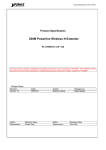
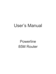
Powerline Network
Instant Networks for Internet Access…and More!
Solution for SOHO, SMALL OFFICE AND HOME OFFICE
Encryption Management Utility
User Guide
for
Powerline Ethernet Bridge 85Mbps
1
Index
Introduction...................................................................... 3
1.
1.1.
1.2.
2.
Installation............................................................................................................................. 3
Run the Utility....................................................................................................................... 4
How to use ....................................................................... 5
2.1.
2.2.
2.3.
2.4.
Main Frame ........................................................................................................................... 5
Privacy Frame ....................................................................................................................... 9
Diagnostics Frame............................................................................................................... 10
About Frame ....................................................................................................................... 12
2
1. Introduction
The Configuration Utility enables the user to find HomePlug devices on the Powerline
network, measures data rate performance, ensures privacy and performs diagnostics by
setting user defined secure Powerline networks.
1.1. Installation
First step, you need to verify that there is no other Powerline Encryption Management
Utility installed on your computer before installing this utility. If there is another utility
installed, please uninstall it and restart your computer.
Second step, please insert setup CD-ROM into the computer’s CD-ROM drive. Run
the “Setup.exe” to install the Utility. The CD will launch an installation screen shown in
Figure 1. Click the “Next” button to continue and follow the instruction to complete the
installation.
Figure 1: Installation Screen
3
1.2.
Run the Utility
After installed the utility, please run the utility from Start / All Programs or double-click
the utility icon on the desktop. Figure 2 is the main frame screen of the configuration utility.
This screen shows a HomePlug 1.0 device connected as a local device and another three
devices as remote devices.
Figure 3 is the main screen that High Speed device connected locally.
Figure 2: Main Screen with HomePlug 1.0 device Local
Figure 3: Main Screen with High Speed device Local
4
2. How to use
There are four Tabs ( Main, Privacy, Diagnostics, About ) on the Utility left top. Each
Tab will launch the different frame and provide different functions. Follows will introduce
the all functions by frame.
2.1.
Main Frame
The Main frame will list all Powerline devices logically connected on the same
Powerline network.
Upper Window
The upper window shows the all local HomePlug devices connected to your
computer. In most cases, there is only one device shown on the window. If you have
more than one NIC (Network Interface Card) on your computer and also connect to
HomePlug devices, you will find more than one local HomePlug devices shown on
the upper window. However, if you have also HomePlug USB device connected at
the same time, you will find more than one local HomePlug devices, too. You can
select one device and click the “Connect” button to manage the Powerline setting.
The status area, above the “Connect” button, will show the local device you
selected. The utility will scan the power line periodically to search all HomePlug
devices.
Lower Window
The lower window lists all the HomePlug devices, discovered on the current logical
Powerline networks. The window will report the connectivity and status.
Figure 4 shows the main frame. There are two local devices connected to the
computer and three devices on the same Powerline networks.
5
Figure 4: The main frame screen
The “Device Name” column shows the default device name. You can change
the name by clicking the “Rename” button.
The “Password” column shows the device password. You can input the
password by clicking the “Enter Password” button.
The “Quality” column shows the remote device’s link quality with the local
device.
The “Rate(Mbps)” column shows the device’s connecting performance with the
local device you selected.
The “MAC Address” column shows the device’s MAC address.
“Rename” button
Please select the device you want to edit the name and click the “Rename” button
to edit the device name on the “name” column directly.
“Enter Password” button
If you want to create a private network, you need to enter the device password first.
Please click on the device you selected and then click the “Enter Password” button,
the dialog box will appear as shown in Figure 5. The selected device name is shown
above the field for entering the password. After entered the password, please click
“OK” button. The confirmation box will notice the password you entered correct or not.
If not, please check the device password and re-try again.
6
Figure 5: Set Device Password
“Add” button
The “Add” button is used to add a remote device to your logical network that is not
in the list displayed on the lower window. For Example, a device is in another logical
network currently. You can click on the “Add” button to add the device to your logical
network. The dialog box shows in Figure 6 after click on the “Add” button, it allows
you to enter both of the device name and the password. The device can join to your
logical network only when the password is correct. And also, the device name will be
changed to the name you entered. The confirmation box will notice success or not. If
not, please check the device password and also the device in the same Powerline
network, and then re-try again.
Figure 6: Add Remote Device
7
“Scan” button
The “Scan” button is used to search for the HomePlug devices connected to your
logical network immediately. By default setting, It will scan every few seconds and
updates the display lists automatically. The screen after entered the name and
password will show as Figure 7.
Figure 7: Main frame screen of the Configuration Utility
8
2.2.
Privacy Frame
All of the HomePlug devices generally use a default logical network name
“HomePlug”. The “Privacy” frame provides a function to manage the logical network and
support you additional security. You can change the network name to the private network
name.
“Use Default (Public Network)” button
You can set the network name to the public one by entering “HomePlug” as the
network name or click on the “Use Default (Public Network)” button, and then press
the “Set Local Device Only” button or “Set All Devices” button.
Figure 8: Privacy Frame Screen
“Set Local Device Only” button
The “Set Local Device Only” button is used to change the network name of the
local device only. After changed the network name, all of the devices existing before
will no longer be able to communicate or respond to you.
“Set All Devices” button
The “Set All Devices” button is used to change the logical network of all devices that
showed on the Diagnostics frame with the correct password.
9
2.3.
Diagnostics Frame
The Diagnostics frame shows the system information and the history of all devices that
have been found before. It is shown as in Figure 9.
The upper window of Diagnostics frame shows the technical data of software and
hardware on the host computer used to communicate over HomePlug. It includes the
following:
z Operating System Type/Version
z Host Network Name
z User Name
z MAC Address of all NICs (network interface card)
z Identify versions of all Driver DLLs and Libraries used (NDIS) and optionally
z Device manufacturer name (Only high speed devices)
z MAC Firmware Version (Only high speed devices)
z Vendor name
Figure 9: Diagnostics Frame Screen
The lower window of Diagnostics frame contains the history of all remote devices
that have been found before on the computer. All the devices will be shown here
regardless of they are on the same logical network name or not. If the devices are on the
same logical network, they will show a transfer rate in the Rate column. If the devices are
on other logical networks or devices are no longer exist, they will show as “?” in the Rate
10
column. The following remote device information is available from the list:
z Device Name
z MAC Address
z Password
z Last known rate
z Last Known Network
z Device manufacturer name
z Date that device last scanned.
z MAC Firmware Version. (Only high speed devices)
The diagnostics information displayed on the upper and lower window could be saved
to a text file, or print. Devices that are no longer existed in the network can be deleted via
the “Delete…” button, too.
“Delete…” button
Please select the device that is no longer existed in the network and click on this
button to delete the device record.
“View Report…” button
Please click on this button to view all the device information displayed on the upper
and lower window by the default text editor.
“Save Report…” button
You can click on this button to save all the device information displayed on the
upper and lower window to a text file directly.
“Print Report…” button
You can click on this button to print the all diagnostics information to your default
printer directly.
11
2.4. About Frame
The About Frame shows the software version .
Preferences window
The lower window shows the option for you to turn on the “Auto Scan” feature or off. It
is shown as Figure 10. The default setting is “on”. If you turn off the “Auto Scan” feature,
the main frame will not scan the all devices automatically. You need to click the “Scan”
button in the main frame to search for the devices manually.
Figure 10: About Frame Screen
12