Download USER'S GUIDE
Transcript
USER’S GUIDE Highpowered and programmable Switching Power supply Model IT6512/IT6513 IT6512A/6513A/6522A/ IT6502D/IT6512D Copyright 2005 All Rights Reserved Ver1.0/Jan, 2011/ IT6512-1001 1 About your safety .................................................................................................................. 3 General information .......................................................................................................................................... 3 Protection from electric shock......................................................................................................................... 3 Definition of user ............................................................................................................................................... 3 Certification and Warranty .................................................................................................... 4 Certification ........................................................................................................................................................ 4 Warranty............................................................................................................................................................. 4 Limitation of Warranty ...................................................................................................................................... 4 Introduction ........................................................................................................................... 5 Chapter1 Inspection and Installation ..................................................................................... 6 1.1 Inspection .................................................................................................................................................... 6 1.2 Dimension ................................................................................................................................................... 6 Chapter2 Quick start ............................................................................................................. 9 2.1 Description of front panel and rear panel ............................................................................................... 9 2.2 keyboard introduction .............................................................................................................................. 10 2.3 VFD indicator lamps description ............................................................................................................ 11 Chapter3 power-on inspection ............................................................................................ 12 3.1 power on pre-examination ...................................................................................................................... 12 3.2 Output checkout ....................................................................................................................................... 13 Chapter4 Specification ........................................................................................................ 14 4.1 Main technical parameters ..................................................................................................................... 14 4.2 Supplemental characteristics ................................................................................................................. 17 Chapter5 Basic Operations ................................................................................................. 17 5.1 Local/Remote............................................................................................................................................ 18 5.2 Setting voltage .......................................................................................................................................... 18 5.3 Setting current .......................................................................................................................................... 18 5.4 On/off button ............................................................................................................................................. 18 5.5 Setting value/Actual value ...................................................................................................................... 19 5.6 Voltage and current adjustment ............................................................................................................. 19 5.7 Save operation ......................................................................................................................................... 19 5.8 Trigger operation ...................................................................................................................................... 19 5.9 Menu Operation........................................................................................................................................ 19 5.10 Protection Function................................................................................................................................ 33 5.11 Rising time and Fall time setup ............................................................................................................ 33 5.12 Key Lock Function ................................................................................................................................. 34 5.13 Rear terminal functions ......................................................................................................................... 34 5.14 Analogue interface ................................................................................................................................. 34 Connection and Setup ........................................................................................................ 35 Chapter6 Remote Control ................................................................................................... 37 6.1 RS232 interface........................................................................................................................................ 37 6.2 USB interface............................................................................................................................................ 39 6.3 GPIB Interface .......................................................................................................................................... 39 6.4 RS485 Interface ....................................................................................................................................... 39 2 About your safety Pease review the following safety precautions before operating our equipment. General information The following safety precautions should be observed before using this product and any associated instrumentations. Although some instruments and accessories would be used with non-hazardous voltages, there are situations where hazardous conditions may be present. This product is intended for use by qualified personnel who recognize shock hazards and are familiar with the safety precautions required to avoid possible injury. Read and follow all installation, operation, and maintenance information carefully before using the product. Refer to this manual for complete product specifications. If the product is used in a manner not specified, the protection provided by the product may be impaired. Before performing any maintenance, disconnect the line cord and all test cables. Protection from electric shock Operators of this instrument must be protected from electric shock at all times. The responsible body must ensure that operators are prevented access and/or insulated from every connection point. In some cases, connections must be exposed to potential human contact. Product operators in these circumstances must be trained to protect themselves from the risk of electric shock. If the circuit is capable of operating at or above 1000 volts, no conductive part of the circuit may be exposed. Definition of user Responsible body is the individual or group responsible for the use and maintenance of equipment is operated within its specifications and operating limits, and for ensuring that operators are adequately trained. Operators use the product for its intended function. They must be trained in electrical safety procedures and proper use of the instrument. They must be protected from electric shock and contact with hazardous live circuits. Service is only to be performed by qualified service personnel. Safety symbols and terms Connect it to safety earth ground using the wire recommended in the user manual. The symbol on an instrument indicates that the user should refer to the operating instructions located in the manual. High voltage danger 3 Certification and Warranty Certification We certify that this product meet its published specifications at time of shipment from the factory. Warranty This instrument product is warranted against defects in material and workmanship for a period of one year from date of delivery. During the warranty period we will, at its option, either repair or replace products which prove to be defective. For warranty service, with the exception of warranty options, this product must be returned to a service facility designated by us. Customer shall prepay shipping charges by (and shall pay all duty and taxes) for products returned to the supplier for warranty service. Except for products returned to customer from another country, supplier shall pay for return of products to customer. Limitation of Warranty The foregoing warranty shall not apply to defects resulting from improper or inadequate maintenance by the Customer, Customer-supplied software or interfacing, unauthorized modification or misuse, operation outside of the environmental specifications for the product, or improper site preparation and maintenance. 4 Introduction IT6500 series is a flexiable range single output high power supply.With wide power ranges from 800W to 6KW,currents from 30A to 240A.Standard RS232,USB, GPIB,RS485 and LAN interfaces included on the rear panel provide flexibility for remote operation of the power supply.Its compact 1U(1200W) to 4U(6KW) size form factor makes it ideal for use in a standard 19-inch rack.IT6500 series is specially designed for automobile electronic industry.It provides built-in DIN40839 and ISO16750-2 waveforms to test the anti-jamming performance of products,such as DVD and sound equipment. (1)Auto-Range function (2)High Resolution Display (1mV/1mA) (3)RS232/USBTMC/GPIB/RS485/LAN standard interfaces (4)Analog Control Interface (5)Master/Slave Mode for Series/Parallel connectivity (6)Adjustable voltage slope (rise and fall time) (7)Sequence programming (List mode) (8)Built-in DIN40839 and ISO16750-2 waveform (8)OVP and OPP protection (9)Intelligent fans control Model IT6502D IT6512 IT6513 IT6512A IT6513A IT6512D IT6522A Model Voltage 80V 80V 150V 80V 150V 80V 80V LIST Master-Slave Current 60A 60A 30A 60A 30A 120A 120A Power 800W 1200W 1200W 1200W 1200W 1600W 3000W External Analog control IT6502D × √ √ IT6512 √ √ √ IT6512A × √ √ IT6512D × √ √ IT6513 √ √ √ IT6513A × √ √ IT6522A × √ √ DIN40839 &ISO16750-2 × √ × × √ × × 5 AC input 110V/220V AC 110V/220V AC 110V/220V AC 110V/220V AC 110V/220V AC 110V/220V AC 110V/220V AC Dimension 1U 1U 1U 1U 1U 2U 2U Communication interface RS232/RS485/USB/G PIB RS232/RS485/USB/G PIB RS232/RS485/USB/G PIB RS232/RS485/USB/G PIB/LAN RS232/RS485/USB/G PIB RS232/RS485/USB/G PIB RS232/RS485/USB/G PIB/LAN Chapter1 Inspection and Installation Power supply is a equipment with high grade of security.It has a protective earth terminal.Please note the security label and instructions in the manual. 1.1 Inspection The following steps help you verify that the power supply is ready for use. 1.check the appearance If you find any damage of the panel or outline border,please contact with the local franchisers of ITECH or the service department.Before you get a positive answer,please do not return the unit. 2.check the accessories To verify that you have received the following items along with your power supply.If something is missing,please contact with the nearest franchisers. □ power cord fit for your local voltage standard (except IT6522A and IT6512D) □ user’s manual. □ calibration report □ USB cable 3.AC input Support two kinds of AC input voltage:110VAC and 220VAC.There is no need to switch the input mode. AC input grade: Option Opt.01: 220VAC ± 10%, 47 to 63 Hz Option Opt.02: 110 VAC ± 10%, 47 to 63 Hz Note:IT6522A and IT6512D can not reach the full power output in 110Vac input level. 1.2 Dimension The dimension of IT6512/IT6513/IT6512A/IT6513A/IT6502D 415mmW×44mmH×500mmD Refer to the following dimension drawing: (front view) 6 (side view) unit:millimeter(mm) IT6512/IT6513/IT6512A/IT6513A/IT6502D Dimensional Drawing The Dimension of IT6522A/IT6512D 439mmW×90mmH×500mmD 7 IT6522A/IT6512D dimensional drawing 8 Chapter2 Quick start This chapter will introduce the front panle,rear panel,keyboard function and VFD display functions.To ensure you have a quick understanding of this product before you using it. 2.1 Description of front panel and rear panel IT6512/IT6513/IT6512A/IT6513A/IT6502D front panel IT6522A/IT6512D front panel 1. 2. 3. 4. power supply switch VFD display board pulsating knob to control voltage,coarse button,fine botton pulsating knob to control current,coarse button,fine botton 5. 6. key directioin key and function keys and composite key 7. numeric key and key IT6512/IT6513/IT6512A/IT6513A/IT6502D rear panel 9 IT6522A/IT6512D rear panel 1. 2. 3. 4. 5. 6. 7. 8. 9. 10. 11. remote sense and ouput terminals output terminal RS485 communication interface Fuses Analog control interface Cooling fans GPIB communicaiton interface USB communicaiton interface RS232 communicaiton interface AC power input socket Ethernet communication interface 2.2 keyboard introduction Keyboard instructions as follows: keys Name and functions 0-9 Numeric button Composite key OVP setting button,the button used to set the ovp value/menu function button Menu which used to set the related parameters of power supply Voltage setting button,used to set the ouput voltage value/set the rising time V-set Slope and fall time of voltage 10 I-set Pmax Recall Save Meter Local Enter Trigger On/Off Lock Current setting button,used to set the output current value/set the maximum power value Callback button,used to recall a saved setting parameter/save button,used to save a setting parameter Meter button,used to switch the display between actual value and setting value /switch to the loacl mode Confirm button,to confirm the setting numbers or functions/trigger button,used to provide a trigger single for list operation Ouput on/off button,used to control the output status of power supply/kelock function button,used to lock the front panel buttons Left and right direction button,used to adjust the location of the cursor Up and down direction button,used to select the items of the menu or increase(decrease) the output voltage and current value Confirm button Quit buttion 2.3 VFD indicator lamps description As follows: chart function description chart function description OFF Power supply in off mode Timer none CV Power supply in CV mode Sense none CC Power supply in CC mode Ext none * Open the keylock function Adrs none Meter “Meter” buttion in on mode Rmt Remote control mode Shift using composite function Error Error occur OVP Open the OVP function Prot Protections for OV or OT OCP none Lock none 11 Chapter3 power-on inspection This chapter will introduce the power-on check procedure to ensure the unit is ready for use.It includes two parts:pre-check and output check. 3.1 power on pre-examination Power on pre-examination includes two parts:initial power supply and system selftest. 2) Initial power source Use the following steps to help solve problems you might encounter when turning on the instrument.If the unit can not be started normaly,please check according to the following guidance. 1) Verify that there is AC power to the power supply First, verify that the power cord is firmly plugged into the power receptacle on the rear panel of the power supply. You should also make sure that the power source you plugged into the power supply is energized. Then, verify that the power supply is turned on 2)Verify that the correct power-line fuse is installed. If the fuse was damaged, please see the table below to replace the fuse for your power supply model Fuse specification Fuse specification (110VAC) (220VAC) IT6512 15A 250V 15A 250V IT6513 15A 250V 15A 250V IT6512A 15A 250V 15A 250V IT6513A 15A 250V 15A 250V IT6522A 20A 250V 20A 250V IT6502D 15A 250V 15A 250V IT6512D 20A 250V 20A 250V 3) The way to change the fuse Open the plastic lid in the below of the power input socket,you will see the fuse,and then exchange a good fuse according to the above specification. 2.System selftest When you turn on the power supply,it will do the system selftest. If the EEPROM was damaged, the VFD will display as follows: EEPROM FAILURE If the latest operation data in EEPROM is lost, the VFD will display as follows: Config Data Lost If the calibration data in EEPROM is lost, the VFD will display as follows: Calibration Data Lost If the factory calibration data in EEPROM is lost, the VFD will display as follows: FactoryCal.Data Lost 12 If the system setting data in EEPROM is lost,the VFD will display as follows: MainframeInitializeLost If all is normal,the VFD will display the voltage and current as the following status: OFF 0.000V 0.0W 0.000A Warning: The power supply is shipped from the factory with a power-line cord that has a plug appropriate for your location. Your power supply is equipped with a 3-wire grounding type power cord; the third conductor being the ground. The power supply is grounded only when the power-line cord is plugged into an appropriate receptacle. Do not operate your power supply without adequate cabinet ground connection. 3.2 Output checkout The following procedures help to check and ensure that the power supply develops its rated outputs and properly responds to operations on the front panel. 1 Voltage Output Checkout The following steps verify basic voltage functions without load. 1) Turn on the power supply 2) Set the ouput current(≥0.1A) 3) Open the ouput Press on/off button,the CV indicator lamp will be lit. 4) Open the Meter button 5) Set the ouput voltage Set different voltage and check whether the VFD display voltage is approximate to the setting voltage. 6) Ensure the output voltage can be adjusted from 0V to full rated value 2.Output current checkout The following steps check basic current functions with a short across the power supply’s output 1) Turn on the power supply. 2) Disable the output 3) 4) 5) 6) 7) Press On/Off key to ensure that the output is disabled. Connect a short across (+) and (-) output terminals with an insulated test lead. Use a wire size sufficient to handle the maximum current. Enable the output and open the Meter function button To ensure the CC indicator lamp is lit Adjust the current Set different current values and check whether the voltage display is approximate to 0V,the display current value is approximate to the setting value Ensure that the current can be adjusted from zero to the full rated value. Turn off the power supply and remove the short wire from the output terminals. 13 Chapter4 Specification This chapter will introduce the rated voltage,current,power and many other main parameters of IT6500 series. 4.1 Main technical parameters parameters Rated value ( 0 °C - 40 °C) ( in remote sense mode) Load regulation ±(%of*output+offset ) Line regulation (%of output+offset) Setting resolution Readback resolution Setting accuracy (within twelve months)(25°C±5°C) (%of output+offset) Readback accuracy (25°C±5°C) (%of output+offset) IT6512 IT6513 voltage current power voltage 0~80V 0~60A 0~1200W <0.01%+8mV 0-150V 0-30A 0-1200W <0.05%+30mV current ≤0.1%+10mA ≤0.1%+30mA voltage current voltage <0.02%+2mV <0.02%+2mA <0.02%+20mV <0.02%+10mA 1mV 3mV current voltage current 1mA 1mV 1mA 1mA 3mV 1mA voltage ≤0.02%+30mV ≤0.05%+30mV current ≤0.1%+0.1%FS ≤0.2%+0.1%FS voltage ≤0.02%+30mV ≤0.05%+30mV current ≤0.1%+0.1%FS ≤0.2%+0.1%FS voltage ≤30mVp-p ≤60mVp-p (20Hz ~20MHz) current ≤20mArms ≤40mArms Tem coefficient (0 °C ~ 40 °C) ±( % of output+offset) Readback Tem coefficient ±( % of output+offset) voltage 0.02%+30mV <0.02%+30mV current ≤0.05%+10mA ≤0.05%+10mA voltage 0.02%+30mV <0.02%+30mV current ≤0.05%+5mA ≤0.05%+5mA Ripple dimension(mm) 415mmW×44mmH×500mmD 415mmW×44mmH×500mmD weight(Kg) 8.5Kg 8.5Kg 14 parameters Rated value ( 0 °C - 40 °C) ( in remote sense mode) Load regulation ±(%of*output+offset ) Line regulation (%of output+offset) Setting resolution Readback resolution Setting accuracy (within twelve months)(25°C±5°C) (%of output+offset) Readback accuracy (25°C±5°C) (%of output+offset) IT6512A IT6522A voltage current power voltage 0~80V 0~60A 0~1200W <0.01%+8mV 0-80V 0-120A 0-3000W <0.05%+30mV current ≤0.1%+10mA ≤0.1%+30mA voltage current voltage <0.02%+2mV <0.02%+2mA <0.02%+20mV <0.02%+10mA 1mV 2mV current voltage current 1mA 1mV 1mA 3mA 2mV 3mA voltage ≤0.02%+30mV ≤0.05%+30mV current ≤0.1%+0.1%FS ≤0.2%+0.1%FS voltage ≤0.02%+30mV ≤0.05%+30mV current ≤0.1%+0.1%FS ≤0.2%+0.1%FS voltage ≤30mVp-p ≤80mVp-p (20Hz ~20MHz) current ≤20mArms ≤120mArms Tem coefficient (0 °C ~ 40 °C) ±( % of output+offset) Readback Tem coefficient ±( % of output+offset) voltage ≤0.02%+30mV <0.02%+30mV current ≤0.05%+10mA ≤0.05%+10mA voltage ≤0.02%+30mV <0.02%+30mV current ≤0.05%+5mA ≤0.05%+10mA Ripple dimension(mm) 415mmW×44mmH×500mmD 439mmW×90mmH×534mmD weight(Kg) 8.5Kg 17Kg 15 parameters voltage Rated value current ( 0 °C - 40 °C) power ( in remote voltage sense mode) Load regulation ±(%of*output+ offset) Line regulation (%of output+offset) IT6513A IT6502D IT6512D 0~150V 0~30A 0~1200W <0.05%+30mV 0~80V 0~60A 0~800W <0.01%+8mV 0-80V 0-120A 0-1600W <0.05%+30mV current ≤0.1%+30mA ≤0.1%+10mA ≤0.1%+30mA voltage <0.02%+20mV ≤0.02%+2mV <0.02%+20mV current <0.02%+10mA <0.02%+2mA <0.02%+10mA voltage 3mV 1mV 2mV current voltage current 1mA 1mV 1mA 1mA 1mV 1mA 3mA 2mV 3mA voltage ≤0.05%+30mV current ≤0.2%+0.1%FS ≤0.1%+0.1%FS ≤0.2%+0.1%FS voltage ≤0.05%+30mV ≤0.02%+30mV ≤0.05%+30mV current ≤0.2%+0.1%FS ≤0.2%+0.1%FS ≤0.2%+0.1%FS voltage ≤60mVp-p ≤30mVp-p ≤80mVp-p (20Hz ~20MHz) current ≤40mArms ≤20mArms ≤120mArms Tem coefficient (0 °C ~ 40 °C) ±( % of output+offset) Readback Tem coefficient ±( % of output+offset) voltage ≤0.02%+30mV ≤0.02%+30mV <0.02%+30mV current ≤0.05%+10mA ≤0.05%+10mA ≤0.05%+10mA voltage ≤0.02%+30mV ≤0.02%+30mV <0.02%+30mV current ≤0.05%+5mA ≤0.05%+5mA ≤0.05%+10mA Setting resolution Readback resolution Setting accuracy (within twelve months) (25°C±5°C) (%of output+offset) Readback accuracy (25°C±5°C) (%of output+offset) Ripple dimension (mm) weight(Kg) ≤0.02%+30mV 415mmW×44mmH×500mmD 415mmW×44mmH×500mm D 8.5Kg 8.5Kg 16 ≤0.05%+30mV 439mmW×90mmH×534mmD 17Kg 4.2 Supplemental characteristics State storage capacity 100 sets Recommended calibration frequency once a year Cooling style fans Operation Temperature 0 to 40 °C Storage Temperature -20 to 70 °C. Environmental Conditions Designed for indoor use and operated at maximum relative humidity of 95% Chapter5 Basic Operations This chapter describes in detail the use of the front-panel keys and shows how they are used to accomplish power supply operation. This chapter is divided into the following sections: Local mode/Remote mode Setting voltage Setting current On/off Actual value display/setting value dislay Adjustment of current/voltage/power Save operation Trigger operation Menu operation Protection function Setting rising time and fall time of voltage Keylock function Functions of rear terminals Anolog interfaces 17 5.1 Local/Remote You can switch from remote mode to local mode by press + buttons. When you turn on the unit,it will default in local mode and all buttons are available.That’s to say,in remote mode,the front panel buttons can not be used.The two operating mode can be switched through PC.When the operating mode is changed,all the output parameters will not be effected. 5.2 Setting voltage The constant voltage range is from 0V to the maximum voltage value. It is very easy for you to set the constant voltage output. You have 3 solutions to set the constant voltage value.And when you press V-set ,this button will be lit. (1)directly input through number keys Input the value you want to set and then please press (2)using knob to set value Press V-set or button to confirm. button Press button(coarse adjustment,change the value in integer bit) or adjustment,change the value in decimal bit),and then rotate the knob to set the value (3)using left and right direction key to set value Press V-set button(fine button Press button(coarse adjustment,change the value in integer bit) or button(fine adjustment,change the value in decimal bit),and then through left and right keys to adjust the cursor location,press ▲and ▼ to set the voltage value 5.3 Setting current The constant current range is from 0A to the maximum voltage value. It is very easy for you to set the constant current output. You have 3 solutions to set the constant current value.And when you press I-set ,this button will be lit. (1)directly input through number keys Input the value you want to set and then please press (2)using knob to set value Press I-set or button to confirm. button Press button(coarse adjustment,change the value in integer bit) or adjustment,change the value in decimal bit),and then rotate the knob to set the value (3)using left and right direction key to set value Press I-set button(fine button Press button(coarse adjustment,change the value in integer bit) or button(fine adjustment,change the value in decimal bit),and then through left and right keys to adjust the cursor location,press ▲and ▼ to set the current value 5.4 On/off button On/Off button is used to control the output state of power supply. If On/Off button is lit,this represents output is open.And in on mode,the indicator lamp(CC/CV) will be lit. Note:please ensure that the DC source and product under test have been connected well before you press On/Off button. 18 5.5 Setting value/Actual value Meter button is used to switch the display between actual value and setting value.When Meter button is lit,this represents that VFD board display is actual value.Reversely,if Meter button is dark,VFD board display is corresponding to setting value. 5.6 Voltage and current adjustment Power supply’s output voltage and Electronic load’s resistance determine the output current.Only when the actual current value is lower than the setting current value,can the power supply works in CV mode.And the CV indicator lamp will be lit. If the actual current value is limited by the setting current value or rated current,then IT6512 will change to CC mode.And the CC indicator lamp will be lit. 5.7 Save operation IT6512 can enable you to save some often used parameters in nonvolatile memory up to 100sets.So that you can recall the parameters quickly.The following ways can help you achieve the save and recall + Recall (Save) button or through command operations:by pressing composite button *SAV,*RCL.Save operation should work in with GROUP.Each GROUP can save 10sets,IT6512 includes 10 GROUP from 0-9. Save parameters include setting voltage and setting current Save method: + Recall +number keys 1…9,and then pressing Enter button to Using composite button save the preset value into specified memory region. Using Recall button +number keys 1-9,and then pressing Enter button to recall the saved parameters from specified memory region. 5.8 Trigger operation Please select the trigger mode in the menu setup before you start a trigger operation. Before you want to run a list sequence file,please provide a trigger signal by press composited button + Enter (trigger).During the list file running,the button Enter (trigger) will be alight. 5.9 Menu Operation 1. Menu description Press + (Menu) to enter the menu function.View the meun in VFD,and use right and left direction key or knob to scroll through the complete menu list as following.If press Enter button,you could get the selected menu function.Press 19 back to the previous menu selection page. Menu of IT6512 and IT6513 Initialize Power On Trigger Memory Buzzer Communication Rst(Def) Sav0 Manual(Def) Bus Memory Group = 0 On(Def) Off RS232(Def) System menu Initialize the system Set power on parameters Restore to factory defaults Remian last shutdown parameters Manual trigger Bus trigger Work with recall button to recall 100sets saved parameters 0:represents 1-10sets; 1:represents:11-20sets, by parity of reasoning enable the buzzer function disable the buzzer function Select the communication interface Select RS232 communication interface 4800, 8, None parity 1 , Addr... 9600 Odd parity (0~31) 19200 Even parity 38400 57600 115200 DEVICE MENU USB GPIB SYSTEM RS485 Select USB communication interface Select GPIB communication interface Addr=0 set the communication address Select RS485 communication interface 4800, 8, None parity, 1 , Addr... 9600 Odd parity (0~31) 19200 Even parity 38400 57600 115200 OFF Enables automatic delay to switch display from setting to measured value (meter). Return Meter function disabled. Delay Enables return meter function P-On output Power whether power supply was on Off(def) After power on,the instrument will be in the off state. Last If output was on prior to turning the power off,the ON state will be ReturnMeter P-Out 20 resumed after power on. Sense-Protect Load Ext-Ctrl mode and related parameter setting Config Limit Online connection mode OCP Func LIST Enable(Def) Enable sense protection function Disable Disable sense protection function Off Enables dummy load to increase speed of voltage fall time. Disables the dummy load (default). On Enables the dummy load. 10v-M 10V/10K-P 10V/5V monitoring mode options 10V/10K or 5V/5K setting mode selection Voltage(resistance)setting mode selection Disable this function Minmum voltage setting Load setup V-P Off Vmin=1.000V Vmax=80.000 V Parallel Series Master Slave Addr… Off On Off On Off Recall Recal List Recall list file= 1 EditList EditSeq DIN40839 ISO16750-2 DIN40839 12V 24V Off On ISO16750-2 Profile Short voltage drop 21 Maximum voltage setting Parallel connection Series connection Act as a master Act as a slave Address Disable this function Enable this function Disable over current protection function Enable over current protection function Quit list mode Recall list file Select the list file number Edit list operation Edit sequence operation Evaluation of automobile waveform starting Select the 12V or 24V system Enable/Disable DIN40839 function This test simulates the effect when a conventional fuse element melts in another circuit 12V 24V Off Profile for the reset test Starting profile INFO informati on about this machine Note:press Select 12V or 24V system Enable or Disable the Short voltage drop function. On This test verifies the reset behaviour of the DUT at different voltage drops. This test is applicable to equipment with reset function The minmum supply voltage Usmin Usmin Off Enable/Disable this function On This test verifies the behaviour of a DUT during and after cranking. 12V Select 12V or 24V 24V test system Set the levels/voltages/dur ation of starting 1 profile Set the cycle Repeat times(1-100) Delay Set the delay time Off Enable/Disable this function On Model:IT6512 Ver:1.00-1.00 SN:0123456789A F model,software version,SN No Information Exit Menu Reserved for calibration information Quit menu operation + operation.Besides,press (Menu)to view the menu items,press to quit menu button can enable you quit the function operation state. 22 IT6512A/IT6513A/IT6522A/IT6502D/IT6512D System menu Initialize Power On Trigger Memory Buzzer Communication Rst(Def) Sav0 Manual(Def) Bus Memory Group = 0 On(Def) Off RS232(Def) Initialize the system Set power on parameters Restore to factory defaults Remian last shutdown parameters Manual trigger Bus trigger Work with recall button to recall 100sets saved parameters 0:represents 1-10sets; 1:represents:11-20sets, by parity of reasoning enable the buzzer function disable the buzzer function Select the communication interface Select RS232 communication interface 4800, 8, None parity 1 , Addr... 9600 Odd parity (0~31) 19200 Even parity 38400 57600 115200 DEVICE MENU SYSTEM USB GPIB RS485 Select USB communication interface Select GPIB communication interface Addr=0 set the communication address Select RS485 communication interface 4800, 8, None parity, 1 , Addr... 9600 Odd parity (0~31) 19200 Even parity 38400 57600 115200 ETHERNET Select Ethernet communication interface Gateway=192.168.0.1 This item is setable IP=192.168.0.125 This item is setable Mask=255.255.255.0 This item is setable Socket Port=30000 This item is setable Enables automatic delay to switch display from setting to measured value (meter). ReturnMeter 23 P-Out Sense-Protect Load Ext-Ctrl mode and related parameter setting Config Limit Online connection mode OCP INFO informati on about this machine OFF Return Meter function disabled. Delay Enables return meter function P-On output Power whether power supply was on Off(def) After power on,the instrument will be in the off state. Last If output was on prior to turning the power off,the ON state will be resumed after power on. Enable(Def) Enable sense protection function Disable Disable sense protection function Off Enables dummy load to increase speed of voltage fall time. Disables the dummy load (default). On Enables the dummy load. 10v-M 10V/10K-P 10V/5V monitoring mode options 10V/10K or 5V/5K setting mode selection Voltage(resistance)setting mode selection Disable this function Minmum voltage setting Load setup V-P Off Vmin=1.000V Vmax=80.000 V Parallel Series Master Slave Addr… Off On Off On Maximum voltage setting Parallel connection Series connection Act as a master Act as a slave Address Disable this function Enable this function Disable over current protection function Enable over current protection function Model:IT6512 Ver:1.00-1.00 SN:0123456789A F model,software version,SN No Information Exit Menu Reserved for calibration information Quit menu operation 24 2.Menu function Output voltage set(>Vmax,Vmin) The voltage can be set between 0A and rated voltage.Pressing + (Menu) to entry into Config item,and then using knob or direction keys to select Vmin option under Limit item.Press Enter button,then set the minmum voltage.After pressing Enter button,you could set the maximum voltage.After the setting operation,the voltage can only be adjusted within the limitation of Vmin and Vmax. Default Vmax value is the rated voltage,and Vmin is 0V. Communication Set(>Communication ) Under this item,you can set the concrete communication mode.This unit has provided multiple communication interfaces:RS232/USB/GPIB/RS485.Of which,the GPIB are addressable from 0-31.The baudrate options of RS232 are 4800,9600,19200,38400,57600,11.52K.Data bit is 8bits.Parity bit has three options:NONE,ODD,EVEN.Please ensure the configuration consistency between our instrunment and PC,so that you could have a successful communication. Key Sound Set(>Buzzer) This item can set the buzzer state.On option indicates that when you push buttons,the buzzer will sound.OFF option indicates that the buzzer function is disabled.Factory default is On option. Trigger Mode(>Trigger) This item is used to set the trigger source,to be Manual tigger mode or Bus trigger mode.It often be used to provide a trigger signal for a list operation.In Manual option,press + Enter (Trigger) could generate a trigger signal.If in BUS option,this indicates in BUS trigger mode.Factory default is Manual option., Save Group Operation(Memory) Power source can save 100sets parameters in nonvolatile memory by the save group setting.This operation provides the customer with a convenient and quick save/recall using condition. + Recall (Save)+0-9 numeric GRP0:save(recall) power source parameters in 0-9 sets.Press keys( Recall +0-9 numeric keys to recall the parameters) GRP1:save(recall) parameters in 10th -19th sets.Press + Recall (save)+numbers1-9 to save the parameters( Recall +numbers1-9 to recall parameters).Under this condition,number “1” represents to save or recall the 10th parameters.Number “2” represents to save or recall the eleventh parameter.GRP2-GRP9 can be understanded in the same manner. 25 Initialize setting(> Initialize ) This item can enable all setup of the menu to factory default.Press to confirm. Configure Power-On State(>Power-on) The initial power-On state of the power supply can be configured by following the steps below: 1. From the SYSTEM menu, select Power‐On and press enter. 2. There are two options: Rst(Def) – Factory Default. Sav0 – Settings before last power up. 3. Select the settings you want during power up, and press enter to save changes. 4. To exit the menu at any time, press esc button twice. Return to Meter state(> Return Meter) This option allows users to enable an internal fixed timer delay (5 seconds) for the power supply to automatically switch from setting display to measured display. When enabled, if the power supply output state is ON (enabled) and if the display shows setting voltage and current, it will automatically switch to measured voltage and current display after 5 seconds. The backlight of the Meter button will also be lit. In this state, pushing Meter button again to toggle back to setting display will reset the 5-second timer again before the supply changes back to measured display. Load Setup Option (<Load) The power supply has an internal dummy load that can be enabled to increase the speed of the voltage fall time for high speed test applications. The effectiveness of this function is dependent on the DUT (device under test) and may or may not be useful for some applications. This feature should only be used with caution, as it is not designed for all applications. DO NOT enable this function for applications such as connecting devices for battery charging or powering electric motors. All other applications that may behave similarly as a load should NOT use this function. This function is disabled by default. 26 List Operation(>List ) Please preset the trigger mode before you run a list file. Press + (Menu) to enter the menu setup.Then press up and down buttons to select Enter item >System,press to confirm.After that,press up and down buttons to select >Trigger item to set the trigger mode,and press enter to confirm. Operation steps 1. Press 2. VFD display SYSTEM,press 3. 4. 5. 6. 7. VFD display OFF,press VFD display File Name xx---,input the sequence file name(1---10) to be edited VFD display List Power =xxxxxW----,input the maximum power value VFD display List Repeat =xxxxx----,input the repeat running times(1---65535) of LIST file VFD display Active Seq:0987654321 ----select the sequence name to be linked in one LIST file.After you select the sequence number,then according number will change to “Y” VFD display Seq n Repeat:xxxxx----,set the repeat runing times of the linked sequence n(1---65535) 8. 9. + (Menu) to enter the menu setup Enter to confirm to select EDITLIST item,press Enter to confirm to select LIST,press or Save list to File?----,press to finish the edit operation Sequence Operation(>Seq ) Please preset the trigger mode before you edit a sequence file Press + item >System,press (Menu) to enter the menu setup.Then press up and down buttons to select Enter to confirm.After that,press up and down buttons to select >Trigger item to set the trigger mode,and press enter to confirm. You could edit various kinds of sequence with variable ouput by setting up every step’s parameters.The parameters includes step-voltage,step-current,step-time and time unit.Besides the fomer parameters,you should also edit whether continue to the next step,repeat times and whether to save the file.After you finish the sequence file edition,if the instrument receives a trigger signal,the sequence file will begin to run until finishing the sequence, or receive another trigger signal.The following will take a three sequence file to be an example: Operation Steps: 1. Press + (Menu) to enter the menu setup 2. VFD display SYSTEM,press 3. VFD display OFF,press 4. VFD display Seq Name: xx,input the sequence name to be edited (1-10) 5. VFD display Active Step:0987654321, activate the sequence steps,when step is activated, to select LIST,press Enter to confirm to select EDITSeq,press Enter to confirm. according number will change to “Y”(for example:select step 1) 6. VFD display Seq Step n Voltage =xxxxxV,set the voltage of activated sequence step(for example:3V) 27 7. VFD display Seq Seq n Current =xxxxxA,set the current of activated sequence step(for example:1A) 8. VFD display Seq Step n Width =xxxxxms,set the duration of time of the activated step(1---65535),(for example:3000ms) 9. VFD display Seq Step n Slope=xxxxxms.Set the voltage rising time of the activated step(0-65535),for example:30ms 10. VFD display Active Step:0987654321,input step number,for example:2 11. VFD display Seq Step n Voltage=xxxxxV,set the voltage of activated sequence step(for example:5V) 12. VFD display Seq Step n Current=xxxxxA, set the current of activated sequence step n(for example:4A) 13. VFD display Seq Step n Width=xxxxxms.for example 3000ms 14. VFD display Seq Step n Slope=xxxxxms,for example 30ms 15. VFD display Active Step:0987654321,for example 3 16. VFD display Seq Step n Voltage=xxxxxV,for example 7V 17. VFD display Seq Step n Current=xxxxxA,for example 8A 18. VFD display Seq Step n Width=xxxxxms,for example 3000ms 19. VFD display Seq Step n Slope=xxxxxms,for example 30ms 20. VFD display Save Seq To File?----Press or button to finish the edition Trigger the sequence file: 1. Press + 2. VFD display SYSTEM,press 3. VFD display OFF,press 4. Press + (Menu) to enter the menu setup to select LIST,press Enter to confirm to select CALLSeq,press Enter to confirm (Trigger) button to give a trigger signal 28 DIN40839 (Specialized function for model IT6512/6513) IT6512/IT6513 models have built in DIN40839 waveform.This test verifies the behaviour of a DUT during and after cranking. DIN40839 for 12V system: Step Voltage (V) Current(A) Width(mS) Slope(mS) 1 4.5 60 15 5 2 6 60 2000 5 3 12 60 10 DIN40839 for 24V system: Steps Voltage (V) Current(A) Width(mS) Slope(mS) 1 8V 60 50 10 2 12 60 2000 5 3 24V 60 10 How to recall “DIN40839 waveform” from menu (take 12V system as a example): 1. Press + (Menu)to enter the menu operation 2. VFD displays SYSTEM CONFIG FUNC. INFO , Press to select FUNC. Press Enter to confirm,then select DIN40839,press Enter to confirm or to select 12V system,press Enter to confirm. 3. Press 4. Press to select Off/On,press or lamp will be lit and display on the VFD. to select On,press Enter to confirm.The Trig indicator to quit menu operation 5. Press 6. VFD will display DIN40839 in the lower right corner 7. Press On/Off ,turn on the output 8. press waveform. + Enter (Trigger)to generate a trigger signal.The DC source will output DIN40839 29 ISO16750-2(Specialized function for model IT6512/6513) IT6512/IT6513 models has built-in ISO16720-2 waveforms.To verify the anti-interference performance of the automotive electronics’ products. 1* Short voltage drop This test simulates the effect when a conventional fuse element melts in another circuit. Apply the test pulse (see Figures below) simultaneously to all relevant inputs (connections) of the DUT. The rise time and fall time shall be not more than 10 ms. 12V system: 24V system: How to recall “Short voltage drop” waveform from menu (take 12V system as a example): 1 Press + (Menu)to enter the menu operation 2. VFD displays SYSTEM CONFIG FUNC. INFO , Press to select FUNC. Press Enter to confirm,then select ISO16750-2,press Enter to confirm or to select Short voltage drop,press Enter to confirm. 3. Press 4 Press or to select 12V system,press Enter to confirm. to select On,press Enter to confirm.The Trig indicating 5 Press to select Off/On,press or lamp will be lit and display on the VFD. 6 7 8 to quit menu operation Press VFD will display Short voltage drop in the lower right corner Press On/Off ,turn on the output + Enter (Trigger)to generate a trigger signal.The DC source will output Short voltage press drop waveform. 9 30 Note:Please make sure the trigger source is selected in MANUAL item in above operations(refer to step 9th).And user need to turn on the internal dummy load to speed up the falling time during ISO16750-2/DIN40839 waveform operations. 2* Profile for the reset test This test verifies the reset behaviour of the DUT at different voltage drops. This test is applicable to equipment with reset function, e.g. equipment containing microcontroller. Apply the test pulse simultaneously in figure below to all relevant inputs (connections) and check the reset behaviour of the DUT.Decrease the supply voltage by 5 % from the minimum supply voltage, USmin, to 0,95USmin. Hold this voltage for 5 s. Raise the voltage to USmin. Hold USmin for at least 10 s and perform a functional test. Then decrease the voltage to 0,9USmin. Continue with steps of 5 % of USmin, as shown in Figure 6, until the lower value has reached 0 V. Then raise the voltage to USmin again. How to recall “Profile for the reset test” waveform from menu (take 12V system as a example): 1 Press + (Menu)to enter the menu operation 2 VFD displays SYSTEM CONFIG FUNC. INFO , Press 3 4 confirm,then select ISO16750-2,press Enter to confirm or to select Profile for the reset test,press Enter to confirm. Press VFD display Usmin…,press Enter to confirm.VFD will display Usmin=12.000V,user can select the to select FUNC. Press Enter to Usmin level. to select On,press Enter to confirm.The Trig indicating 5 or Press to select Off/On,press lamp will be lit and display on the VFD. 6 7 8 to quit menu operation Press VFD will display Profile for the reset in the lower right corner Press On/Off ,turn on the output press + Enter (Trigger)to generate a trigger signal.The DC source will output Short voltage drop waveform. 9 31 3* Starting profile This test verifies the behaviour of a DUT during and after cranking. Apply the starting profile ten times, as specified in Figure and Table below simultaneously to all relevant inputs (connections) of the DUT. A break of 1 s to 2 s between the starting cycles is recommended.One or more profiles as described in Tables 3 and 4 shall be chosen in accordance with the application. af=2HZ Standards for 12V system: Standards for 24V system: 32 How to recall “Starting Profile” waveform from menu (take 12V system as a example): 1. Press + (Menu)to enter the menu operations 2. VFD displays SYSTEM CONFIG FUNC. INFO,Press confirm,then press to select FUNC.Press Enter to to select ISO16750-2,press Enter to confirm. 3. press or to select Starting profile,press Enter to confirm. 4. Press or to select 12V/24V; 5. Press to select level(12V: 1-4)/(24V:1-3) ; 6. Press to select Repeat,press Enter to confirm,”Count=1” item is used to set the cycle times (1-100),press Enter to confirm. 7. Press to select Delay,set delay time,press Enter to confirm,Delay=0.01.Adjustable delay time range is 0.01s-100.00s. 8. Press VFD. to select ON,press Enter to confirm.The Trig indicator lamp will be lit and display on the 9. Press to quit menu operations. 10. VFD will display Starting profile in the lower right corner. 11. Press On/Off button to turn on the output. + Enter (Trigger)to generate a trigger signal.The Starting profile will output as 12. Press standard. 5.10 Protection Function IT6512 has provided with OVP,OCP,OPP,OTP functions. button.Many reasons could cause a You could set the over voltage protection value by press over voltage error.For example, caused by internal defect,misoperation,or too high external voltage.Once the power supply is over voltage protected,will the output be shut down at once,and “OVP” indicator lamp will be lit. One superior function of IT6512 is that it can enable you to set the protection delay time(Tovpdly) within the range of 1~600ms. Please avoid inputing a external voltage higher than 120% rated value of IT6512,or the instrument will be damaged. When the power source is in OVP state,you should check the external cause firstly.When the external factors are excluded,please press ON/OFF button.Then the unit could have a output voltage again.If in remote control mode,you should clear the OVP state,then could you open the output by OUTP ON command. About OPP:IT6512 will be over power protected if the actual power is higher than Pmax which we set in the menu. 5.11 Rising time and Fall time setup Press + (Slope),VFD will display Trise = xxxms.Set the rising time through numeric keys,knob or ▲▼buttons.Press or button to confirm,simultaneously it will enter the fall time setup page Tfall=xxxms.Setting way are the same with rising time.The time range is 1ms---24h. 33 5.12 Key Lock Function + (Lock) button can enable you to lock the front panel buttons,then VFD will display “*”.In keylock mode,all buttons will not work except ON/OFF,Meter and buttons.Re-press + On/Off (Lock) button will release the keylock function. 5.13 Rear terminal functions Vo+,Vo- : Vs+,Vs- : output terminals,the same with the rear panel output terminals remote sense terminal,when using the remote sense function,please cut off the connection between Vo+ and Vs+,so will the line between Vo- and Vs- terminals.Then extending lines from Vs+ to the positive terminal of undertested product and line from Vs- to the negative terminal of undertested product. 5.14 Analogue interface IT6512 has a DB25 analog interface.It can enable you to control 0-100% voltage and 0-100% current with a adjustable voltage or resistance.Besides,you could also monitor the output voltage and current with a 0-10V or 0-5V voltage. This function has several modes: 10V-M 10V/10K-R V-R DGND EXT ON SHUT_OFF POWER_OK CV_CC+ CV_CC‐ VPRG REF_10V IPRG VMON IMON AGND 0-10V or 0-5V analog voltage to monitor 0-100% ouput 0-10V/0-10K or 0-5V/0-5K mode to control 0-100% output select the control mode,by voltage or resistance Ground pin Control output state Emergency shut off Status output CV mode status CC mode status Voltage programming input 10V DC reference output Current programming input Voltage monitoring output Current monitoring output Ground pin 34 
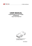
Connection and Setup Connecting multiple power supplies in parallel or in series can increase the overall current output or voltage output respectively. For this configuration to function properly, there are several items that must be set up first. Follow the instructions in this section carefully for setup. Connection Determine the total number of power supplies that you want to connect in parallel or series. Disable the output of the power supplies and power OFF the power supplies. WARNING: For safety, always turn OFF the power supplies before connecting or disconnecting wires to the output terminal. For parallel connection: Connect each power supplies’ positive (+) terminals together. Do the same for the negative (‐) terminals. For series connection: Connect one power supply’s positive (+) terminal to the negative (‐) terminal of another. Do the same for all the power supplies. Then, connect all of the power supplies’ Pin 1 of the RS‐485 interface together. Do the same for Pin 5. Below illustrates the connection diagram for parallel connection. Note: Be sure to use wires that can support the amount of output current that you want to output from the power supplies. Refer to “2.2 Output Connections” for details. 35 Master/Slave Setup Only one power supply has to be configured as a Master. The rest must be configured as Slave. Up to 3 units can be configured in total. Note: Configure Slave power supplies FIRST, and configure the Master power supply LAST. For remote or front panel operation, only control the Master power supply. Master/Slave Configuration After physically connecting the power supplies for parallel or series operation, power ON the power supplies and follow the steps below to configure a power supply as a master or slave. 1. From the CONFIG menu, select Online and press enter.The following will display: 2. While Parallel or Series is flashing, use keys to toggle between the two options. Set to Parallel for parallel connection and Series for series connection. 3. Press the key to select Slave or Master. Use the keys to select between the two options. Select Master to set the power supply as a master, or select Slave to set the power supply as a slave. Always set the Slave supplies first and Master supply last. 4.Press the key to select Addr…. Press Enter button and the display will prompt to enter an address. 36 Use the numeric keypad to enter an Address, which must be different than all other power supplies that you want to connect together in parallel. Enter any number between 0 – 31. Press Enter button to save the changes. 6. Exit the menu by pressing Esc button several times. Chapter6 Remote Control IT6512 has four standard communication interfaces:RS232,USB,GPIB,RS485.The customer can choose any one according to his demands. 6.1 RS232 interface Using a cable with two COM ports to connect power supply and PC.Then please press (Menu) button to enter the menu to configure the communication parameters.You could do the + secondary development with all SCPI commands. Note:The setup about RS232 in the program should agree with the configuration in the system set.If you want to change the communication parameters,please press the system set. + (Menu) button to enter RS-232 Data style RS232 is a 10-bit data with start bit and stop bit.The start bit and stop bit can not be edited.While you could select the odd parity or even parity under the system set. Odd or EVEN options have been saved in the nonvolatile memory. Baudrate Edit baudrate:press + (Menu) to enter the menu setup,you could select the baudrate among the following options: 4800 9600 19200 38400 57600 115200 37 RS-232 connection Please use a straight-through RS232 cable with DB-9 interface and connect the RS232 serial port with the controller’s serial port(for example.PC). Form 2-2 give a detailed description for each pin. RS-232 pins description Pin description 1 connectionless 2 TXD,transmit data 3 RXD,receive data 4 connectionless 5 GND 6 connectionless 7 connectionless 8 connectionless 9 connectionless RS-232 Troubleshooting: If you meet some problems when communicating with PC by RS232 interface,please check the following items: Please check the parameters setting PC and power supply must have the same configuration in the following items: baudrate, parity bit,data bit and flow control.Please note that power supply has been configured with a start bit and stop bit(the two values are fixed). Check the cable Ensure you have used the correct communication cable.Please pay attention that some cable may not have a correct internal wiring even it is with a appropriate DB9 interface. The RS232 communication cable should have been connected to a correct serial port of the PC. Communication Setup Please ensure the PC and power supply have the same configuration in the following items. baudrate:9600(4800、9600、19200、38400、57600、115200).You could enter the system menu to set the baudrate. Data bit:8 Stop bit:1 Parity bit: (none,even,odd) EVEN 8 data bits have even parity ODD 8 data bits have odd parity NONE 8 data bits have no parity Native machine address: (0 ~31,factory default is 0) Parity=None Start Bit 8 Data Bits 38 Stop Bit 6.2 USB interface Use a cable with two USB ports to connect power supply and PC.You can program through USB interface to achieve all functions of power supply. The functions of USB488 interface are as follows: Interface is 488.2 USB488 interface Receive the following request: REN_CONTROL, GO_TO_LOCAL, and LOCAL_LOCKOUT When the interface receives MsgID = TRIGGER USBTMC command,it will transmit the TRIGGER command to the function layer The functions of power supply’s USB488 are as follows: receive all SCPI commands device is SR1 enabled device is RL1 enabled device is DT1 enabled 6.3 GPIB Interface Use a IEEE488 bus to connect GPIB interfaces of power supply and PC.Please ensure that the + (Menu) to screws have been screwed down in order to have a full connection.Then press enter the system menu to set the address.The address range of power supply is 0-31.After you set the address,please press button to confirm.GPIB address is saved in nonvolatile memory. 6.4 RS485 Interface Use a straight-through cable with two RS485 ports to connect power supply and PC. Press + (Menu) button to enter the system set.Please set the following parmeters:baudrate,data bit,stop bit,parity bit,native machine address.The setting way is the same with RS232 setting. The definition for each pins of RS485: 1. Pin1 is B line of RS485 interfacE 2. Pin5 is B line of RS485 interface 3. The other pins are suspended 39 Support process If you have a problem , follow these steps: 1 Check the documentation that come with the product 2 Visit the ITECH online service Web site is www.itechate.com ,ITECH is avaliable to all ITECH customers. It is the fastest source for up-to-date product information and expert assistance and includes the following features : Fast access to email AE Software and driver updates for the product Call ITECH support line 4006-025-000 40