1
RN Commands Version 4.71,
8/21/2008
Page 1 of 27
User Guide
For:
™
®
Roving Networks Bluetooth
Serial Module Command Set
As applied to
RN-21/22/24, and RN-41
Bluetooth Modules,
BluePort-XP, RN-USB-X, and FireFly Serial Adapters
Version 4.71
August 21, 2008
Roving Networks, Inc.
Subject matter contained herein is proprietary to Roving Networks Incorporated, and all manufacturing, reproduction,
use and sale rights pertaining to such subject matter are expressly reserved. The recipient, by accepting this material, agrees
that this material will not be used, copied or reproduced in whole or in part except in conjunction with the design,
development, and support of Roving Networks hardware and firmware products. Roving Networks, Incorporated, proprietary
information is subject to change without notice.
809 University Avenue
• Los Gatos, CA 95032 • 1-(408) 395-6539 • [email protected]
www.rovingnetworks.com
RN Commands Version 4.71,
8/21/2008
Page 2 of 27
1
INTRODUCTION .......................................................................................................................................3
2
MODES OF OPERATION ..........................................................................................................................5
3
CONFIGURATION ....................................................................................................................................6
3.1 Configuration Locally over Serial port………………..….……………………………………6
3.2 Configuration Remotely over Bluetooth……………………………………………………….6
3.3 Using PIO/Dip switches for quick configuration………...……………………………………7
4
COMMAND SET REFERENCE .................................................................................................................8
4.1.1 Using Low Power modes (inquiry and page timers)….……………………………………14
4.1.2 Using Low Power SNIFF mode……………………………………………………………14
4.1.3 Enabling Deep Sleep………….……………………………………………………………14
4.1.4 Disabling Output Drivers………...…………………………………………………………15
4.1.5 Lowering Transmit Power (see appendix B)………………………………………………15
4.2 Profile Selection………………………………………………………………………………16
4.3 Using PIO Pins to create Modem control signals………….…………………………………16
5
COMMAND QUICK REFERNCE TABLE.................................................................................................. 17
6
FACTORY DEFAULT SETTINGS ............................................................................................................ 19
7
DESIGN CONCERNS .............................................................................................................................. 20
7.1 Hardware Signals and Power………………………………………………………………20
7.2 Latency vs. throughput and packetization ….……..………………………………………21
7.3 Limitations of 7 bit mode..…………………………………………………………………21
8
COMMON PROBLEMS AND QUESTIONS: ............................................................................................. 22
9
DISCOVERY AND CONNECTION ........................................................................................................... 23
9.1 Example of a Master Discovery and Connection Sequence ………………………………23
9.2 Using PIOs/Switches for Auto-pairing and Auto Connection .……………………………23
10 INSTANT CABLE REPLACEMENT EXAMPLE ........................................................................................ 24
11 FIREFLY CONFIGURATION SWITCHES ................................................................................................ 25
APPENDIX A - FIREFLY EVALUATION BOARD CONNECTORS, SIGNALS .................................................. 26
APPENDIX B – LOWERING TRANSMIT POWER ...........................................................................................27
809 University Avenue
• Los Gatos, CA 95032 • 1-(408) 395-6539 • [email protected]
www.rovingnetworks.com
RN Commands Version 4.71,
1
8/21/2008
Page 3 of 27
Introduction
Scope: This Command Set document along with the RN-21/41 (class 1), RN22/24 (class 2),
and the FireFly™ evaluation board are created to enable developers and integrators an
opportunity to create wireless networks using Bluetooth technology. The goal is to make the
transition to Bluetooth wireless networks as seamless and easy as possible. This document will
explain how to establish Bluetooth communications between Bluetooth enabled devices for
data applications .
Background: The FireFly evaluation board is designed to accommodate the Class1 Bluetooth
radio modem serial modules with 2.4GHz RF ceramic chip antenna or external SMA antenna
Jack.
The RN-21, RN-22, and RN-41 modules are Bluetooth ver. 2.0 compliant. The
evaluation board enables a stable platform environment to test serial RS-232 cable
replacement over Bluetooth RF links before going directly to an embedded printed circuit board
design and layout.
Commands: This document describes the protocol used to control and configure RN-XX
Bluetooth Serial Modules. The protocol is similar to the industry standard Hayes AT protocol
used in telephone modems due to the fact that both types of devices are connection oriented.
Appropriate commands have been provided to make the module perform the two core actions
of a Bluetooth device, which is make/break connections and Inquiry. Additional commands are
also provided to perform other functions. The RN-XX serial radio modems can be configured,
commanded, and controlled through simple ASCII strings through the hardware serial UART or
over a remote Bluetooth RF connection .
Applications: The FireFly and RN-24 evaluation boards can be used for both embedded and
PC product applications. The FireFly has RS-232, DB-9 and 0-3.3Vdc direct UART interfaces
to the module. RN-24 has thru hole pins on pin-strip headers, 12 General Purpose 3.3Volt
input/output pins (PIO’s) available for use. Both modules have the ability to control power to the
module, and reset to factory defaults.
Pico-Nets: For applications that require more than point-to-point (2) devices communicating
simultaneously – this is called a pico-net. These applications require one of the Bluetooth
devices to manage all the network connections. The easiest implementation is using a
Personal Computer (PC) that manages this activity with MS Windows Bluetooth stack software
and USB Bluetooth Communicator plugged into the PC (see figure below).
809 University Avenue
• Los Gatos, CA 95032 • 1-(408) 395-6539 • [email protected]
www.rovingnetworks.com
RN Commands Version 4.71,
8/21/2008
Page 4 of 27
RN-24 module
RN-41 Module
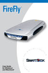
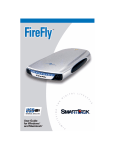
FireFly Adapter
RN-USB-X USB dongle
Making a Connection
FireFly shows up under Service discovery defaulted as Serial Port Profile (SPP) Service “SPP
on FireFly-5302”, where SPP is the service name and RN-5302 is the local device name. The
local device name can be changed, and defaults from the factory to the last 2 bytes of the
Bluetooth address.
To connect to FireFly, browse for services, you should see: “SPP” as the Profile. FireFly and
will be connected to a Virtual COM port on PCs, Palm Pilot’s, PocketPCs, or other clients.
Once connected, data will flow in both directions in regular data mode as if the serial port were
locally attached. Commands to the device can be sent by a remote RF Bluetooth device or on
the local UART hardware connection (if not connected over Bluetooth) by typing “$$$” (three
dollar signs) FireFly is a Class1 Bluetooth device with high power transceiver (100meters/330
feet) actual range may vary due to environment or type of client device used to connect to
FireFly.
NOTE: Only one client can make connection to FireFly slave at a time, and there is a limit of 7 simultaneous
communicating devices in a Bluetooth pico-net network. As a master, it is possible to make multiple connections
from FireFly, but only in a point-to-point, serialized mode. At this time Roving Networks firmware does not
support multipoint master mode.
809 University Avenue
• Los Gatos, CA 95032 • 1-(408) 395-6539 • [email protected]
www.rovingnetworks.com
RN Commands Version 4.71,
8/21/2008
Page 5 of 27
2. Modes of Operation
0- Slave mode – This is the default mode, whereby other Bluetooth devices can discover and
connect to the device. Outbound connections can also be made in this mode.
1- Master Mode - This mode is useful when the device only wants to initiate connections (not
receive them). In this mode the device will NOT be discoverable or connectable.
2- Trigger Master Mode - In this mode, the device will automatically connect to the pre
configured remote slave address when a character (or characters( are received on the local
UART. Connection will continue until a configurable idle timer (1 to 255 seconds) determines
that no more data is being received, or a configurable BREAK character is seen.
3-Auto-connect Master Mode - This mode can be set by command, or by sensing of Switch 3
during powerup on the FireFly.(PIO6 high on the module). If this mode is set, the device will
initiate a connection to the pre-stored remote address immediately upon power up. If no
address is stored, an inquiry process will be attempted and the first device found that matches
the COD will be stored. In this mode, data is passed without being interpreted by the Blueport
(high speed), hence the connection cannot be broken via command. If disconnect occurs, the
device will attempt to re-connect until successful.
4-Auto-connect DTR Mode - This mode must be set by command. This mode operates like
mode 3 Auto-Connect, except that the connection and disconnection are controlled by Switch 3
on the FireFly.(PIO6 on the module). Setting the Switch ON/PIO6 high will initiate autoconnect process, a nd OFF/PIO6 low will cause a disconnect.
5-Auto-connect ANY Mode - This mode must be set by command. This mode operates like
mode 4 DTR mode, except that each time the Switch/PIO is set, an inquiry is performed and
the first device found is connected. The stored address is NOT used, and the found address is
never stored.
809 University Avenue
• Los Gatos, CA 95032 • 1-(408) 395-6539 • [email protected]
www.rovingnetworks.com
RN Commands Version 4.71,
8/21/2008
Page 6 of 27
3. Configuration
Command Mode (vs Normal Data mode)- Upon powerup, the device will be in data mode.
To enter
command mode, The characters “$$$” must be sent. The device will respond with “CMD”. To exit
command mode, send “---<cr>”. The device will respond with “END”.
Parameters, such as the Bluetooth Name, Class of Device and Serial Port settings can be viewed and
configured. This can be done locally through the serial port UART or from a remote Bluetooth RF link.
To access configuration, the device must be in command mode by issuing ($$$). While in command
mode, the device will accept ASCII bytes as commands.
3.1 LOCAL CONFIGURATION (via serial port)
Use a normal RS-232 pass through cable from PC passing ASCII characters through the terminal to the
FireFly. The communications settings should match the settings used when FireFly connects, for
example: the default is 115,200bps, 8 bits, No Parity, 1 stop bit, and hardware flow control enabled.
Local configuration works at any time when the device does NOT have a Bluetooth connection, and also
works under certain conditions when the device is connected (see the table below). If the device is in
configuration mode and a connection occurs, the device will exit configuration mode, and data will pass
back and forth from the remote device.
Run your favorite terminal emulator, HyperTerminal or other program. Type “$$$” on your screen. You
should see “CMD” returned to you. This will verify that your cable and comm. settings are correct. Valid
commands will return an “AOK”, response, and invalid ones will return “ERR “. Commands that are not
recognized will return a “?”.
To exit command mode, type “---“<cr>. (three minus signs).
NOTE1 : You can enter command mode locally over the serial port at any time when not connected.
Once a connection is made, you can only enter command mode if the config timer has not expired.
To enable continuous configuration, set the config timer to 255. Also, if the device is in Auto Master
mode 3, you will NOT be able to enter command mode when connected over Bluetooth.
3.2 REMOTE CONFIGURATION (via Bluetooth)
It is often useful to be able to perform configuration remotely over a Bluetooth connection. To do this,
connect to the device over Bluetooth, and using your terminal emulator, perform the same steps as you
would for local configuration above. When finished configuring, be sure to either reset the device, or
Send the “---“command, which will exit configuration mode and allow data to pass normally.
NOTE 2: You can only enter command mode remotely over Bluetooth if you have made a connection
and sent the $$$ within the “config timer” window after powerup. This can be modified, the default
config timer expires 60 seconds after powerup. Once the timer has expired, any data sent to the device
will pass unmodified and unrecognized by the command interpreter. The timer can be set to any value
from 0 (disable remote configuration) to 255 decimal , which allows continuous (no timeout)
809 University Avenue
• Los Gatos, CA 95032 • 1-(408) 395-6539 • [email protected]
www.rovingnetworks.com
RN Commands Version 4.71,
8/21/2008
Page 7 of 27
configuration. WARNING: Configuration (local or remote) is NEVER enabled when the device is in
auto-mode and is connected over Bluetooth.
CONFIG TIMER settings
VALUE
(decimal)
0
1-252
253
254
255
DESCRIPTION
No remote config, No local config when connected
Time in seconds from powerup to allow config
Continous config LOCAL only
Contiuous config, REMOTE only
Continous config, both LOCAL and REMOTE
3.3 Using the PIO pins/DIP switches to perform quick configuration
Function
DIP Switch
(adapters)
Factory Reset
1
Auto Discovery/Pairing
2
Auto-Connect
3
Baudrate
4
PIO (modules) Settings
PIO
PIO
PIO
PIO
4
3
6
7
OFF (0V) = disabled, ON (3V) = ARMED
OFF(0V) = disabled, ON(3V) = enabled
OFF(0V) = disabled, ON(3V) = enabled
OFF(0V) = stored setting (115K), ON(3V) = 9600
Factory Reset- Set this switch/PIO on powerup. This arms the reset function. Then toggle the
switch/PIO 3 times and all settings in the device (other than the Bluetooth name) will return to defaults.
Auto Discovery/Pairing Mode - Used with Switch3/PIO6. If Switch3/PIO6 also set,, the device will
perform a device Inquiry Scan, searching for a partner Device with a special matching class, (0x55AA)
and once found, store the address of such device into the remote address field, and then auto-connect
to the remote device. If Switch3/PIO6 is NOT set, the device will enter slave mode with the special
matching class, waiting to be found by the master. This mode is usually set once on both ends of a pair
of devices, for instant “cable replacement”, and then removed.
Auto Connect mode –This is equivalent to auto-master mode 3 in software. The device will connect to
the stored address.
If Switch2/PIO3 is also set, new discovery/pairing can be made, see above.
Baud Rate select - used to configure 9600 or software selected (default=115K ) baudrate. If the switch
is OFF, the stored baudrate setting will be used. When the switch is in the ON position, the baudrate will
be set to 9600 regardless of the software setting.
NOTE: for the purpose of configuration above, the swithes/IO pins are sampled ONLY at power up
time, (during the first 500milliseconds) so they can be used for other functions once the device is in
operation. The exception is the factory reset switch/PIO, which once enabled, can be toggled at any
time after powerup, a total of 3 transitions will cause the factory reset to occur.
809 University Avenue
• Los Gatos, CA 95032 • 1-(408) 395-6539 • [email protected]
www.rovingnetworks.com
RN Commands Version 4.71,
8/21/2008
Page 8 of 27
4. Command Reference
The commands are all single or 2 character, generally comma delimited. Commands and hex input data can be
upper or lower case. Text data, such as Bluetooth name, and pin code, are case sensitive. Commands fall into 4
general categories:
SET COMMANDS - store information permanently and take effect after power cycle or software reset.
GET COMMANDS -retrieve the permanently stored information for display to the user.
CHANGE COMMANDS –temporarily change the value of serial baudrate, parity, etc.
ACTION COMMANDS – perform action such as inquiry, connect, etc.
SET COMMANDS
S7,<1,0>
- 7 bit data mode. 1 to enable, 0 to disable. (setting can be seen with the “d” command).
SA,<1,0>
- Authentication. 1 to enable, 0 to disable . This will force authentication when any
remote device attempts to connect. Regardless of this setting, if a remote device forces
authentication, this device will respond with the stored pin code. Once a remote device
has exchanged pin codes with this device, a link key will be stored for future use. Up to 8
keys are automatically and permanently in flash on the device, in a first in, first out
fashion.
SB,<timer>
- Send BREAK. This is an immediate command, which can send a BREAK signal on the
TX . The timer is used to send a variable length BREAK signal.
Timer value
Break length (in milliseconds)
1= 37ms, 2=18.5ms, 3=12ms, 4=9ms, 5= 7ms, 6=6ms.
Example : “SB,2” sends a 18.5 millisecond break signal.
SC,<hex word>
- Service Class ( 16 bits, 11 used, this is used with Device Class below to create the 24
bit class of device number.
Example : “SC,0002”
SD,<hex word>
- Device Class (major and minor in a 16bit word, used with service class above)
Example : “SD,8040”
SE,<1,0>
- Encryption 1 to enable, 0 to disable.
SF,1
- Set Factory Defaults.
SI, <hex word> -
- Inquiry Scan Window. Sets amount of time device spends enabling inquiry scan
(discoverability) . Minimum value is 0x0012, corresponding to about 1% duty cycle.
Inquiry interval is fixed at 0x800, so time spent in inquiry is 0x12/0x100 by default.
Maximum value is 0x800, set to 0x0000 to disable inquiry scan and make device nondiscoverable. Default value is 0x0200.
809 University Avenue
• Los Gatos, CA 95032 • 1-(408) 395-6539 • [email protected]
www.rovingnetworks.com
RN Commands Version 4.71,
8/21/2008
Page 9 of 27
SJ, <hex word> -
- Page Scan Window. Sets amount of time device spends enabling page scan
(connectability) . Minimum value is 0x0012, corresponding to about 1% duty cycle.
Page Scan interval is fixed at 0x800, so time spent in page scan mode is 0x12/0x800 by
default. Maximum value is 0x800, set to 0x0000 to disable page scan and make device
non-connectable. Default value is 0x0200.
SL,<E,O,N>
- Parity.
Can be any of, Even, Odd, or None. Only the first character is needed
Example : “SL,E”
SM,<3,2,1,0>
sets the parity to Even.
- Mode (0=slave, 1=master,2=trigger, 3=auto, 4=DTR, 5=ANY)
Example : “SM,1”
SN,<name>
sets the mode to Master
- Friendly Name of the device, 20 characters maximum.
Example : “SN,MyDevice”
S-,<name>
- Serialized Friendly Name of the device, 15 characters maximum.
This command will automatically append the last 2 bytes of the BT MAC address to the
name. Useful for generating custom names, but still having unique serialization.
Example : “S-,MyDevice” will set the name to “MyDevice-ABCD”
SO,<text>
- Extended Status String, 8 character maximum. Setting this string to from 1 to 8
characters will enable status messages to be sent to the local serial port. Two status
messages are sent, when a Bluetooth connection is established, the string
”<text>CONNECT” will be sent. Upon a Disconnect, the string <text>DISCONNECT
will be sent. This parameter is useful, for example, when connected to a printer, the
printer can examine an escape sequence, if the <text> is set to ESC%, the printer can parse
the ESC%CONNECT and ESC%DISCONNECT messages without interfering with
normal print jobs. In Trigger or Master modes, the first character of this string is used as
the BREAK connection character.
Example : “SO,ESC%”
SP,<text>
- Security Pin Code, 20 character maximum
Example : “SP,secretcode”
SR,<adr>
- Remote Address. 12 hex digits, (6 bytes) no spaces or chars between.
Example : “SR,00A053112233”
NOTE: 2 special characters can be used here:
“SR,Z” will erase any stored address.
“SR,I” will write the last address seen by using the Inquiry command.
This can be helpful when you just have 1 other device in range and want to
quickly store and connect to it.
809 University Avenue
• Los Gatos, CA 95032 • 1-(408) 395-6539 • [email protected]
www.rovingnetworks.com
RN Commands Version 4.71,
SS,<text>
8/21/2008
Page 10 of 27
- Service Name (1 to 20 characters ).
Example : “SS,SerialPort”
ST,<num>
- Config Timer, # of seconds ( range= 0 to 255 decimal,, default = 60 decimal) to allow
remote configuration over Bluetooth after power up in Slave Mode. In all Master
modes, the remote config timer is set to 0 (no remote configuration). In Trigger Master
Mode, this Timer is used as an Idle timer to Break the connection after the timer expires
with no characters being received.
Example : “ST,0”
Example : “ST,255”
SU,<rate>
- Baudrate, {1200, 2400, 4800, 9600, 19.2, 28.8, 38.4, 57.6, 115K, 230K, 460K, 921K },
only the first 2 characters are needed.
Example : “SU,57”
SW,<hex word>
disables remote configuration
enables remote configuration forever
sets the baudrate to 57600 baud.
- Enable low power SNIFF mode. Default is 0000=disabled. SNIFF mode allows
extreme low power operation. Device goes into a deep sleep, and wakes up every
every 625us * <hex word> to send/receive chars.
Example: “SW,0050”
enables Sniff mode and sets the interval time to 50 hex * .625 = 50 milliseconds.
This will cause the module to enter low power sleep, and wake once every 50 milliseconds
to check for RF activity. See Section 4.1 for more details on Sniff.
SX,<1,0>
- Bonding enabled, creates a single stored connection pair with a remote device.
SZ,<num>
- Raw Baudrate (decimal) allows entering of non-standard baudrates. Based on the
formula num = Baudrate * 0.004096.
S~,<0,1>
- Profile to use. 0=SPP (default), 1 = DUN DCE, 2 = DUN DTE, 3 = MDM.
See Section 4.2 for more details on Profiles.
S?,<0,1>
- Role Switch. Enables and disables Role Switch. If set, when an incoming connection is
occurs to a slave mode device, an attempt will be made to force a role switch, allowing
the slave to become the master. This is useful in situations where high speed data is being
sent from the local device up to the remote host, and can result in better performance.
However this may create a situation whereby the connecting host will not be able to make
additional outbound connections (multipoint) while connected to this device. Default is
DISABLED.
S$,<char>
- Configuration detect character. This allows a change from the default $$$ to some other
character. Factory defaults returns the device to $$$.
809 University Avenue
• Los Gatos, CA 95032 • 1-(408) 395-6539 • [email protected]
www.rovingnetworks.com
RN Commands Version 4.71,
8/21/2008
Page 11 of 27
GET COMMANDS
D
Display basic settings. Address, Name, Uart Settings, Security, Pin code, Bonding,
Remote Address. This command is an easy way to check the configuration.
E
display extended settings. Service Name, Service Class, Device Class, Config Timer.
M
display remote side modem signal status.
O
display other settings. Config character, IOport values, debug mode.
G<X>
display stored settings . These commands correspond to the SET commands above.
Example : “GS”
will return 1 or 0 depending on the value of security.
In addition to the above, there are a few other useful commands available .
GB
GK
G&
V
returns the Bluetooth Address of the device.
returns the current connection status: 1=connected, 0 = not connected.
return a hex byte containing the value of the PIO Pins
return the software release version
CHANGE COMMANDS
U,<rate>,<E,O,N> -
Temporary Uart Change, will change the serial parameters immediately, but not
store them. Command will return “AOK” at current settings, then automatic ally exit
command mode, and switch to new baudrate.
Baudrate must be EXACTLY 4 characters = {1200, 2400, 4800, 9600, 19.2, 38.4, 57.6,
115K, 230K, 460K, 921K }. Parity is E, O, or N (must be capitals).
Example : “U,9600,E”
Sets baudrate to 9600, parity even.
ACTION COMMANDS
$$$
- enter command mode Characters are PASSED until this exact sequence is seen. If any bytes
are seen before these chars, or after these chars, in a 1 second window, command mode will not
be entered and these bytes will be passed on to other side.
NOTE: this char is configurable, use the S$,<char> command to change the char.
---
- exit command mode. Exit command mode. “END” will be displayed. If connected
over BT, data will now pass in both directions.
C{,<address>}- connect The device will attempt to connect to the remote stored BT address, or an optional
address can be entered directly.
CT<address>,<timer ( 1/4secs) > - connect with TIMER. The device will NOT use or store the remote address,
rather will make a connection to the <address> (REQUIRED). The device will automatically
809 University Avenue
• Los Gatos, CA 95032 • 1-(408) 395-6539 • [email protected]
www.rovingnetworks.com
RN Commands Version 4.71,
8/21/2008
Page 12 of 27
disconnect after 7 seconds if no data is seen from UART or BT. An optional timer value can be
entered to change the default 7 seconds. This value is in ¼ seconds. So for a 30 second timer,
use 120 as the value. The maximum value is 255, or 64 seconds.
F,1
Go to FAST data mode, ends configuration immediately.
I<,time>,<cod> performs an inquiry scan. Default time is 10 seconds, maximum is 48. Cod
is optional class of device, 0 or no entry looks for all device classes. A maximum of 9 devices
will be returned. As devices are found, they are displayed in the format below:
<bt address> , <bt name> ,<cod>
00A053000123,MySerialPort,72010C
IN<time>,<cod> performs an inquiry scan, does not return the Bluetooth NAME ( returns much
faster, since name requires a remote lookup for each device found).
IS<time>
performs an inquiry scan, with a COD of 0x001F00, which is the default COD for
Roving Networks Serial adapters and modules.
IR<time>
performs an inquiry scan, with a COD of 0x0055AA, which is the special COD used
By Roving Networks Serial adapters and modules to enable “instant cable replacement”.
H
help, will print out a list of commands and their basic syntax
K,
Kill (disconnect) from the current connection.
P,<char>
Pass thru, sends any chars along up to a CR or LF while in command mode.
Q
Causes device to be non-discoverable and non-connectable (temporarily). Does not survive a
power cycle or reset. Used with the Z command below. Use the “W” command to re -enable.
This command will return “Quiet” as a response.
R,1
forces a complete reboot of the device (similar to a power cycle).
T,<0,1>
Pass receive data (from uart or BT) while in command mode. Returns (T=0 , T=1 based on input).
W
Re-enables discovery and connection. This command reloads the stored value of the Inquiry
and Page Windows to re-enable. For example, to turn off Discovery but still allow connections,
send an “SI,0000” command, and follow it with “W” command. This command returns “Wake”
as a response.
&
returns the value of the switches on BluePort, or value of PIO3,4,6,7 on other modules.
Z
Enters low power deep sleep mode (<2ma) when NOT connected. Can only be exited by toggling
the RESET pin on the module (causing a HARD reset) , or power cycling the device. To get the
lowest power mode, first issue a Q, then a Z. Use the SNIFF settings to get lowest power while
connected.
809 University Avenue
• Los Gatos, CA 95032 • 1-(408) 395-6539 • [email protected]
www.rovingnetworks.com
RN Commands Version 4.71,
8/21/2008
Page 13 of 27
COMMANDS to MANIPULATE GPIO
CMD
@
&
%
^
*
VALUE
<hexword>
<hexword>
<hexword>
<hexword>
<hexword>
DESCRIPTION
Set direction bits for GPIO
Set values for GPIO
Store powerup direction bits for GPIO
Store powerup values for GPIO
Set values for PIO8,9,10,11
The GPIO command interface uses combination
of 2bytes, a mask, and value, packed into a hex
word for each command. The first byte, the
mask, determines which GPIO are to be
affected, and the second byte is the value to set.
15 --------- 8 7 -------- 0
<hexword> = MASK[7...0] VALUE[7..0]
There are 2 registers used to control the GPIO, the first is a direction register. This controls whether the GPIO is an input or
an output. The second register is the value to apply to the GPIO if set to an output, or is the value of the built-in weak pull-up
resistor if the GPIO is set to an input. These settings are immediate, and do not survive a power cycle.
Examples: S@,8080
S&,8080
S&,8000
sets GPIO-7 to an output
drives GPIO-7 high
drives GPIO-7 low
Power-up values: These 2 registers will apply the direction and values upon each subsequent power-up:
Examples: S%,0101 sets GPIO-0 to an output on power-up
S^,0303
drives GPIO-0 high, and pulls up GPIO-1.
Multiple bits can be set, any bits with a mask of 0 are left unaffected for the command.
Some GPIO are checked at power-up time to perform certain functions, so care must be taken when manipulating them.
GPIO3, 6, are used to automatically set master mode, and auto discovery. If it is desired to use these GPIO for other purposes
at power-up, a special command must be used to disable their being sensed at power-up time. This command is “SQ,4<cr>”
this will set a flag in a stored register that is read at power-up. The Power-up settings for the GPIO can also be viewed using
the “O” (other settings) command.
WARNING:
GPIO-4 is used by the system to reset stored parameters to factory defaults. If GPIO4 is pulled high on power-up, and then
toggled 3 times, all user settings will return to default values. Therefore this pin should not be used as an output, and should
not be driven high at power-up time (first 1 second of operation).
NOTE:
GPIO2 and 5 are driven by the embedded software as outputs, they can be disabled using the direction command, (to save
power, for example) and used as inputs. If set to outputs the software will override any user values.
SETTING GPIO 8-9-10-11
S*,<hexword> = MASK[11..8] VALUE[11..8]
For the upper 4 GPIO, a single word controls the mask and values, and only the lower 4 bits of each byte are used. The first
time this command is used, all 4 GPIO are driven as outputs and remain so until a power cycle. There is no powerup
command for these bits, only the interactive one. Some modules do not offer these GPIO.
Examples:
S*,0101
S*,0100
S*,0202
GPIO-8 driven HIGH.
GPIO-8 driven LOW.
GPIO-9 driven HIGH.
809 University Avenue
• Los Gatos, CA 95032 • 1-(408) 395-6539 • [email protected]
www.rovingnetworks.com
RN Commands Version 4.71,
8/21/2008
Page 14 of 27
4. 1 Using Low Power Modes
4.1.1 Inquiry(Discovery) and Page(Connection) Windows
There are 2 timers that can be used to lower the idle Slave mode power of the radio. When not connected, the
Radio is active for a percentage of time listening to see if any other device wants to Discovery (inquire) or
Connect (page). The amount of time the radio is on is called the window, and the rate at which the process cycles
is called the interval. The interval is fixed at 0x800 (1.28seconds) with Sniff disabled, and 2.56 seconds with Sniff
enabled. The window can be adjusted. The default window is 0x200 (320 ms) or 25% duty cycle.
By lowering the window value , power can be saved at the expense of possibly missing an inquiry or page. Since
the host usually retries automatically many times, the only downside is a delay in discovery or connection time.
The minimum window for inquiry or page is 0x0012 (11.25ms). corresponding to about a 1% duty cycle.
Thus, average power can be reduced from >20ma to <5ma in standard mode, and <3ma in Sniff mode.
It is also possible (and desirable for security reasons) to completely disable inquiry. Once a host has found and
installed a device, inquiry is not needed, only page is used to make a connection.
To disable inquir y and still allow connections, set the Inquiry timer to 0 with “SI,0000”.
4.1.2 SNIFF mode
Sniff mode is another power conservation method utilized by Bluetooth. By default, Sniff mode is disabled, and
the radio is active continuously when connected (about 25-30ma) . In Sniff mode, the radio wakes up at specific
intervals, and sleeps in very low power mode (around 2ma) otherwise. The power savings can be quite dramatic.
To enable it, use the “SW,<hex word>“ command.
Example interval timers:
0x0020 = 20ms. (32 decimal * .625 = 20).
0x0050 = 50ms, 0x00A0 = 100ms, 0x0190 = ¼ second, 0x0320 = ½ second, 0x0640 = 1 second.
Sniff mode only pertains to an active connection. When a connection is made, both master and slave must
support Sniff mode, and agree to the Sniff window, otherwise the radio will stay in full active on mode.
Note: the maximum allowed Sniff interval is about 20 seconds = 0x7FFF sniff word setting.
4.1.3 Enabling Deep Sleep
Deep Sleep mode can be used to obtain extremely low power operation. The device totally shuts down and only
draws about 300uA of current in this mode. To enable Deep Sleep, set the high order bit of the Sniff word =
0x8000. This bit is NOT used to determine the sleep interval, it is only used as a flag to enable deep sleep. For
example, If you want ½ second sleep 0x0320, with Deep sleep, you would set the sniff word to 0x8320.
809 University Avenue
• Los Gatos, CA 95032 • 1-(408) 395-6539 • [email protected]
www.rovingnetworks.com
RN Commands Version 4.71,
8/21/2008
Page 15 of 27
In normal low power sleep (not deep sleep) the firmware is still running in idle mode, and wakes up about 20
times per second to check ports, update Leds etc. During Deep sleep, the firmware actually stops running some
tasks. For example, the LEDs only update about once per second.
There are 3 ways to wake the radio from sleep mode. The first is to send a character to the UART. Transitions on
the RX pin will wake the device from sleep. Wake time is worst case 5ms. Because of this, the first character
sent is generally lost by the radio. A better way to wake the radio is to toggle the CTS line from LOW to HIGH,
Wait 5ms, and then send data. The third way is automatic, the radio will wake every <hex word> slot times (1 slot
time = 625us) as defined above. The radio wakes and listens to see if the other side of the connection has
anything to send. This wake time is typically about 5ms (8 slots) even if no data is to be transferred.
Once the radio is awake it will stay active for exactly 1 second of inactivity, and then sleep again.
NOTE: setting this mode can cause latency issues, and dropped bytes/loss of performance in cases where large
amounts of data are being transferred. The nuances of Bluetooth Sniff can be complex, contact Roving Networks
if necessary for more details on how to utilize Sniff mode.
4.1.4 Disabling Output drivers
Use the command “ S%,1000” to set all PIO0-11 to inputs.
This will also turn off the LED (PIO5) on the FireFly adapter.
4.1.5 Lowering Transmit Power
See Appendix B. (at the end of the document).
4.2 Profile Selection
The default profile is Serial Port Profile (SPP). The firmware also supports the DUN profile in both master and
slave modes. To change the profile, use the “S~,<num>” command.
Profile:
0
1
2
3
-
Default SPP. (no modem control)
DUN DCE (slave or gateway).
DUN DTE ( master or client).
MDM SPP with modem control signals.
The most common use of DUN profile is to enable a BT client to connect to a dialup modem. For this mode, use
profile 1 (DUN DCE) via command “S~,1” . You may also want to set the Class Of Device so that clients can
recognize the device as a Bluetooth modem. The correct COD for a Bluetooth modem is 0x040210. This can be
set using the commands below:
“SC,0004”
“SD,0210”
A number of modem control signals are supported when in DUN or MDM modes and their use is described below.
809 University Avenue
• Los Gatos, CA 95032 • 1-(408) 395-6539 • [email protected]
www.rovingnetworks.com
RN Commands Version 4.71,
8/21/2008
Page 16 of 27
4.2 PIOs used as modem control signals
The Firefly and RN-XX modules have the ability to replicate the required modem control hardware signals
automatically once a connection is made. These signals are transferred outside the data channel (using
RFCOMM control channels) and are automatically updated. The default SPP profile (profile=0) does NOT drive
these signals or report back inputs. If DUN or MDM profiles are enabled (pofile =1,2, or 3), the following
signals are automatically driven and received.
Inputs: (read and sent back over Bluetooth to the remote host).
PIO3 = DCD ( switch 2)
PIO6 = DSR (switch 3)
PIO7 = CTS (switch 4)
Inputs are ACTIVE LOW.
Outputs: (sent from the remote Bluetooth host, and driven out )
PIO10 = DTR - this is ACTIVE HIGH
PIO11 = RTS - this is ACTIVE LOW.
On the Firefly, the DIP switches can also be used to set/clear the DCD, CTS, and DSR signals. DTR and RTS are
available on the 9 pin header as well.
809 University Avenue
• Los Gatos, CA 95032 • 1-(408) 395-6539 • [email protected]
www.rovingnetworks.com
RN Commands Version 4.71,
8/21/2008
Page 17 of 27
5 Command Quick Reference
SET COMMANDS
FACTORY SETTING
S7,<1,0>
- 7 bit data mode enable/disable
0= disabled
SA,<1,0>
- Authentication enable/disable
0= disabled
SB,<timer>
- Send BREAK
Not Applicable
SC,<hex word> - Service Class
0x0000= unknown
SD,<hex word> - Device Class
0x1F00= undefined
SE,<1,0>
- Encryption enable/disable
0=disabled
SF,1
- Factory Defaults
SI,<hex word> - Inquiry Scan window
0x0200
SJ,<hex word> - Page Scan window
0x0200
SL,<E,O,N>
- Parity
N=None
SM,<0,1,2,3,4,5> - Mode (0=Slave,1=mstr,2=trig, 3=auto, 4=DTR, 5=ANY)
0=Slave
SN,<text>
- Name
FireFly-xxxx
SO,<text>
- Connect/Disconnect Status String
NULL= no status string
SP,<text>
- Pin Code
1234
SR,<adr>
- Remote Address (SR,Z to remove)
NONE SET
SS,<text>
- Service Name
SPP
ST,<num>
- Config Timer
60 seconds
SU,<rate>
- Baudrate
115K
SW,<hex>
- SNIFF rate
0x0000=disabled
SX,<1,0>
- Bonding
0=disabled
S~,<0-3>
- Profile setting 0=SPP, 1=DCE, 2=DTE, 3=MDM
0 = SPP
SZ,<num>
- Raw Baudrate
S?,<0,1>
- Enable /Disable Role Switch
0=disabled
GET, DISPLAY COMMANDS
D
E
O
G<X>
H
GB
GK
G&
V
- Basic Settings
- Extended Settings
- Other Settings
- Stored setting
- Help
- BT Address
- Connection Status
- I/O Ports
- Firmware version
ACTION COMMANDS
C,<address>
- Connect, optional address, if no address, use stored remote address.
CT<address>,<t>- Connect, required address, optional disconnect timer in ¼ seconds.
F,1
- Enter Fast data mode, end configuration immediate.
I,<time>,<cod> - Device Scan Inquiry, time in seconds, optional cod = class of device filter, 0=all
IN<time>,<cod>- Device Scan Inquiry, returns NAMEs.
IS<time>
- Device Scan Inquiry, fixed cod=0x001F00 to find Roving devices.
809 University Avenue
• Los Gatos, CA 95032 • 1-(408) 395-6539 • [email protected]
www.rovingnetworks.com
RN Commands Version 4.71,
8/21/2008
Page 18 of 27
IR<time>
- Device Scan Inquiry, fixed cod =0x0055AA to find instant cable pairs.
K,
- Kill (disconnect) from current connection
Q
- Turn off Discovery and Connectability
R,1
- Reboot
T,<0,1>
- Pass receive data (from uart or BT) while in command mode.
U,<rate>,<E,O,N> - Temp Uart Change
&
- return the value of the DIP Switches
W
- Re-enable Discovery and Connectability.
Z
- Enter low power Sleep mode
809 University Avenue
• Los Gatos, CA 95032 • 1-(408) 395-6539 • [email protected]
www.rovingnetworks.com
RN Commands Version 4.71,
8/21/2008
Page 19 of 27
6 Factory Default Power up Settings
Bluetooth Service Profile = Serial Port Profile (SPP)
Device Mode = 0 (Slave)
Baud Rate = 115200bps,Parity=None, Data bits = 8 bits(fixed), Stop bits 1 (fixed).
Power Mode = Auto low power discoverable mode
Name of Device (local name) = FireFly-ABCD last 2 bytes of BT address
Service Name = SPP
Service Class=0000 (undefined service type)
Major & Minor Class Of Device (COD) = 0x1F00 (unknown device type)
Authentication Disabled
Encryption Disabled
Discovery Enabled (0x0200 = windowl, fixed interval of 0x800= 1.28 Seconds )
Connection Enabled (0x0200=window, fixed interval of 0x800 = 1.28Seconds)
Bonding Disabled
Config Timer=60 seconds
SNIFF mode disabled
Default PIN = “1234”
Note: PIO(4) Switch 1, Set ON at powe r up time, and then toggled 3 times will change all
settings above back to their factory values. (except the Device name). Device will reboot
immediately upon detection of this mode.
809 University Avenue
• Los Gatos, CA 95032 • 1-(408) 395-6539 • [email protected]
www.rovingnetworks.com
RN Commands Version 4.71,
8/21/2008
Page 20 of 27
7 Design Concerns
7.1 Hardware signals and Power
1. RESET circuit. RN-41 contains a 1k pullup to VCC, the polarity of reset on the RN41 is
ACTIVE LOW. RN21/22 contain a 1k pulldown, and the reset polarity is ACTIVE HIGH.
A power on reset circuit with delay is OPTIONAL on the reset pin of the module. It should only
be required if the input power supply has a very slow ramp, or tends to bounce or have
instability on power up. Often a microcontroller or embedded CPU IO is available to generate
reset once power is stable. If not, there are many low cost power supervisor chips available,
such as MCP810T, MCP102/121, and Torex XC61F.
2. Factory reset PIO4. It is a good idea to connect this pin to a switch, or jumper, or resistor,
so it can be accessed. This pin can be used to reset the module to FACTORY DEFAULTS
and is often critical in situations where the module has been mis-configured.
3. CONNECTION status. PIO5 is available to drive an LED, and blinks at various speeds to
indicate status. PIO2 is an output which directly reflects the connection state, it goes HIGH
when connected, and LOW otherwise.
4. Using SPI bus for flash upgrade. While not required, this bus is very useful for configuring
advanced parameters of the Bluetooth modules, and is required for upgrading the firmware on
modules. The suggested ref-design shows a 6pin header which can be implemented to gain
access to this bus. A minimum-mode version could just use the SPI signals (4pins) and pickup
ground and VCC from elsewhere on the design.
Important Notes:
Placing 3.3Vdc into the PIO’s while they are set as outputs will permanently damage the
radio modules. The failure mode is short across GND and VCC. Use a 10KO resistor in
series or a 10KO pull up resistor for input and output PIO’s respectively.
•
•
•
•
Make sure to connect a common ground when using the external TX, RX inputs on the
0 – 3.3Vdc.
For a 3 wire DB-9 interface (tx, rx, gnd only) connect/short CTS to RTS, Factory default
is hardware flow control enabled CTS and RTS connected.
When using a 5.0Vdc Input, PIO’s require a 10K ohm series resistor. PIO’s are 0-3.3Vdc
not 5 volt tolerant.
A null modem adapter is required to make a direct connection to a PC serial port.
Power Terminals for Evaluation Board
Inputs on P1 power connector can be 4.5VDC to 11.0VDC. There is internal regulation down
to 3.3VDC for all circuitry. Worst case power draw for the board is 100ma when the Bluetooth
809 University Avenue
• Los Gatos, CA 95032 • 1-(408) 395-6539 • [email protected]
www.rovingnetworks.com
RN Commands Version 4.71,
8/21/2008
Page 21 of 27
radio/modem connection is established and transmitting. Power can be as low as 1ma to 25ma
average when the Bluetooth radio/modem is not connected depending on parameter settings.
Hardware Communications Connections for Modules and Eval Board
Radio TX à RX of the application Micro Controller Unit (MCU)
Radio RX ß TX of the application Micro Controller Unit (MCU)
Radio RTS à CTS of the application Micro Controller Unit (MCU)
Radio CTS ß RTS of the application Micro Controller Unit (MCU)
LEDs
.
MODE
Configuring
Startup/Config Timer
Discoverable/Inquiring/Idle
Connected
GREEN LED blink rate
10 times per second
2 times per second
Once per second
Solid ON
The YELLOW LED blinks whendata is transferred on either the RX or TX pins of the DB9 serial
port. It is a physical monitor of the actual voltage, and is not driven by software in the module.
7.2 Latency vs. throughput and packetization
The firmware automatically must make decisions on when to forward receive data coming into
the Uart RX input out the RF link. The default mode is to optimize for throughput. In some
cases, especially with smaller close spaced incoming data packets, the data can get split, with
partial packet forwarded and other data coming later. Unfortunately, Bluetooth has algorithms
that can cause significant latency between packets ( > 10ms) at certain times. If the host
protocol expects data to come as contiguous bursts and has short timeouts, this can cause
errors. There is another method of optimization, which will force the radio to attempt to keep
small bursts of data together. This is termed optimize for latency. To enable this mode, there
is a special debug command. The command is “SQ,16”. This sets the latency bit in the
firmware. To disable this mode. Use the command “SQ,0”. The value of the register can be
read with the “GQ” command, and will read back as HEX, even though it is set as decimal.
7.3 Limitations of using 7 Bit data mode
Roving Networks firmware supports selectable 7 bit data mode, using the “S7,1” command.
Unfortunately the Bluetooth hardware does not support 7 bit data, so this function is
accomplished in the firmware application. While completely functional, the performance in 7 bit
mode is less than ideal, because software emulation is required to make this work. Hence,
there is a noticeable latency and character per second processing limit in this mode.
Therefore it is not recommended that this mode be used if the desired serial baudrate is greater
than 9600 baud.
809 University Avenue
• Los Gatos, CA 95032 • 1-(408) 395-6539 • [email protected]
www.rovingnetworks.com
RN Commands Version 4.71,
8/21/2008
Page 22 of 27
8 COMMON PROBLEMS and QUESTIONS:
My Bluetooth client can see the FireFly and its serial service, but I can’t connect: This is
most likely caused by a security setting on your client. FireFly does support authentication b y
default if the client requires it (using default pincode of “1234”,) but for ease of use, you may
want to turn security off on your client. Some clients have these setting off by default, others
have them on. To check and disable security:
From your PC desktop, click My Bluetooth Places, go to the Bluetooth Device configuration (or
Advanced Configuration) drop down menu, click on the client applications tab, Select the
Bluetooth serial port application name, and click on the properties button, if “secure
connection”, or “authentication”, or “encryption” is checked, un check it.
Changing the clients COM port: Widcomm stack, the most common stack out there allows
you to connect to FireFly using a “Virtual COM” port mapper. The software installs with a
default COM port, usually COM3, COM4, or COM5. To change this setting:
From your PC desktop, click My Bluetooth Places, go to the Bluetooth Device configuration (or
Advanced Configuration) drop down menu, click on the client applications tab, Select the
Bluetooth serial port application name, and click on the properties button, then you can change
the com port.
Connecting to more than one FireFly from the same client at the same time: Bluetooth
allows 7 devices at a time in a piconet. The Widcomm stack allows you to create multiple
instances of serial port profile and connect to multiple FireFlys at the same time. To do this:
From your PC desktop, click My Bluetooth Places, go to the Bluetooth Device configuration (or
Advanced Configuration) drop down menu, click on the client applications tab, Select the
Bluetooth serial port application name, and click on the ADD COM port button, then you can
add another Bluetooth serial port and assign it to another virtual com port (such as COM9).
809 University Avenue
• Los Gatos, CA 95032 • 1-(408) 395-6539 • [email protected]
www.rovingnetworks.com
RN Commands Version 4.71,
8/21/2008
Page 23 of 27
9 Discovery and Connection
9.1
Example of a Master Discovery/Connection Sequence
From power up and no connection:
1) Perform an Inquiry to obtain BT_Address (unless it is already known).
Sent : $$$
Reply:CMD<cr>
// Places Radio in Command Mode
Sent : I,30<cr>
// Looks forBluetooth devices
Reply:00A096112233,1F00<cr>Inquiry Done<cr
2) Store the remote address just found.
Sent : SR,00A096112233 <cr>
Reply:AOK<cr>
(or just SR,I if this was the only device found ).
3) Connect.
Sent : C <cr>
Reply:AOK<cr>
// Places Radio in Connect
Device will attempt connection to remote slave. “TRYING” will be displayed.
Reply:<text>CONNECT<cr>
// this will be displayed once connection is made, if <text>
string is defined in the stored parameters.
4) Send /Receive data.
9.2
Using PIOs/ Switches for Auto-pairing and Auto-Connection
PIO3 PIO6
Function
low
high
low
high
default slave, no special function.
slave, changes cod to 0x0055aa for auto pairing.
auto master, uses STORED address....... does not try auto pairing.
auto master, auto pairing, looks for first device with 0x55aa stores it, and connects to it.
low
low
high
high
To enable cable replacement, set PIO3 high on slave, PIO3 + PIO6 high on master.
Once paired, PIO3 = low on both devices (so re-pairing with another roving device does not occur)
( PIO3 = DIP Switch 2, PIO6 = Dip Switch 3 on Firefly and BlueportXP )
809 University Avenue
• Los Gatos, CA 95032 • 1-(408) 395-6539 • [email protected]
www.rovingnetworks.com
RN Commands Version 4.71,
8/21/2008
Page 24 of 27
10 FireFly Configuration:
FireFly Serial Jumpers
NAME
1-DCD
2-RX
3-TX
4-DTR
5-GND
6-DSR
7-RTS
8 - CTS
9 - RING
DB-9 male
NC
2-RX
3-TX
NC
5-GND
NC
7 -RTS
8 -CTS
V+
IO DIR
INß
OUTà
DTE(PC)*
|
|
DCE
3-WIRE-DTE
---
|
|
<—>
OUTà
INß
INß
|
|
DTE 3 Wire * FACTORY DEFAULT
jumper between pins 9 and 10)
PWR
ANT
---
|
X
rd
( (CTS shorted to RTS) , remove 3
1
3
5
7
9
th
, 4 jumpers and install 1
2
4
6
8
10
DTE (Like a PC) , RX=2, TX=3, RTS=7, CTS=8
PWR
ANT
DCE (like a modem) , RX=3, TX=2, RTS=8, CTS=7
PWR
ANT
809 University Avenue
• Los Gatos, CA 95032 • 1-(408) 395-6539 • [email protected]
www.rovingnetworks.com
RN Commands Version 4.71,
8/21/2008
Page 25 of 27
11 FireFly Configuration Switches
ON - OFF
BOTTOM SIDE
4- Default baud(9600/ 115k)
3- AUTO MASTER
2 - AUTO DISCOVER
1 – FACTORY DEFAULTS
1- FACTORY DEFAULTS- Set this switch ON, power up unit, and toggle the switch from ON to OFF 3 times to return the unit
to factory settings.
2-AUTO DISCOVER MODE – In Slave mode, sets a special class of device which is used by a remote Master to auto connect.
IF Switch 3 also SET, the device performs a search, stores, and connects to a remote slave which has this switch 2 set .
3- AUTO MASTER MODE- BluePort acts as master, auto-connect to a stored remote address. First set the BT address of the
device to connect to using the SR command. or, have BluePort auto discover and connect by via Switch 3 AND Switch 2.
4- DEFAULT BAUD RATE - OFF = 115K (factory setting), ON = 9600. Overridden by software configuration.
Instant Cable Replacement Example
MASTER
ON - OFF
BOTTOM SIDE
4- Default baud(9600/ 115k)
3- AUTO MASTER
2 - AUTO DISCOVER
1 – FACTORY DEFAULTS
SLAVE
ON - OFF
BOTTOM SIDE
4- Default baud(9600/ 115k)
3- AUTO MASTER
2 - AUTO DISCOVER
1 – FACTORY DEFAULTS
1. Set switches as shown above.
2. Power up both devices
3. Master finds and store slave address, and auto connects.
4. Set Switch 2 on both Master and Slave back to OFF (so that they don’t try to re-pair each time
power is cycled).
809 University Avenue
• Los Gatos, CA 95032 • 1-(408) 395-6539 • [email protected]
www.rovingnetworks.com
RN Commands Version 4.71,
8/21/2008
Page 26 of 27
Appendix A FireFly Evaluation Board Physical Ports
Signal Name
CONNECTOR PIN #
IO DIR
Board PWR
Board GND
P1
P1
1
2
Power IN (5.0 -8.0 Vdc)
<—>
RS-232 SERIAL-CN1
Pin 1 - DCD
Pin 2 - TX
Pin 3 - RX
Pin 4 - DTR
Pin 5 - GND
Pin 6 - DSR
Pin 7 - RTS
Pin 8 - CTS
Pin 9 - RING
DB9
DB9
DB9
DB9
DB9
DB9
DB9
DB9
DB9
2
3
4
5
6
7
8
9
Not used
OUT
IN
Not used
<—>
Not used
OUT? *
(active low)
IN? *
(active low)
Pwr ? IN (4.5 -11Vdc)
SERIAL 3.3V (J1)
PWR
GND
CTS
RTS
TX
RX
PIO#2
PIO#10
PIO#11
J3-1
J3-2
J3-3
J3-4
J3-5
J3-6
J3-7
J3-8
J3-9
1
2
3
4
5
6
7
8
9
Optional 5VDC in
GROUND
IN
OUT? 0 - 3.3Vdc
OUT? 0 - 3.3Vdc
IN
BT Connection (high state)
GPIO
GPIO
PIO#8
SWITCH-1
SWITCH-2
SWITCH-3
SWITCH-4
LED-DL1
LED-DL2
LED-DL3
1
2
3
4
GREEN
YELLOW
RED
Reset Default Settings
Auto Discover and Pairing
Auto Connect as Master
Def Baud Rt (115K - 9600)
Pulses for status 0-3.3Vdc
RX, TX data low to high
Software controlled
6-Pin SPI (J2)
MISO
MOSI
SPICK
SPICS
PWR
GND
J2-1
J2-2
J2-3
J2-4
J2-5
J2-6
PIO-SWITCH-LEDS
PIO#4
PIO#3
PIO#6
PIO#7
PIO#5
809 University Avenue
Modem control options
PIO2 – BT connect status
PIO10- remote DTR out
PIO11- remote RTS out
DTR output
RTS output
DCD input
DSR input
CTS input
RX char low speed mode
Reserved programming)
Reserved programming)
Reserved programming)
Reserved programming)
Optional 3.3VDC Power
Optional Ground
• Los Gatos, CA 95032 • 1-(408) 395-6539 • [email protected]
www.rovingnetworks.com
RN Commands Version 4.71,
8/21/2008
Page 27 of 27
Appendix B Lowering Transmit Power
All Roving Networks Bluetooth modules and adapters adhere to the Bluetooth (1.1, 1.2, and 2.0/2.1)
specifications for power control. Both the RN-21 and RN-41 radios are Class1 capable.
The power output of the radio is automatically controlled by the baseband. Depending on the operation
mode (inquiry scan, page scan, connected) the power is adjusted. Once a connection is made, the radios
on both sides negotiate a power setting based on the perceived signal strength (RSSI).
There is some user capability to affect this operation, in order to:
- reduce effective range for security reasons
- low emissions for agency compliance concerns.
- reduce total power utilized.
Using a command, the radio can be instructed to use a maximum value that is lower than the default.
There are 7 settings in the table.
Setting
HEX value
-24
-16
-12
-8
-4
0
4
FFE8
FFF0
FFF4
FFF8
FFFC
0001
0004
Approximate output in dBm
-20
-10
-5
0
2
6
12 (the default )
The command to use is : SY,<hex value> where hex value is the unsigned integer representation of the
setting.
If a non-zero value is stored in the variable, then upon power up, the radio will use the HIGHEST value
that is less than or equal to the stored variable.
for example, if -8 = 0dBM is desired, you would enter SY,FFF8
if 0= 6dBm is desired, you would enter SY,0001 ( you could also enter 0002, or 0003 )
Power setting will take effect after power cycle or reboot or reset pin toggle.
to check the STORED power setting, use the O command.
you will see TX Power=1 or other setting equal to the value you entered.
to check the current power setting, use the GY command.
Only the actual value will be returned. Leading zeroes will not be displayed.
NOTE: the value of GY_ may not match the value in the Ocommand due how the value is used as
described above
809 University Avenue
• Los Gatos, CA 95032 • 1-(408) 395-6539 • [email protected]
www.rovingnetworks.com