1
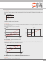
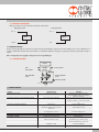
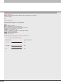
5.2.2 DIGITAL OUT CONNECTION
Utility per verificare il corretto funzionamento delle due elettrovalvole
NPN Digital OUT
PNP Digital OUT
Pin 6
Pin 4
LO AD
LO AD
0 V
+ 24 V
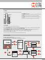
5.3 OPERATING PRINCIPLE
Using a software algorythm, the control circuit compares the input signal with the output pressure measured by the pressure sensor. When there is a
change, it activates the inlet and outlet solenoid valves to re-establish an equilibrium. This gives an output pressure that is proportional to the input
signal.
N.B.: removing the power supply, the outlet pressure doesn’t get discharged
5.3.1 FUNCTION DIAGRAM
DISPLAY
FEED
OUTPUT SIGNAL
CONTROL
CIRCUIT
INPUT SIGNAL
INLET SOLENOID
VALVE
OUTLET SOLENOID
VALVE
P
IN
PRESSURE SENSOR
OUT
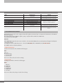
6. TROUBLESHOOTING
PROBLEM
The display does not come on
The unit does not respond or responds wrongly to the setpoint
The unit does not reach the desired pressure
The display shows an unreal value
The display is difficult to read
The unit adjusts continually
POSSIBLE CAUSES
SOLUTION
No 24V power supply
Check the power supply, make sure it is
enough and check the wiring is in accordance
with the wiring diagram
Wrong input signal configuration
Configure the appropriate type of input from the menu
Check the signal wire is connected to the right
pin
Setpoint too low
Provide a suitable setpoint
The full-scale setting is at a lower pressure
than desired
The supply pressure is too low
Wrong unit of measurement
Poor contrast
Air leak in the circuit after the unit
Continuous variation in volume Other problems
Deadband too small
Contact the manufacturer
Set the full scale correctly
Increase the supply pressure
Check the unit of measurement
Adjust the contrast
Eliminate the leak
Normal behaviour; the unit has to keep
adjusting the maintain the preset pressure
Increase the deadband
9