1
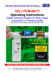
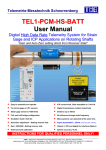
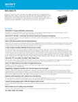
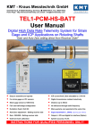
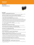
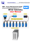
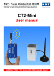
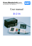
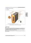
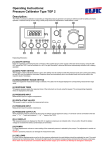
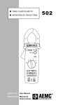
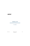
www.instrumentation.it
INSTRUMENTATION DEVICES SRL
Via Acquanera 29, 22100 COMO (Italy) tel. +39.031.525391 - fax +39.031.507984 - [email protected]
Kraus Messtechnik GmbH
Gewerbering 9, D-83624 Otterfing, +49-8024-48737, Fax. +49-8024-5532 – Germany
Web: www.kmt-gmbh.com Email: [email protected]
TEL1-PCM-BATT
Operating Instructions
Digital Telemetry System for Strain Gage
Applications on Rotating Shafts
“Gain and Auto Zero setting direct from Receiver Side!”
General Description
The TEL1-PCM single-channel telemetry system offers the easiest handling for the wireless transmission of strain gage signals
from rotating shafts. The very small encoder is available in two sizes. Housing1 = 70 x 18 x 8 mm or housing2= 35 x 18 x 12
mm. Each has a weight of 13g. The transmitter (encoder) part is simply mounted on the rotating shaft with a special fiber
reinforced tape.
The data transfer between transmitter and receiver is digital. The powering of the transmission part by the TEL1-PCM BATT is
supplied by 6-9V battery.
Functional Description
The TEL1-PCM-BATT transmitter provides a pulse code modulated signal (PCM) to an induction winding around the shaft. The
magnetic field of this winding enables the inductive transmission of the signal from coil to pickup. From there the signal is
transferred by cable (5 m) to the receiver. The maximum distance between the transmitter coil and the pickup is 150mm.
The receiver unit offers a BNC connector at the front panel with analog outputs ± 10 V and a optional a digital output for PCM
interface ECIA100 (for notebooks) or IF16 (PCI Desktop). An LED bar indicator shows the actual level and a successful Auto
Zero calibration. Overload is indicated by the last LED´s in pos. or neg. direction of the bar graph. These OVL-LED´s operate in
peak-hold mode and are reset by pressing the overload switch.
Strain gage sensors (>350 Ohm) in full- and half- bridge configuration can be directly connected to the transmitter. The
excitation is fixed to 4 Volt DC and the gain is set by the gain switch on the receiver side. An auto-zero (AZ) adjustment is
executed by pressing the AZ button on the front side of the receiver. The successful AZ operation is indicated by a yellow LED
in the middle of the LED bar indicator. The yellow LED flashes as long as the AZ is in progress. When the AZ completes the
LED continuously illuminates. A continued flashing of the yellow LED indicates some error in the AZ electronics. In this case
please contact the support of KMT. Additional to the AZ you have the possibility to calibrate the bridge by external shunt.
(+ and -). The AZ setting is stored in a Flash-RAM and thus is not lost during power-off. Use only shielded sensor cable.
TEL1-PCM-BATT Set Contains:
Inductive PH-Pickup
with 5m cable
TEL1-PCM-BATT-DEC
(Decoder)
Mounting tape
25mm and 50mm
Length 50meter
Ferrite tape
30mm x 3 meter
(isolate magnetic field
between shaft and coil)
CU wire, 0.5mm
for coil (insulated
with lacquer)
TEL1-PCM-BATT-STG
DC-Power cable
Version 2008-10
6V Lithium
battery
(Encoder for strain gages)
2
Hexagon key to
activate the OLV
and AZ switch
Screw driver to
set the gain
Technical Data are subject to change without notice!
Technical Data
Housing 1 (70 x 18 x 8 mm)
Standard housing for battery version
Housing 2 (35 x 18 x 12 mm)
Only on request!
TEL1-PCM-STG-BATT
Straingage: Full and 1/2 bridge >350 Ohm,
Excitation: 4 VDC (fixed)
Gain: 250; 500; 1000; 2000; 4000; 8000 (select able from receiver side)
Gain
Resolution
Autozero range
250
12 bit
100%
500
12 bit
200%
1000
12 bit
400%
2000
12 bit
400%
4000
12 bit
400%
8000
11 bit
400%
Shunt Cal: Via external resistor for positive and negative calibration
Analog signal bandwidth: 0 - 1200 Hz (-3 dB)
Operating temperature: - 10 to + 80 °C
Scanning rate 7.5kHz
Dimensions: 70 x 18 x 8mm (without connectors)
Weight: 13 grams
Static acceleration: up to 1000g
TEL1 PCM BATT Powering: By battery 6-9V
Power consumption: 70mA
Housing: splash-water resistant (except the connector pins)
TEL1-PCM-TH-K - Select Gain 250!
At Gain 500 multiply the values x2, Gain 1000 with x4
Max. Voltage output at receiver is +10V!
°C
Calibrator
out (mV)
Output at receiver (DEC)
Normal
Min.
Max.
(V)
(V)
(V)
0
-1.203
0,06
0,01
0,11
50
0.820
0,50
0,45
0,55
100
2.893
1,00
0,95
1,05
150
4.935
1,50
1,45
1,55
200
6.935
1,98
1,93
2,03
250
8.950
2,46
2,41
2,51
300
11.005
2,98
2,93
3,03
350
13.090
3,45
3,40
3,50
400
15.194
3,95
3,90
4,00
450
17.313
4,46
4,41
4,51
500
19.441
4,96
4,91
5,01
550
21.573
5,47
5,42
5,52
600
23.702
5,99
5,94
6,04
650
25.822
6,49
6,44
6,54
700
27.926
6,99
6,94
7,04
750
30.010
7,49
7,44
7,54
800
32.072
7,99
7,94
8,04
850
34.110
8,46
8,41
8,51
900
36.123
8,94
8,89
8,99
950
38.110
9,42
9,37
9,47
1000
40.072
9,90
9,85
9,95
Analog signal bandwidth: 0 - 10 Hz (-3 dB)
Accuracy: +/-0.5 % (without sensor)
Operating temperature: - 10 to + 80 °C
Dimensions: 35 x 18 x 12mm (without connectors)
Weight: each module 13 grams
Static acceleration: up to 3000g
TEL1 PCM BATT Powering: By battery 6-9V
Housing: splash-water resistant IP65 (except the
connector pins)
Calibrator OMEGA CA71S3, measure at a clamping
point temperature of 30°C (after 30 min run time)
Version 2008-10
3
Technical Data are subject to change without notice!
Front side
Rear side
TEL1-PCM-DEC
Front side:
Analogue output: +/-10V via BNC (Optional 4-20mA)
Digital output for PCM Interface IF16 (ECIA100) OPTION
Gain setting : via screw switch
Auto Zero setting: via micro switch
Overload LED’s (Red ON) reset: via micro switch
Green LED’s: Bargraph +/Autozero LED:
Yellow ON- successful AZ
Yellow OFF- not successful AZ
if flashing, call support of KMT, error in EPROM
Green LED’s: Bargraph +/SL LED: Red ON = if error of data transmitting
SL LED: Red Flashing = if the battery is empty
Power ON LED: Red ON = if power switch on
Rear side:
Output to Powerhead: via 6pol. Tuchel
Fuse LED: Flashing if fuse is defect
Powering: 10-30V DC (min. 24Watt), Input via 7pol. Tuchel
Switch: ON/OFF
Operating temperature: - 10 to + 70 °C
Dimensions: 200 x 105 x 44 (without connectors!)
Weight 950 grams
Static acceleration: upto 200g
System accuracy*: +/- 0.2 %
<*measure with gain 1000, 350ohm (0.1%) full bridge - test bridge!!>
TEL1-PCM-Pickup
Function:
Receiving PCM magnetic field in PCM modulated code Distance
between the transmitter coil and the pickup is 5-150mm
Output to TEL1-PCM-Decoder: Via 6pol. Tuchel Plug incl. 5m cable
Operating temperature: - 10 to + 80 °C
Dimensions: 53x66x30mm (without cable)
Weight: 200 grams (without cable!)
Housing: splash-water resistant IP65 (except connector).
Cable length standard 5m! Longer on request, but max. 50m!
Block diagram
Version 2008-10
4
Technical Data are subject to change without notice!
Version 2008-10
5
Technical Data are subject to change without notice!
Transmitting Part:
Coil, depends of shaft diameter
4-25 parallel windings of 0.5 CU wire,
see table for help.
The pins for battery
Use only 6-9V battery
Red point = + pole for battery
Coil connection
Strain gage connection
Shunt Calibration
Positive / Negative
Receiving Part:
Front
Positive Baragraph LED
With overload indicator
Auto Zero LED
ON = successful
OFF = Not successful
Analog output +/-10V
Gain switch
Negative Baragraph LED
With overload indicator
Reset button of
overload indicator
LED ON =
LED Flashing =
Version 2008-10
AZ button
Power On LED
Error data transmission
Battery voltage lower 6V
6
Technical Data are subject to change without notice!
Rear
Flashing if fuse damage
Data input from Pickup and
output to Powerhead
PCM OUT for Interface
Power IN DC 10 – 30V
Power ON/OFF switch
Pickup
Distance of 5-150mm
DC-Power cable
Version 2008-10
7
Technical Data are subject to change without notice!
Pin Connection:
Housing 1 (70 x 18 x 8 mm)
Housing 2 (35 x 18 x 12 mm)
Note:
The Powerhead must be fixed in the middle of the coil in a distance from 5 to150 mm.
Version 2008-10
8
Technical Data are subject to change without notice!
Shaft Installation
2 layers of the special ferrite tape around the shaft
Fix with 2 layers of mounting tape around the shaft
Coil, depends of shaft diameter 4-25 parallel windings of
0.5 CU wires, see table for help.
Solder the wires of the coil on the input pins of TEL1-PCMSTG “COIL”
Version 2008-10
9
Technical Data are subject to change without notice!
Fix with 3 layers of mounting tape around the coil
and cables
10 layers of the special mounting tape around the shaft.
We recommend aadditionally use of a hose clamps for
final fixing of the transmitter unit!!
hose clamps
Caution:
Fix TEL1-PCM module with at least 10 layers of the special mounting tape around the shaft. Depending on the
shafts RPM and diameter particular attention needs to be paid to the safe mounting of the components.
The manufacturer doesn’t accept liability for damages, which results from insufficient attachment of the
individual components.
The tape is only for test purposes, in order to test the electrical function of the units in the idle state of the shaft.
During the rotation test appropriate safety precautions should be taken.
The entire installation may be used only by authorized persons. By using tape for the attachment, it has to be
used in the direction of rotation of the shaft and the end has to be secured. Only non-elastic tapes (Fiberglas Tape)
with high tensile strength should be used for pre-fixing. Additionally, use hose clamps for final fixing!! The
individual components are to be distributed in such a way on the shaft that imbalances are avoided.
Version 2008-10
10
Technical Data are subject to change without notice!
Find the correct amount of windings
The number of windings depends on several factors. The most important influential factors are the diameter, the materiel of the
shaft and the environment around the shaft. The table standing below will help you to find the right number windings for steel
shafts. The table below is a help to estimate the number of windings fast. To optimize your results you can try one winding
more or less.
Coil, depends of shaft diameter 4-25 parallel windings of 0.5 CU wire
Optimum windings for steel shafts
600
diameter
500
400
300
200
100
0
0
5
10
15
20
25
30
windings
Diameter (mm)
490
290
190
150
120
80
45
20
Version 2008-10
Windings
4
5
7
9
10
12
16
25
11
Technical Data are subject to change without notice!
Attention
•
•
•
•
Use only special lithium Battarys for rotating applications
Use only shielded sensor cable
When used on rotating shafts, all connections must be soldered.
Mounting of the modules on a shaft must be first fixed with mounting tape (only for
prefixing) and then with additional steel strip!!!
Version 2008-10
12
Technical Data are subject to change without notice!
Kraus Messtechnik GmbH
Gewerbering 9, D-83624 Otterfing, +49-8024-48737, Fax. +49-8024-5532 – Germany
Home Page http://www.kmt-gmbh.com Email: [email protected]
Konformitätserklärung
Declaration of Conformity
Declaration de Conformité
Wir
We
Nous
KMT - Kraus Messtechnik GmbH
Anschrift
Address
Adress
Gewerbering 9, D-83624 Otterfing, Germany
erklären in alleiniger Verantwortung, daß das Produkt
declare under our sole responsibility, that the product
declarons sous notre seule responsibilité, que le produit
Bezeichnung
Name
Nom
Messdatenübertragungssystem
Typ,Modell,Artikel-Nr., Größe
Type,Model, Article No.,Taille
Type, Modèle, Mo.d'Article,Taille
TEL1-PCM, TEL1-PCM-BATT
mit den Anforderungen der Normen und Richtlinien
fulfills the requirements of the standard and regulations of the Directive
satisfait aux exigences des normes et directives
108/2004/EG
Elektromagnetische Verträglichkeit EMV / EMC
DIN EN 61000-6-3 Ausgabe 2002-8 Elektromagnetische
Verträglichkeit EMV Teil 6-3 Fachgrundnorm Störaussendung
DIN EN 61000-6-1 Ausgabe 2002-8 Elektromagnetische
Verträglichkeit EMV Teil 6-1 Fachgrundnorm Störfestigkeit
und den angezogenen Prüfberichten übereinstimmt und damit den Bestimmungen entspricht.
and the taken test reports und therefore corresponds to the regulations of the Directive
et les rapports d'essais notifiés et, ainsi, correspond aux règlement de la Directive.
Otterfing, 27.04.2006
Martin Kraus
Ort und Datum der Ausstellung
Place and Date of Issua
Lieu et date d'établissement
Name und Unterschrift des Befugten
Name and Signature of authorized person
Nom et signature de la personne autorisée
Version 2008-10
Technical Data are subject to change without notice!
www.instrumentation.it
13
INSTRUMENTATION DEVICES SRL
Via Acquanera 29, 22100 COMO (Italy) tel. +39.031.525391 - fax +39.031.507984 - [email protected]