1
SD-505 Saddle Stitcher
INSTALLATION MANUAL
Applied Machine: FS-519
Note:
Lifting the machine in an awkward position or
transporting it in a poorly balanced position could
result in personal injury. When transporting the
machine, assign an adequate number of persons
to the job and ensure that each person can take a
good position of not being excessively loaded.
(mass: approx. 9.3 kg (20-1/2 lb))
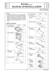
No.
Name
Shape
Q’ty
10. Screw A
(3 × 6 mm)
2
9646
11. Screw B
(3 × 8 mm)
2
9739
12. Screw C
(4 × 8 mm)
9
4511U012AA
I. Accessory parts
No.
Name
Shape
13. Screw D
(3 × 8 mm)
Q’ty
1
9735
14. Screw E
(4 × 8 mm)
1. Saddle unit
1
9J08IXC079DA
15. Shoulder
screw A
1
1
4511U013AA
16. Shoulder
screw B
4511IXC107DA
2. Creasing unit
2
4511U014AA
17. Installation
manual
1
1
set
4511IXC055DA
3. Exit tray
1
4980IXC019DA
4511U004AA
4. Shutter
1
After unpacking, be sure to get rid of the
packaging materials and keep them out of
the reach of children.
4511IXC024DA
5. Mounting
bracket (right)
Putting the head in the plastic bag
involves danger of suffocation.
1
4511U006AA
6. Mounting
bracket (left)
Note:
Take the same procedures, though the machine
illustrations or adjustment screens are different
from the ones in the procedures.
1
4511U007AA
7. Shutter
mounting
holder
2
II. When installing to the printers
4511U008AA
8. Creasing unit
adjusting plate
• This manual provides the illustration of the
machine used as MFP. However, the same installation procedure is used for the printers.
• For screen adjustment, make sure to use the field
service tools. Refer to the machine installation
manual regarding how to connect and use the
field service tools.
1
4511U009AA
9. Mounting
bracket cover
1
4511U011AA
E-1
4511-9560-01
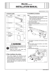
III. Installation procedures
3. If the finisher is mounted on the machine, remove
the finisher.
Note:
For the finisher removal procedure, see installation manual for finisher.
Note:
• When mounting the saddle stitcher, mount it
before mounting the finisher to the machine.
• When mounting the punch kit at the same time,
mount the punch kit first.
4. Remove the rear cover of the finisher (four
screws).
5. Disconnect the connector.
1. Turn off the machine and unplug the power cord
from the power outlet.
2. Remove the saddle unit and all other accessories
from the shipping carton and remove the protective tape and cushioning materials.
<Saddle unit>
4511IXC057DB
6. Remove the upper cover (three screws).
4511IXC108DA
<Creasing unit>
4511IXC058DB
7. Remove the cover (two screws).
4511IXC123DA
<Exit tray>
4512IXC040DB
8. If the punch unit is mounted to the finisher,
remove the punch unit.
Note:
For the punch unit removal procedure, see installation manual for punch kit.
4511IXC124DA
E-2
11. Let the connector of the creasing unit into the
hole shown in the illustration.
12. Carefully insert the creasing unit into the finisher
along the notch provided in the rear of the finisher.
Note:
Use care not to allow the parts shown in the illustration to hit against the mating portions while the
creasing unit is being inserted.
Insert it with the guide plate at the finisher side facing downward shown “OK” in the illustration.
9. Remove the guide plate (left) (two screws).
Note:
When mounting the punch kit at that time, it has
been removed.
Notch
4511IXC059DB
10. Mount the punch unit that has been removed in
step 8.
Note:
For the punch unit mounting procedures, see
installation manual for punch kit.
Parts
Hole
4511IXC060DB
Guide plate
Creasing unit
NG
OK
4511IXC082DB
E-3
13. Place the creasing unit adjusting plate beneath
the creasing unit and temporarily secure the unit
by tightening screw only temporarily (one screw
A furnished with saddle stitcher).
17. Connect the connector of the creasing unit.
4511IXC083DA
18. Reinstall the cover that has been removed in
step 7 (two screws).
* First, fit the tab in position.
4511IXC061DA
14. Secure the rear end of the creasing unit using
shoulder screw (one shoulder screw A furnished
with saddle stitcher).
Note:
No clearance is allowed between the shoulder
screw and the metal bracket.
15. Secure the creasing unit adjusting plate and
creasing unit using screw (one screw A furnished with saddle stitcher).
4512IXC054DA
19. Reinstall the upper cover that has been removed
in step 6 (three screws).
* First, fit the tab in position.
4511IXC063DB
4511IXC062DB
16. Securely tighten screw that has been tightened
only temporarily in step 13.
E-4
20. Reconnect the connector that has been disconnected in step 5.
21. Reinstall the rear cover that has been removed
in step 4 (four screws).
Note:
Be sure to reinstall the cover (1) that has been
removed in step 4.
25. Move the shutter up and down. Release the
shutter from a higher position to check to ensure
that the shutter falls by its own weight.
* If it does not fall by its own weight, move the
shutter up and loosen the screw of the shutter
mounting holder which can be seen from the
hole shown on the picture, and adjust the position of the shoulder screw B.
➀
4511IXC081DA
22. Mount the finisher to the machine.
Note:
For the finisher mounting procedures, see installation manual for finisher.
23. Install the shutter mounting holder to the tray
unit using screws (two screw B’s furnished with
saddle stitcher).
Hole
4511IXC111DA
26. Remove the finisher exit tray (two screws).
4511IXC109DA
24. Using shoulder screws, secure the shutter to the
shutter mounting holder (two shoulder screw B’s
furnished with saddle stitcher).
4511IXC112DA
27. Remove the exit tray mounting holders on the
right and left (one screw each).
4511IXC110DA
4511IXC113DA
E-5
31. Secure the mounting brackets in position following the order shown in the illustration (three
screw C’s each furnished with the saddle
stitcher).
28. Remove the right and left covers (two screws
each).
3
3
1
1
2
4511IXC114DA
2
29. Use a nipper, etc. to cut out two separation covers.
4511IXC071DA
32. Reinstall the right and left covers that has been
removed in step 28 (two screws each).
4510IXC029DA
30. Insert the left and right mounting brackets.
Note:
Make sure that the flat surface of each of the
mounting brackets faces inward when installed.
4511IXC116DA
33. Loosen the screw shown, move it to the front,
and then tighten it again (one screw).
Note:
• This step must be performed properly to prevent any trouble.
• Do not move the screw by using the adjust
plate.
• Be sure to move the screw itself.
4511IXC115DA
Adjust plate
4511IXC117DA
E-6
37. Reinstall the finisher exit tray that has been
removed in step 26 (two screws).
Note:
To prevent problems, be sure to securely tighten
the screws.
34. Reinstall the left exit tray mounting holder that
has been removed in step 27 (one screw).
Note:
Install the holder at a level one step lower than
where it was removed in step 27.
4511IXC085DA
4511IXC118DA
35. Use a nipper, etc. to cut out the crosshatched
portion of the right exit tray mounting holder that
has been removed in step 27.
38. Mount the saddle unit on the finisher.
Note:
Check that the tab of the saddle unit is below the
tab of the shutter.
4510IXC032DA
Tab of the shutter
36. Reinstall the right exit tray mounting holder (one
screw).
Note:
Install the holder at a level one step lower than
where it was removed in step 27.
Tab of the saddle unit
4511IXC119DA
4511IXC086DA
E-7
39. Secure the saddle unit to the mounting bracket
(left) (two screw C’s furnished with the saddle
stitcher).
Note:
Temporarily tighten the left screw, securely tighten
the right screw, and then securely tighten the left
screw.
43. Remove the connector cover from the finisher
(one screw).
44. Use a nipper, etc. to cut out the separation
cover.
Right
Left
4511IXC078DA
45. Connect the ground wire (one screw D furnished
with the saddle stitcher).
46. Connect the two connectors.
47. Insert the snap band.
4511IXC075DA
40. Open the saddle unit.
41. Secure the saddle unit to the mounting bracket
(right) (one screw C furnished with the saddle
stitcher).
Snap band
4511IXC079DB
48. Reinstall the connector cover that has been
removed in step 43 (one screw).
49. Install the exit tray.
4511IXC120DA
42. Install the mounting bracket cover to the mounting bracket (right) (one screw E furnished with
the saddle stitcher).
4511IXC052DA
4511IXC121DA
E-8
IV. Adjustments
* State the adjustments of A3
<Crease position adjustment>
1. Make a copy in the crease mode.
(Refer to the user’s guide (copy operations))
2. Fold the copy fed out along the crease.
3. Check the crease for deviation (measure width
A).
Reference: 0 ± 1.5 mm
here.
1. Plug the power cord into the power outlet and
turn on the machine.
<Crease tilt adjustment>
2. Load the drawer with A3
.
3. Select the crease mode and make a copy.
(Refer to the user’s guide (copy operations))
4. Fold the copy fed out along the crease.
5. Fold the copy fed out in half.
6. Check the crease for tilt (measure width A).
Reference: 0 ± 1.5 mm
A
A
Center
Exit direction
4511IXC090DA
Crease
4. Display the Service Mode screen.
(For details of how to display the Service Mode
screen, see the service manual.)
5. Touch “Finisher.”
Exit direction
4511IXC089DA
7. Open the front cover and loosen the screw on the
creasing unit adjusting plate.
8. Slide the adjusting plate to the right or left as necessary to adjust tilt.
* If the crease tilts as in step 6, move the adjusting
plate to the left as shown below.
A00JIXE118DA
6. Touch “CB-FN adjustment.”
4511IXC122DA
9. Make a copy and check the crease for tilt.
A0DHIXE004DA
E-9
7. Touch “Fold&Staple Pos. Adjustment.”
[If the crease deviates as shown below]
11. Using the
key, set the numeric value and
touch “END.”
A
4512IXE077DA
Exit direction
8. Touch “Fold Position Adjustment.”
4511IXC091DA
12.
13.
14.
15.
4511IXE104DA
9. Touch “A3
” and then touch “Normal Paper.”
4511IXE105DA
[If the crease deviates as shown below]
10.Using the
key, set the numeric value and
touch “END.”
A
Exit direction
4511IXC090DA
E-10
Touch “END.”
Touch “Exit” on the Service Mode screen.
Make a copy and check the crease for deviation.
Adjust the other sizes in the same way.
<Staple tilt adjustment>
1. Load a five-page A4
document in the document feeding tray.
2. Select the center staple mode and make a copy.
(Refer to the user’s guide (copy operations))
3. Fold the copy fed out along the crease.
4. Check the staple positions for tilt (measure width
A).
Reference: 0 ± 1.5 mm
A
<Staple position adjustment>
1. Load a five-page A4
document in the document feeding tray.
2. Select the center staple mode and make a copy.
(Refer to the user’s guide (copy operations))
3. Fold the copy fed out along the crease.
4. Check the staple position for deviation from the
crease (measure width A).
Reference: 0 ± 1.5 mm
A
Exit direction
Exit direction
4511IXC092DA
5. Open the saddle unit lock release lever.
6. Loosen the adjusting screw and move the saddle
to the left or right to adjust tilt as necessary.
* If the staple positions tilt as in step 4, move the
saddle to the left as shown below.
4511IXC093DA
5. Display the Service Mode screen.
(For details of how to display the Service Mode
screen, see the service manual.)
6. Touch “Finisher.”
A00JIXE118DA
4511IXC054DA
7. Touch “CB-FN adjustment.”
7. Make a copy and check the staple positions for
tilt.
A0DHIXE004DA
E-11
8. Touch “Fold&Staple Pos. Adjustment.”
[If the staple positions deviate as shown below]
12. Using the
key, set the numeric value and
touch “END.”
A
4512IXE077DA
Exit direction
9. Touch “Center Staple Position.”
4511IXC094DA
13. Touch “Enter” three times.
14. Touch “Exit” on the Service Mode screen.
15. Make a copy and check the staple position for
deviation from the crease.
16. Adjust the other sizes in the same way.
4511IXE104DA
10. Touch “A3
” and touch “Normal Paper.”
4511IXE106DA
[If the staple positions deviate as shown below]
11. Using the
key, set the numeric value and
touch “END.”
A
Exit direction
4511IXC093DA
E-12