1
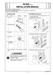
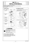
PK-515 Punch Kit
INSTALLATION MANUAL
Applied Machine: FS-519
I. Accessory parts
No.
Name
III. Installation procedures
Shape
1
Note:
• When mounting the punch kit, mount it before
mounting the finisher to the machine.
• When mounting the saddle stitcher at the same
time, mount the punch kit first.
1
1. Turn off the machine and unplug the power cord
from the power outlet.
2. Remove the protective tapes.
3. Remove the fixing brackets of the punch unit (four
screws).
Q’ty
1. Punch unit
4512IXC037DA
2. Punch box
4512U003AA
3. Label
1
4512IXC053DA
4. Screw
(3 × 6 mm)
2
9735
5. Installation
manual
1
set
4512IXC038DB
4. If the finisher is mounted on the machine, remove
the finisher.
Note:
For the finisher removal procedure, see installation manual for finisher.
4980IXC019DA
After unpacking, be sure to get rid of the
packaging materials and keep them out of
the reach of children.
5. Remove the rear cover of the finisher (four
screws).
6. Disconnect the connector.
Putting the head in the plastic bag
involves danger of suffocation.
II. When installing to the printers
• This manual provides the illustration of the
machine used as MFP. However, the same installation procedure is used for the printers.
• For screen adjustment, make sure to use the field
service tools. Refer to the machine installation
manual regarding how to connect and use the
field service tools.
4511IXC057DB
E-1
A0DH-9550-00
10. If the creasing unit is mounted to the finisher,
remove the creasing unit adjusting plate (one
shoulder screw, two screws).
7. Remove the upper cover (three screws).
4511IXC058DB
8. Remove the cover (two screws).
4512IXC040DB
4512IXC067DA
11. Insert the punch unit.
Note:
Take care so that the mylar will not be bent.
9. Remove the guide plate (right) (two screws).
Note:
When mounting the saddle stitcher at the same
time, remove the guide plate (left) (two screws).
12. Temporarily secure the punch unit (one screw
furnished with the punch kit).
Guide plate (right)
Mylar
4512IXC039DC
4512IXC046DA
Guide plate (left)
4511IXC059DB
E-2
13. Press the punch unit tightly up against the
machine frame.
14. Secure the punch unit to the finisher (one screw
furnished with the punch kit).
(2) Secure the rear end of the creasing unit using
shoulder screw (one shoulder screw that has
been removed in step 10).
Note:
No clearance is allowed between the shoulder
screw and the metal bracket.
(3) Secure the creasing unit adjusting plate and
creasing unit using screw (one screw that has
been removed in step 10).
4512IXC047DB
15. Securely tighten the screw that has been temporarily tightened in step 12 (one screw).
16. Mount the creasing unit adjusting plate that has
been removed in step 10.
When mounting the saddle stitcher at the same
time, mount the creasing unit at this point. (For
the saddle stitcher removal procedure, see
installation manual for saddle stitcher.)
(1) Place the creasing unit adjusting plate beneath
the creasing unit and temporarily secure the
unit by tightening screw only temporarily (one
screw that has been removed in step 10).
4512IXC069DA
(4) Securely tighten screw that has been tightened
only temporarily in step (1).
4512IXC068DA
E-3
17. Place the harness of the punch unit to the edge
cover and the hook of gear cover. Straighten the
code and mount the harness.
18. Connect the two connectors.
Hook
21. Reconnect the connector that has been disconnected in step 6.
22. Reinstall the rear cover that has been removed
in step 5 (four screws).
Note:
Be sure to reinstall the cover (1) that has been
removed in step 5.
Edge cover
➀
4512IXC048DB
19. Install the punch box.
4511IXC081DA
23. Mount the finisher to the machine.
Note:
For the finisher mounting procedures, see installation manual for finisher.
24. Affix the label to the front cover.
4512IXC049DB
20. Reinstall the upper cover that has been removed
in step 7 (three screws).
* First, fit the tab in position.
A0DHIXC005DA
4511IXC063DB
E-4
IV. Punch option setting
V. Punch hole deviance adjustment
1. Plug the power cord into the power outlet and
turn on the machine.
2. Display the Service Mode screen. (For details of
how to display the Service Mode screen, see the
service manual.)
3. Touch “Finisher.”
1. Make a copy in the punch mode.
(Refer to the user’s guide (copy operations))
2. Fold the copy into halves and check for possible
deviation in the punch hole positions.
Specifications: 0 ± 2.0 mm
4512IXC055DA
A00JIXE118DA
3. If holes are not aligned with each other, loosen
the adjusting screw (one screw).
4. Holding the upper part of the motor section, move
the punch unit to the front or rear as necessary.
Adjusting screw
4. Touch “Punch option setting.”
A0DHIXE004DA
5. Touch “PK-515” and select a desired number of
holes.
6. Touch “decision.”
4512IXC083DA
5. After the adjustment has been completed, tighten
the adjusting screw.
6. Make a copy and check the punch hole positions
again.
7. Use a nipper, etc. to cut out the separation cover
of the cover that has been removed in step 8 on
P. E-2.
A0DHIXE005DA
7. Touch “END.”
8. Touch “Exit” on the Service Mode screen.
4512IXC050DA
E-5
VI. Punch hole position adjustment
8. Reinstall the cover (two screws).
* First, fit the tab in position.
1. Make a copy in the punch mode.
(Refer to the user’s guide (copy operations))
2. Measure width A on the copy and check to see if
the measured dimension falls within the specified
range.
<North America: 2 holes, 3 holes>
Specifications: 9.5 ± 1.0 mm
<Europe: 4 holes>
Specifications: 11 ± 1.0 mm
<Sweden: 4 holes>
Specifications: 11.5 ± 1.0 mm
• If the measured width A outside the specified
range, perform the following procedure to punch
hole position adjustment.
4512IXC054DA
<North America:
2 holes>
A
<North America:
3 holes>
A
4512IXC056DA
<Europe: 4 holes>
A
4512IXE057DA
<Sweden: 4 holes>
A
4512IXE061DA
4512IXE062DA
3. Display the Service Mode screen.
(For details of how to display the Service Mode
screen, see the service manual.)
4. Touch “Finisher.”
A00JIXE118DA
E-6
VII. Punch regist loop size adjustment
5. Touch “CB-FN adjustment.”
1. Make a copy in the punch mode.
(Refer to the user’s guide (copy operations))
2. Check the tilt of the output paper.
• If it tilts, follow the procedures below for punch
loop adjustment.
3. Display the Service Mode screen.
(For details of how to display the Service Mode
screen, see the service manual.)
4. Touch “Finisher.”
A0DHIXE004DA
6. Touch “Punch Horizontal Position.”
A00JIXE118DA
5. Touch “CB-FN adjustment.”
4512IXE077DA
7. Set the correction value using the
/
keys.
• To make width A wider, enter a positive value.
• To make width A narrower, enter a negative
value.
A0DHIXE004DA
6. Touch “Punch Regist Loop Size.”
A0DHIXE006DA
8. Touch “END.”
9. Touch “Exit” on the Service Mode screen.
10. Make a copy and check the punch hole positions
again.
4512IXE077DA
E-7
7. Set the correction value using the
/
keys.
• To make loop length larger, enter a positive value.
• To make loop length smaller, enter a negative
value.
4512IXE079DA
8. Touch “END.”
9. Touch “Exit” on the Service Mode screen.
10. Make a copy again and check the deviance of
punch hole position.
E-8